Sonel PAT-806-IT User manual

USER MANUAL
PORTABLE APPLIANCE TESTER
PAT-806-IT
SONEL S.A.
Wokulskiego 11
58-100 Świdnica, Poland
Version 1.07 05.03.2020

PAT-806-IT –USER MANUAL
2
PAT-806-IT meter is a modern, high-quality meter, easy and safe in operation. Please acquaint your-
self with the present manual in order to avoid measuring errors and prevent possible problems relat-
ed to operation of the meter.

PAT-806-IT –USER MANUAL
3
CONTENTS
1Safety ................................................................................................................5
2General description and features of the instrument ....................................6
3Switching on and general settings ................................................................8
3.1 Power supply ...........................................................................................................8
3.2 Changing the type of mains (TN or IT).....................................................................8
3.3 Start test after switching the meter on...................................................................... 9
3.4 General Settings - MENU.......................................................................................10
3.4.1 Setting date and time......................................................................................................11
3.4.2 Communication with PC..................................................................................................12
3.4.3 Firmware update.............................................................................................................13
3.4.4 Setting the bar-code reader.............................................................................................13
3.4.5 Printer Settings ...............................................................................................................15
3.4.6 Transferring data to a pen-drive......................................................................................16
3.4.7 Setting nominal network voltage .....................................................................................17
3.4.8 Setting current values in the measurement of RPE on IEC lead test ................................18
3.4.9 Configuration of settings from PC ...................................................................................19
4Measurements................................................................................................22
4.1 Preliminary test ...................................................................................................... 22
4.2 Measurement of protective lead resistance using 200 mA current..............................24
4.3 Compensation of the test lead resistance during the measurement of the protective
lead resistance using 200 mA current (auto-zero).................................................27
4.4 Measurement of protective lead resistance using 10/25 A current........................28
4.4.1 Two-wire measurement of protective lead resistance using 10/25 A current...................29
4.4.2 Compensation of the test lead resistance during the measurement of the protective lead
resistance using 10 A or 25 A current (auto-zero) ...........................................................29
4.4.3 Three-wire measurement of protective lead resistance using 10/25 A current.................30
4.4.4 Four-wire measurement of protective lead resistance using 10/25 A current...................31
4.5 Measurement of insulation resistance.................................................................... 31
4.5.1 RISO measurement on devices of Class I.........................................................................32
4.5.2 RISO measurement on devices of Class II (III) .................................................................33
4.5.3 Three-point RISO measurement on welding equipment....................................................34
4.6 Measurement of substitute leakage current...........................................................36
4.7 Measurement of PE leakage current...................................................................... 39
4.8 Measurement of differential leakage current..........................................................40
4.9 Measurement of touch leakage current.................................................................. 42
4.10 Measurement of leakage current in the primary circuit of the welding machine using
PAT IPE adapter.................................................................................................... 43
4.11 Rated voltage measurement on welding equipment without load..........................46
4.12 Leakage current measurement on welding circuit IL.............................................. 48
4.13 Measurement of current, power consumption and voltage ....................................50
4.14 IEC lead test .......................................................................................................... 51
4.15 Automatic tests ......................................................................................................52
5Memory of measurement result data ...........................................................56
5.1 Storing the measurement results in the memory ...................................................56
5.2 Viewing memory data............................................................................................. 58
5.3 Deleting memory data............................................................................................ 58
5.3.1 Deleting bank data..........................................................................................................58

PAT-806-IT –USER MANUAL
4
5.3.2 Deleting the whole memory ............................................................................................ 59
6Report printing .............................................................................................. 60
7Data transmission ......................................................................................... 60
7.1 Computer connection accessories .........................................................................60
7.2 Data transmission with USB port............................................................................60
8Cleaning and maintenance........................................................................... 60
9Storage........................................................................................................... 60
10 Dismantling and Disposal ............................................................................ 61
11 Technical specifications............................................................................... 62
12 Accessories ................................................................................................... 69
12.1 Standard accessories.............................................................................................69
12.2 Optional accessories..............................................................................................69
13 Manufacturer.................................................................................................. 70
14 Laboratory services ...................................................................................... 71

PAT-806-IT –USER MANUAL
5
1 Safety
PAT-806-IT meter is designed for performing check tests on electrical equipment, providing
measurement results which determine the safety status of tested devices. Therefore, in order to pro-
vide conditions for correct operation and the correctness of the obtained results, the following rec-
ommendations must be observed:
Before you proceed to operate the meter, acquaint yourself thoroughly with the present manual
and observe the safety regulations and specifications determined by the producer.
Any application that differs from those specified in the present manual may result in a damage to
the device and constitute a source of danger for the user.
PAT-806-IT meter must be operated only by appropriately qualified personnel with relevant certif-
icates authorising the personnel to perform works on electric systems. Operating the meter by
unauthorised personnel may result in damage to the device and constitute a source of danger for
the user.
The instrument must not be used with installations or equipment situated in dangerous environ-
ments, e.g. where fire or explosion hazards exist.
It is unacceptable to operate the following:
A damaged meter which is completely or partially out of order,
A meter with damaged test leads insulation,
A meter stored for an excessive period of time in disadvantageous conditions (e.g. excessive
humidity). If the meter has been transferred from a cool to a warm environment with a high
level of relative humidity, do not start measurements until the meter is warmed up to the am-
bient temperature (approximately 30 minutes).
The meter may be supplied only from grounded mains sockets.
Before measurements may commence, make sure the test leads are connected to the appropri-
ate measurement sockets.
Do not touch the tested device during measurements.
Banana test sockets and the socket for testing IEC cables are protected against improper con-
nection to the voltage up to 300 V AC for 60 seconds.
Repairs may be carried out only by an authorised service point.
NOTE!
Only standard and additional accessories for a given device should be used, as listed
in the "Equipment" section. Use of different accessories can lead to errors in the test
connection and can introduce additional measurement uncertainties.
NOTE!
The plug on the housing near handle must be always tightened. It can be unscrewed
only when the device is transported by an aeroplane.
Note:
Due to continuous development of the meter’s software, the actual appearance of the
display, in case of some of the functions, may slightly differ from the display presented
in this operating manual.

PAT-806-IT –USER MANUAL
6
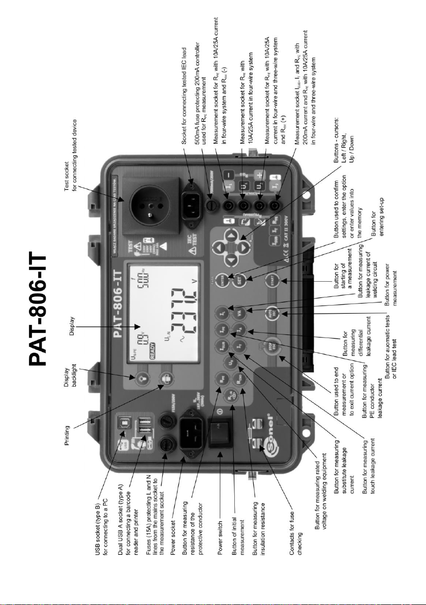
2 General description and features of the instrument
PAT-806-IT digital meter is intended to measure the basic parameters of portable electrical de-
vices (power tools, household appliances, etc.) important for their safety: protective conductor re-
sistance, insulation resistance, continuity of connections, the leakage current.
The meter may be used to test the equipment, in accordance with the following standards:
EN 60745-1 Hand-held motor-operated electric tools. Safety. Part 1: General requirements.
EN 61029 Safety of transportable motor operated electric tools. General requirements.
EN 60335-1 Household and similar electrical appliances. Safety. Part 1: General requirements.
EN 60950 Information technology equipment –Safety- Part 1: General requirements.
EN 60974-4 Arc welding equipment - Part 4: Periodic inspection and testing
VDE 0404-1 Prüf- und Messeinrichtungen zum Prüfen der elektrischen Sicherheit von elektri-
schen Geräten. Teil 1: Allgemeine Anforderungen.
VDE 0404-2 Prüf- und Messeinrichtungen zum Prüfen der elektrischen Sicherheit von elektri-
schen Geräten. Teil 2: Prüfeinrichtungen für Prüfungen nach Instandsetzung, Änderung oder für
Wiederholungsprüfungen.
VDE 0701-0702 Prüfung nach Instandsetzung, Änderung elektrischer Geräte. Wiederho-
lungsprüfung elektrischer Geräte. Allgemeine Anforderungen für die elektrische Sicherheit.
Basic functions of the instrument:
Measurement of network voltage and frequency
Rated voltage measurement on welding equipment
Checking the resistance of L-N circuit
Checking the fuse
Measurement of protective conductor resistance (Protection class - I):
technical measurement method
measurement with sinusoidal current of network frequency and values: 200 mA, 10 A and
25 A
adjustable measurement time
adjustable upper limit in the range of: 10 mΩ …1.99 Ω with resolution 0.01 Ω
Measurement of insulation resistance:
three test voltages: 100 V, 250 V and 500 V
measurement of insulation resistance up to 600 M
automatic discharge of the capacitance of tested object after the insulation resistance meas-
urement is completed
adjustable measurement time
adjustable lower limit within the range of 0.1 MΩ ….9.9 MΩ with resolution of 0.1 MΩ
three point measurement of insulation resistance on welding equipment
Measurement of substitute leakage current:
adjustable measurement time
adjustable upper limit in the range of: 0.01 mA ... 9.9 mA with resolution of 0.01 mA/0.1 mA
Measurement of PE leakage current
adjustable measurement time
adjustable upper limit in the range of: 0.01 mA ... 9.9 mA with resolution of 0.01 mA/0.1 mA

PAT-806-IT –USER MANUAL
7
Measurement of differential leakage current:
adjustable measurement time
adjustable upper limit in the range of: 0.01 mA ... 9.9 mA with resolution of 0.01 mA/0.1 mA
Measurement of touch leakage current:
adjustable measurement time
adjustable upper limit in the range of: 0.01 mA ... 1.99 mA with resolution of 0.01 mA
Leakage current measurement on welding circuit:
adjustable measurement time
adjustable upper limit in the range of: 0,1 mA…14,9 mA with resolution 0,1 mA
Power measurement:
adjustable measurement time
Current consumption measurement
IEC lead test
Other:
automatic selection of measuring range
990 memory cells for storing individual measurement results with the option to transfer them
to a PC via USB socket or printing
cooperation with the bar-code reader and printer
large, readable display with backlight option
ergonomic operation
Note:
The displayed E02 symbol informs that the 10/25 A test set is damaged. The machine
must be sent for repair.

PAT-806-IT –USER MANUAL
8
3 Switching on and general settings
3.1 Power supply
The device is powered from the network 187 V ... 265 V, 50 Hz.
Two 15 A fuses protect L and N lines from the supply socket to the test socket, they are tripped
when current consumption from the test socket is too high (>16 A).
500 mA fuse protects 200 mA current controller for RPE measurement.
3.2 Changing the type of mains (TN or IT)
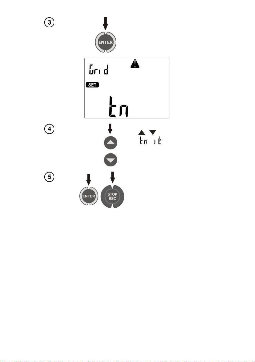
Connect the device to the target mains.
Turn on the device and keep SET
button pressed, until the following
screen is displayed:
PAT-806-IT –USER MANUAL
9
Press ENTER.
Use , buttons to set mains
type ( or ).
Press ENTER to confirm your
choice, press ESC to exit to the
main menu.
3.3 Start test after switching the meter on
After switching on, the meter performs self-test to check its correct operational condition and
when this test is successfully completed, the meter automatically performs the following measure-
ments:
measurement of the voltage in the power supply socket, i.e. the voltage between L and N of
power supply to the meter
measurement of mains frequency
checking the continuity PE in the power supply socket
measuring the voltage between N and PE in the power supply socket
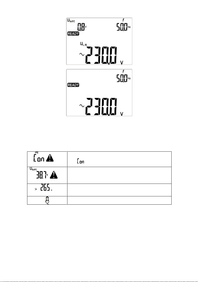
When everything is correct the following screen is displayed:
PAT-806-IT –USER MANUAL
10
- for TN mains
- for IT mains
Notes:
- When the network voltage is below 187 V the meter turns off automatically.
Additional information displayed by the meter
, and
an acoustic signal
Lack of PE continuity, the measurements are blocked (mes-
sage blinks).
, and
an acoustic signal
Voltage UN-PE > 25 V, the measurements are blocked (the
voltage value blinks), ), for IT mains, the measurements are
blocked for voltage L-PE >180V.
and
an acoustic signal
Mains voltage > 265 V, measurements are blocked.
Exchanged L and N, measurements are possible.
3.4 General Settings - MENU
By pressing SET button the user enters the mode where the following actions are available:
setting date and time
communicating with PC
updating firmware
operating the meter with a bar-code reader and printer
transferring data to a pen-drive
setting nominal network voltage
setting current values in the measurement of RPE on IEC lead.

PAT-806-IT –USER MANUAL
11
To enter the setting mode (MENU):
press SET button
Press ENTER to enter the parameter
setting.
Use buttons , to go to the
next parameter.
Use , to set the parameter
value.
Press ENTER to approve the set-
ting, press ESC go to the main
MENU without changing any set-
tings.
Notes:
- The value or symbol to be changed is blinking.
- Exit MENU using STOP/ESC.
- Settings are stored in memory after switching off the meter.
3.4.1 Setting date and time

PAT-806-IT –USER MANUAL
12
Press ENTER.
Use , to move
to the next group of
digits, using ,
set desired val-
ue.
Press ENTER to confirm the set-
tings or ESC, to exit to main MENU
without changing any settings.
3.4.2 Communication with PC
Press ENTER to start the transmis-
sion.

PAT-806-IT –USER MANUAL
13
3.4.3 Firmware update
Press ENTER to start the transmis-
sion. On PC run the program down-
loaded from www.sonel.pl.
Notes:
- New versions of software for the meter are available at www.sonel.pl.
- This function may be used only by the computer proficient users.
- During programming, do not turn off the power supply of the meter and the power supply should be
stable. Do not disconnect the USB cable.
3.4.4 Setting the bar-code reader
Press ENTER.

PAT-806-IT –USER MANUAL
14
Use , to set
the operation of the
meter with the bar-
code reader ( ) or
without it ( ).
Press ENTER, to confirm the set-
tings, or ESC, to exit to main MENU
without changing any settings.
Notes:
- The reader and printer have been programmed to read the codes in CODE128 standard (in PAT de-
vices we use digits only). PAT accepts only 7-character codes (e.g. "1234567"), any other are con-
sidered invalid. Therefore, if you attempt to read a 6-character code (or shorter) the reader will read it,
but PAT will not save it - the same applies to 8-character codes and longer.
- The bar-code contains only ID number of the device, no additional information is coded.
- Reader configuration:
1. Connect the reader to your PC.
2. Wait until the reader is installed on your system.
3. Point the reader at the following code pressing the button. The reader signals successful read-out
by lighting green LED and a beep.

PAT-806-IT –USER MANUAL
15
3.4.5 Printer Settings
Press ENTER.
Use , to set
the operation of the
meter with the printer
( ) or without it
( ).
Press ENTER, to confirm the set-
tings, or ESC, to exit to main MENU
without changing any settings.
Note:
- The printer must be connected to any of the USB socket of "Host" type.
- Supported types of printers: Brother PT-9700PC, Brother QL-720NW, Brother QL-820NWB.
PAT-806-IT –USER MANUAL
16
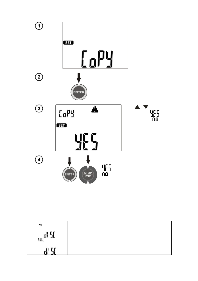
3.4.6 Transferring data to a pen-drive
Press ENTER.
Use , to set
copying data ( )
or its absence ( ).
Press ENTER, to confirm the set-
tings and start data copying for
, or to exit to main MENU for
, or ESC, to exit to main MENU
without changing any settings.
Notes:
- Pen-drive must have FAT32 file system.
- Pen-drive must be plugged into the left USB socket of "Host" type.
- The content of memory is transferred to the pen-drive as a file in an independent format interpreted
by "Sonel Reader" freeware and "Sonel PAT" commercial software.
Additional information displayed by the meter
No communication or poor communication with the pen-
drive.
Pen-drive memory is full.

PAT-806-IT –USER MANUAL
17
3.4.7 Setting nominal network voltage
Press ENTER.
Use , to set
the desired volt-
age.
Press ENTER, to confirm the set-
tings, or ESC, to exit to main MENU
without changing any settings.
Notes:
- Nominal network voltage is used in ISUB function for calculating the leakage current, which is meas-
ured at a voltage of 40V and its value is rescaled to the nominal voltage.

PAT-806-IT –USER MANUAL
18
3.4.8 Setting current values in the measurement of RPE on IEC lead test
Press ENTER.
Use , to set
the test current (10 A
or 200 mA).
Press ENTER, to confirm the set-
tings, or ESC, to exit to main MENU
without changing any settings.
Table of contents
Other Sonel Test Equipment manuals


Sonel
Sonel LKZ-1000 User manual

Sonel
Sonel PAT-10 User manual

Sonel
Sonel PAT-800 User manual

Sonel
Sonel S-36 VLF User manual

Sonel
Sonel PAT-80 User manual

Sonel
Sonel P-4 User manual

Sonel
Sonel P-3 User manual

Sonel
Sonel MRP-201 User manual

Sonel
Sonel TKF-13 Installation manual

Sonel
Sonel MIC-10s1 User manual


