Sonel PAT-80 User manual

1

2

USER MANUAL
PORTABLE
APPLIANCE TESTERS
PAT-80 ●PAT-85 ●PAT-86
SONEL S.A.
Wokulskiego 11
58-100 Świdnica
Version 1.0430.07.2020

PAT-80 ●PAT-85 ●PAT-86 –USER MANUAL
2
PAT-80/85/86 tester is a modern, high-quality tester, easy and safe in operation. Please acquaint
yourself with the manual in order to avoid measuring errors and prevent possible problems related to
operation of the tester.

PAT-80 ●PAT-85 ●PAT-86 –USER MANUAL
3
CONTENTS
1Safety ................................................................................................................5
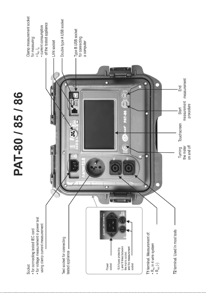
2General description and features of the instrument ....................................6
3Switching on and main menu.........................................................................8
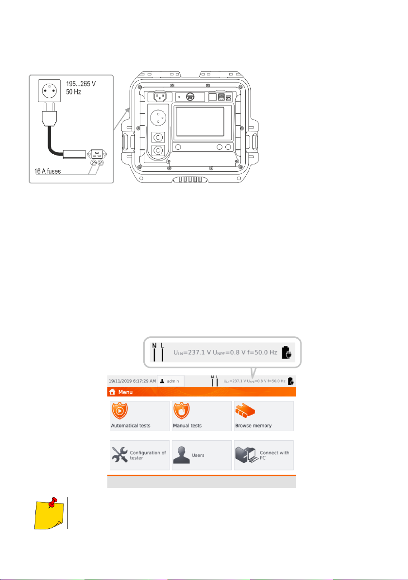
3.1 Power supply ...........................................................................................................8
3.2 Start test after switching the tester on......................................................................8
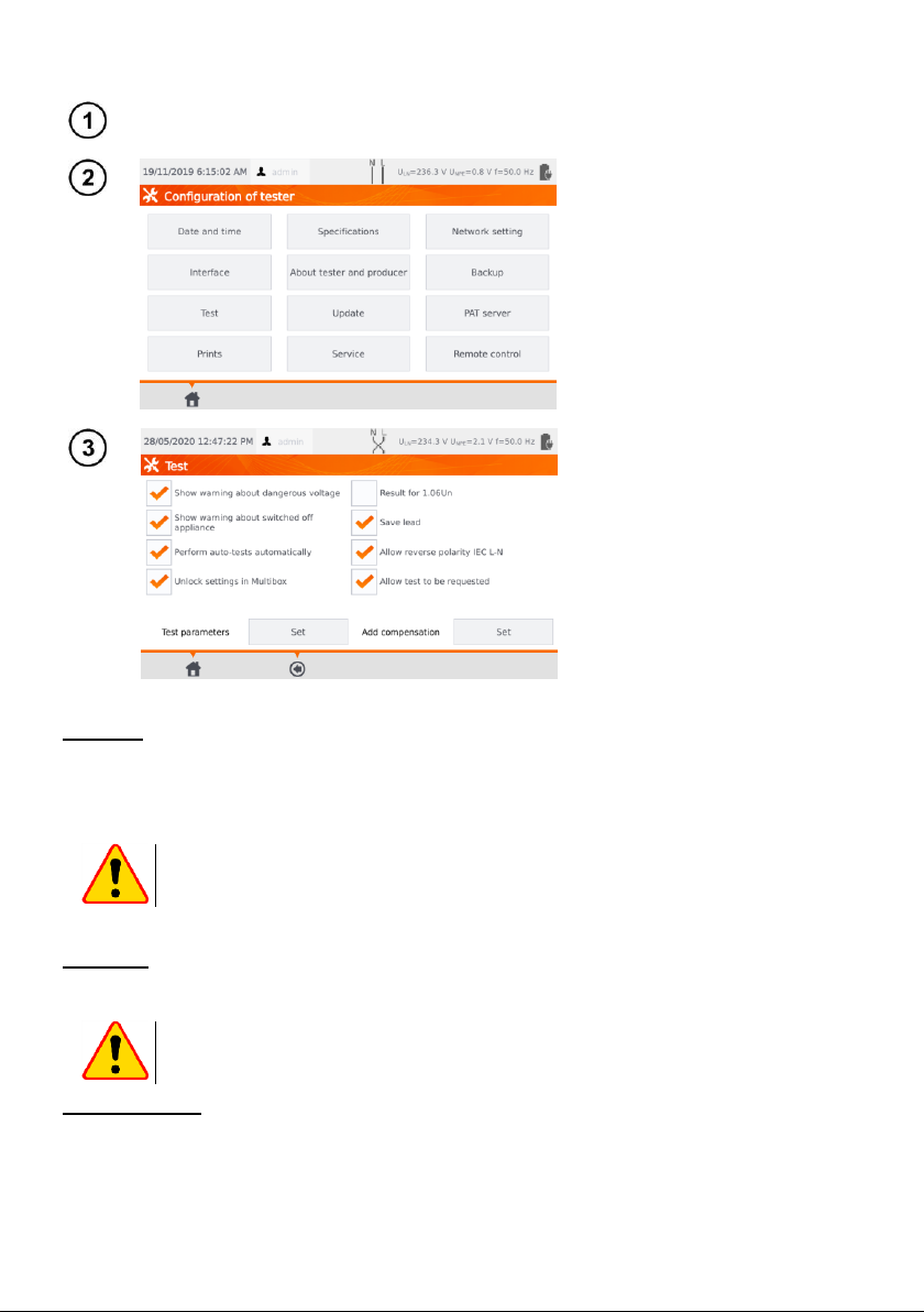
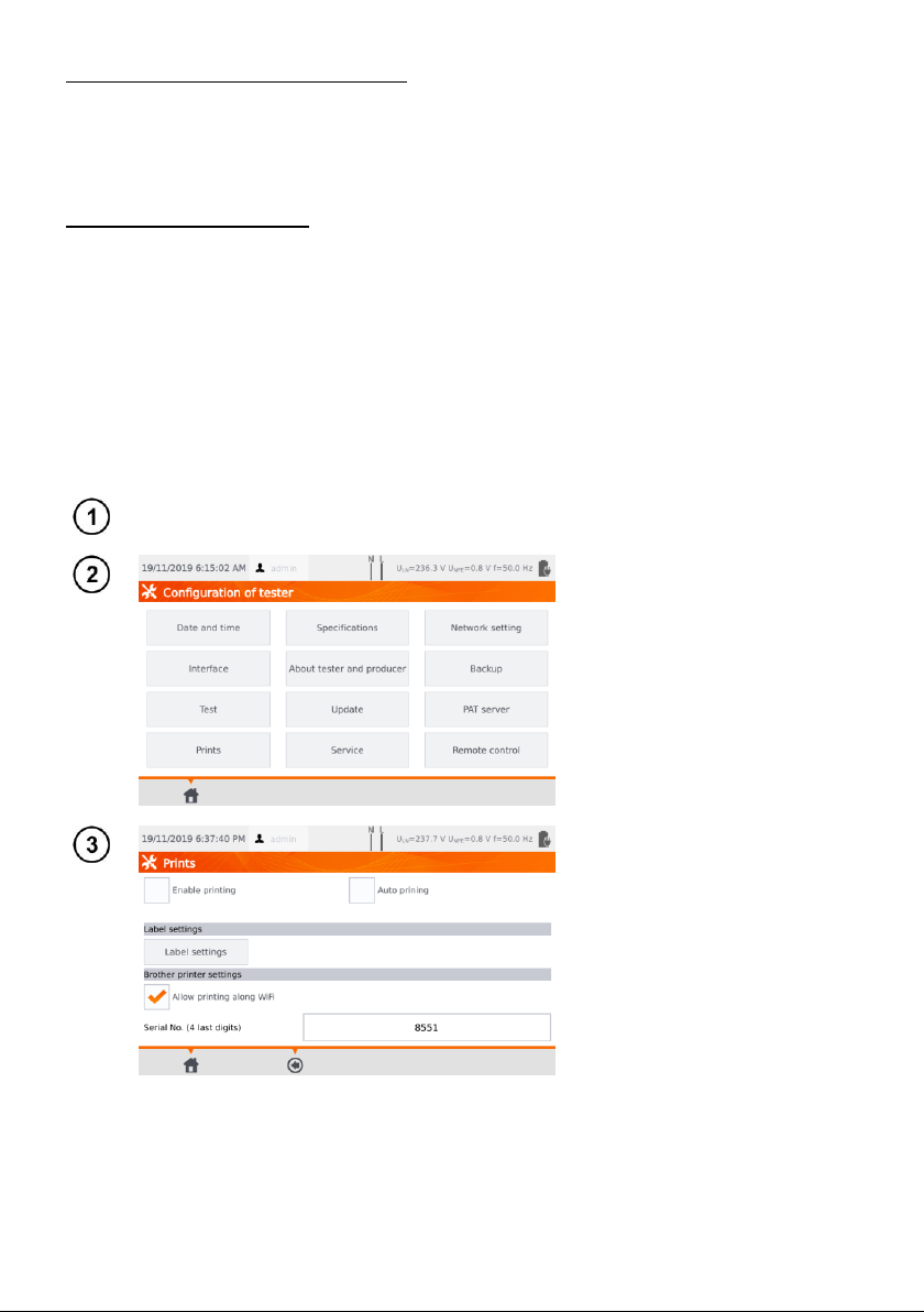
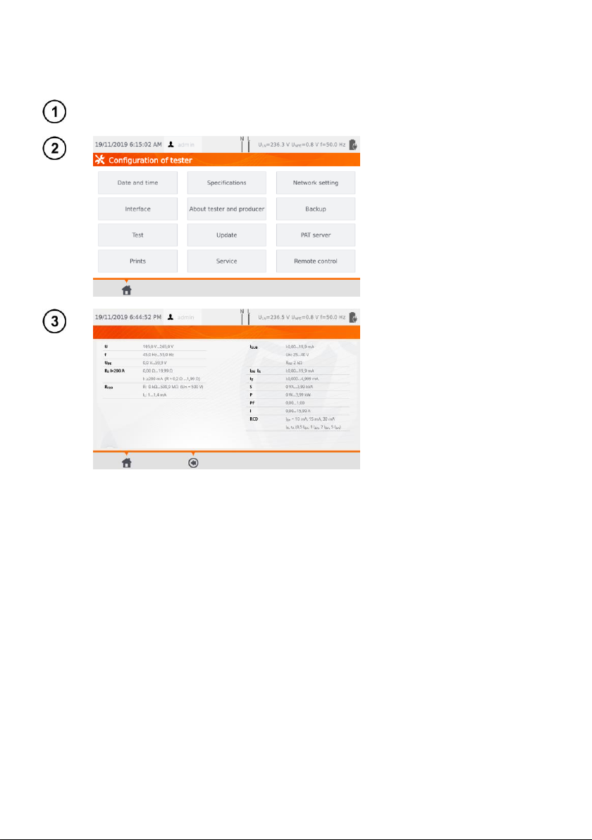
3.3 General settings –menu..........................................................................................9
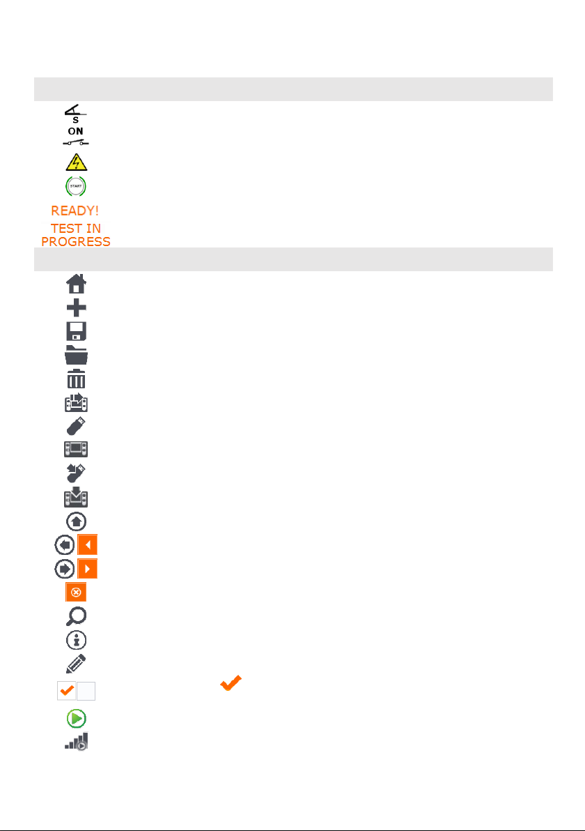
3.3.1 Symbols on screen .........................................................................................................10
3.3.2 Setting date and time......................................................................................................11
3.3.3 Interface settings. QR-code scanner initialization............................................................12
3.3.4 Measurement settings.....................................................................................................13
3.3.5 Printing ...........................................................................................................................14
3.3.6 Specifications..................................................................................................................16
3.3.7 Information about tester and producer.............................................................................17
3.3.8 Firmware update.............................................................................................................17
3.3.9 Service............................................................................................................................18
3.3.10 WiFi settings...................................................................................................................19
3.3.11 Bluetooth settings ...........................................................................................................21
3.3.12 Backup............................................................................................................................21
3.3.13 PAT Server (optional function)........................................................................................22
3.3.14 Remote control (optional function)...................................................................................23
3.3.15 List of Users....................................................................................................................24
a.Managing Users................................................................................................................... 24
b.Switching Users ................................................................................................................... 25
3.3.16 Memory structure (clients, objects, subobjects and appliances)......................................26
a.Adding clients....................................................................................................................... 26
b.Adding objects...................................................................................................................... 28
c.Adding appliances................................................................................................................ 30
d.Deleting clients, objects and appliances............................................................................... 31
3.3.17 Communication with PC..................................................................................................32
4Measurements................................................................................................33
4.1 Visual check (preliminary test)............................................................................... 33
4.2 Measurement of protective conductor resistance RPE............................................ 34
4.3 Measurement of insulation resistance RISO............................................................ 38
4.4 Measurement od substitute leakage current ISUB ................................................... 41
4.5 Measurement of leakage current IPE ...................................................................... 43
4.6 Measurement of differential leakage current IΔ...................................................... 46
4.7 Measurement of touch leakage current IT..............................................................49
4.8 Measurement of current with clamp....................................................................... 51
4.9 IEC cord test ..........................................................................................................52
4.10 Testing PRCD devices (with built-in RCD).............................................................53
4.11 Measurement of fixed RCD parameters.................................................................54
4.12 SELV/PELV appliances test................................................................................... 56
4.13 Power test.............................................................................................................. 57
5Measurement of welding machines..................................................59
5.1 Measurement of RISO (LN-S, PE-S) in welding machines ...................................... 59
5.2 Measurement of leakage current IPin welding machines ...................................... 61

PAT-80 ●PAT-85 ●PAT-86 –USER MANUAL
4
5.3 Measurement of welding circuit leakage current IL.................................................64
5.4 Welding machine voltage without load U0..............................................................65
6Automatical tests .......................................................................................... 67
6.1Configuring automatical tests.................................................................................67
6.2 Automatical tests....................................................................................................68
6.3 Multibox function.....................................................................................................70
6.3.1 Multibox OFF.................................................................................................................. 70
6.3.2 Multibox ON ................................................................................................................... 71
7Memory of measurement results................................................................. 72
7.1 Storing the measurement results in the memory....................................................72
7.2 Browsing memory data...........................................................................................73
7.3 ‘Search’ option in the memory................................................................................75
7.4 Moving appliance into another object.....................................................................76
7.5 Copying client’s data from memory into USB drive back and forth.........................77
7.6 Deleting memory data ............................................................................................78
7.7 Meter’s data backup ...............................................................................................79
8Label printing................................................................................................. 80
8.1 Printing availability..................................................................................................80
8.2 Label types.............................................................................................................81
9Power supply................................................................................................. 81
10 Cleaning and maintenance........................................................................... 81
11 Storage........................................................................................................... 82
12 Dismantling and Disposal ............................................................................ 82
13 Technical data................................................................................................ 82
13.1 Measurement of network parameters.....................................................................82
13.2 Measurement of PE resistance ..............................................................................83
13.3 Measurement of insulation resistance....................................................................84
13.4 Measurement of leakage current............................................................................86
13.5 Testing RCDs / PRCDs ..........................................................................................88
13.6 Power test...............................................................................................................89
13.7 Measurement of welding machine voltage without load ............................90
13.8 Other technical data ...............................................................................................91
14 Accessories ................................................................................................... 92
14.1 Standard accessories.............................................................................................92
14.2 Optional accessories..............................................................................................92
15 Manufacturer.................................................................................................. 93
16 Laboratory services ...................................................................................... 94

PAT-80 ●PAT-85 ●PAT-86 –USER MANUAL
5
The icon with the meter name is placed next to sections of the text that refer to specific fea-
tures of the device. All other parts of the text relate to all types of the device.
1 Safety
PAT-80/85/86 testers are designed for performing check tests, providing results which determine
the safety status of electrical equipment. Therefore, in order to provide conditions for correct opera-
tion and the correctness of the obtained results, the following recommendations must be applied:
Before you commence operating the tester, acquaint yourself thoroughly with the present manual
and observe the safety regulations and specifications determined by the manufacturer.
Any application that differs from those specified in this manual may result in a damage to the de-
vice and constitute a source of danger for the user.
PAT-80/85/86 tester must be operated only by appropriately qualified personnel. Operating the
tester by unauthorised personnel may result in damage to the device and constitute a source of
danger for the user.
Using this manual does not exclude the need to comply with occupational health and safety regu-
lations and with other relevant fire regulations required during the performance of a particular type
of work. Before starting the work with the device in special environments, e.g. potentially fire-
risk/explosive environment, it is necessary to consult it with the person responsible for health and
safety.
It is forbidden to operate the following:
A damaged tester which is completely or partially out of order,
A tester with damaged test leads insulation,
A tester stored for an excessive period of time in disadvantageous conditions (e.g. excessive
humidity). If the tester has been transferred from a cool to a warm environment with a high
level of relative humidity, do not start measurements until the tester is warmed up to the am-
bient temperature (approximately 30 minutes).
The tester may be powered only from grounded mains sockets.
Before starting any measurement, make sure the test leads are connected to the proper test
sockets.
Do not touch the tested device during measurements.
Test sockets and the socket for testing IEC cords are protected against improper connection to
the voltage up to 300 V AC for 60 seconds.
Repairs may be carried out only by an authorised service point.
NOTE!
Only standard and additional accessories for a given device should be used, as listed
in section 14. Use of different accessories can lead to errors in the test connection
and can introduce additional measurement uncertainties.
Due to continuous development of the tester’s software, the actual appearance of
the display, in case of some of the functions, may slightly differ from the display
presented in this operating manual.
An attempt to install drivers in 64-bit Windows 8 may result in displaying "Installation
failed" message.
o Cause: Windows 8 by default blocks drivers without a digital signature.
o Solution: Disable the driver signature enforcement in Windows.

PAT-80 ●PAT-85 ●PAT-86 –USER MANUAL
6
2 General description and features of the instrument
PAT-80/85/86 digital tester is intended to measure the basic parameters of portable electrical ap-
pliances (power tools, household appliances, etc.) important for their safety: protective conductor re-
sistance, insulation resistance, continuity of connections, leakage current and RCDs.
The tester may be used to test equipment in accordance with the following standards:
EN 60745-1 Hand-held motor-operated electric tools. Safety. Part 1: General requirements.
EN 61029 Safety of transportable motor operated electric tools. General requirements.
EN 60335-1 Household and similar electrical appliances. Safety. Part 1: General requirements.
EN 60950 Information technology equipment –Safety- Part 1: General requirements.
EN 61557-6 Electrical safety in low voltage distribution systems up to 1000 V AC and 1500 V DC
- Equipment for testing, measuring or monitoring of protective measures - Part 6: Effectiveness of
residual current devices (RCD) in TT, TN and IT systems.
VDE 0404-1 Testing and Measuring Equipment for Checking the Electric Safety of Electric De-
vices - Part 1: General Requirements.
VDE 0404-2 Testing and Measuring Equipment for Checking the Electric Safety of Electric De-
vices - Part 2: Testing Equipment for Tests after Repair, Change or in Case of Repeat Tests.
VDE 0701-0702 Inspection after Repair, Modification of Electrical Appliances.
Repeat Testing of Electrical Equipment. General Requirements for Electrical Safety.
AS/NZS 3760:2010 In-service safety inspection and testing of electrical equipment.
Basic functions of the instrument
Measurement of network voltage and frequency
Measurement of protective conductor resistance (protection class - I)
technical measurement method
measurement with sinusoidal current of network frequency and following currents:
200 mA
10 and 25 A
adjustable measurement time
adjustable upper limit in the range of: 10 mΩ…1.99 Ω with 0.01 Ωresolution
Measurement of insulation resistance
Four test voltages:
100 V
250 V, 500 V
1000 V
measurement of insulation resistance up to 599 M
automatic discharge of the capacitance of tested object after the insulation resistance meas-
urement is completed
adjustable measurement time
adjustable lower limit within the range of 0.1 MΩ….9.9 MΩ with 0.1 MΩ resolution
Measurement of substitute leakage current
adjustable measurement time
adjustable upper limit in the range of: 0.01 mA ... 9.9 mA with 0.01 mA / 0.1 mA resolution
Measurement of PE leakage current
adjustable measurement time
adjustable upper limit in the range of: 0.01 mA ... 9.9 mA with 0.01 mA / 0.1 mA resolution
measurement of the current with clamp

PAT-80 ●PAT-85 ●PAT-86 –USER MANUAL
7
Measurement of differential leakage current
adjustable measurement time
adjustable upper limit in the range of: 0.01 mA ... 9.9 mA with 0.01 mA / 0.1 mA resolution
measurement of the current with clamp
Measurement of touch leakage current
adjustable measurement time
adjustable upper limit in the range of: 0.01 mA ... 1.99 mA with 0.01 mA / 0.1 mA resolution
Measurement of welding machine parameters
primary circuit leakage current IP
welding circuit leakage current IL
URMS voltage
UPvoltage (DC and ACpeak)
Measurement of power P, Q and S
adjustable measurement time
measurement of power factor PF
measurement of cosφ
measurement of THD of voltage and current
Measurement of current consumption
Measurement with the device's internal measurement circuits or with clamp
Measurement of RCD / PRCD parameters
time-delayed and general
IΔn= 10 mA, 15 mA, 30 mA
measurement of IAcurrent and RCD tripping time tAfor 0.5 IΔn, 1 IΔn, 2 IΔn, 5 IΔn
Visual test
IEC cord test
Furthermore:
automatic selection of measuring range
tree structure of measurement results memory with provision of printing or transferring the re-
sults to PC via USB link
configurable with a QR-code scanner and printer
power supply sustained for ca. 1 hour after disconnecting mains power supply with the use of
built-in battery
ergonomic operation

PAT-80 ●PAT-85 ●PAT-86 –USER MANUAL
8
3 Switching on and main menu
3.1 Power supply
The device is powered from
mains 195…265 V, 50 Hz.
Two 16 A fuses protect L and N
lines from the supply socket to the
test socket. They are tripped when
current consumption from the test
socket is too high (>16 A).
3.2 Start test after switching the tester on
After switching on, the tester performs a self-test to check its correct operational condition. When
this test is successfully completed, the tester automatically performs the following measurements:
voltage between L and N of power supply,
measurement of mains frequency,
checking the continuity PE in the power supply socket,
measuring the voltage between N and PE in the power supply socket,
indicates swapped L and N terminals
Upon completing above mentioned measurements, main menu screen is displayed. On the right up-
per corner of the screen mains network monitor is presented. It shows polarity of the power supply,
voltage between N and PE, voltage between L and N, as well as mains frequency.
For mains voltages below 195 V and above 256 V all test functions are automatically
blocked.

PAT-80 ●PAT-85 ●PAT-86 –USER MANUAL
9
Additional information displayed on the screen
Voltage on the meter!
Voltage UN-PE > 25 V or lack of PE continuity, measurements are
blocked.
Message
Too high U L-N!
and audible signal
Mains voltage > 265 V, measurements are blocked.
Correct polarity of power supply (L and N), measurements possible.
Incorrect polarity of power supply, swapped L and N in the power
supply socket of the tester. The meter automatically swaps L and N
in the test socket –measurements are possible.
Error message indicating incorrect voltage frequency may be caused by supplying
power from an unstable voltage source (e.g. generator).
3.3 General settings –menu
In the menu the following actions are available:
automatical tests,
manual tests,
memory browsing,
configuration of tester:
date and time: setting date and time,
interface: switching on/off audible signals, choosing language,
measurements: setting nominal mains voltage and additional options,
prints: printing settings,
specifications,
info about tester and producer,
update: firmware upgrade,
service (service mode),
network setting: WiFi configuration,
list of users,
connection with PC.
Settings are saved and remembered after switching off the tester.
Automatical tests, Manual tests and Browsing memory are described in other
chapters of this manual.

PAT-80 ●PAT-85 ●PAT-86 –USER MANUAL
10
3.3.1 Symbols on screen
Measurements
connect measurement probe to the object
appliance under test must be switched on
WARNING: mains voltage in the measurement socket of the tester during the
measurement, appliance under test will switch on and go
press START to start the test
the tester is ready to commence the test
test procedure is in progress
Interface
go back to the main menu
add new element (client, site, appliance) / another measurement in Multibox function
save data (select appliance when saving to memory)
opening object or appliance data
deleting object or appliance
moving appliance into other object
go to USB flash drive memory (visible only if a USB flash drive is inserted)
go to meter memory (visible only if a USB flash drive is inserted)
save to USB flash drive memory (visible only if a USB flash drive is inserted)
save records from USB memory to the meter
move one level up
previous screen / window
next screen / window
close the window without saving changes
searching (e.g. client, object, appliance)
help
editing data of the selected element (e.g. client, site, appliance)
checkbox. Symbol inside the square means that the selected option is on or
given content assigned to this field has been confirmed and is correct
commencing the measurement
connection with selected WiFi network (see sec. 3.3.10)

PAT-80 ●PAT-85 ●PAT-86 –USER MANUAL
11
3.3.2 Setting date and time
Press Configuration of tester.
Press Date and time.
Press the field you intend to
change.
In the date edit window type in
proper value. Press to pro-
ceed to editing next parameter.
Enter saves changes and clos-
es the window.
After entering new values press
Set to confirm the date and
time settings.

PAT-80 ●PAT-85 ●PAT-86 –USER MANUAL
12
3.3.3 Interface settings. QR-code scanner initialization
Press Configuration of tester.
Press Interface
By checking the box Auto In-
crement Appliance/Device ID,
you will enable or disable the
automatic transmission of the
next registration number as-
signed to the next device being
added.
The Sound messages field
enables or disables the sound
signals.
The Language field allows you
to select a language.
To initialize the QR code scan-
ner on the meter, connect the
scanner and scan the displayed
code with it.

PAT-80 ●PAT-85 ●PAT-86 –USER MANUAL
13
3.3.4 Measurement settings
Press Configuration of tester.
Select Test.
Tick checkboxes corresponding
to the desired options.
Then set test parameters:
type, frequency and volt-
age of the mains that the
meter is powered from,
measurement delay.
Warnings
Show warning about dangerous voltage –switch on/off warnings about the possibility of the volt-
age being dangerous to user that may appear during tests.
Show warning about switched off appliance –switch on/off notification that the tested appliance is
not connected or it's not turned on.
NOTE!
It is advised for less experienced users to keep all the above warnings on.
Auto-tests
Perform auto-tests automatically –switch on/off automatic mode of performing autotests, which is
performing the complete set of autotests after single press of START button.
NOTE!
It is advised for less experienced users to keep all the above warnings on.
Polarity IEC L-N:
Allow reverse polarity IEC L-N –allows interchanging of L and N lines in the tested IEC cord. The
test result is displayed as positive.

PAT-80 ●PAT-85 ●PAT-86 –USER MANUAL
14
Substitute leakage current measurement
Mains nominal voltage –is used to calculate the ISUB equivalent leakage current according to the
formula: ISUB = (IMEASURED x Un)/UMEASURED
Result for 1.06Un –the result of ISUB measurement is multiplied by 1.06, which is required by some
standards.
Power cord for the appliance
Save lead –after ticking this box, the power cord is saved in the memory and printed on a printout as
a separate appliance. Otherwise it is considered as an integral part of the appliance.
Unlock settings in Multibox –if Multibox is switched on, the option enables changing the measure-
ment settings during the autoprocedure realization, however this change is possible only after the first
measurement of a given quantity.
Add compensation –compensation of test leads resistance. Various values in depending on the
measuring current (200 mA, 10 A, 25 A).
Delay –the delay between powering the tested object and starting a measurement.
3.3.5 Printing
Press Configuration of tester.
Press Prints.
In the main window you can
manage communication with
printers.
Enable printing - enables /
disables printer support.
Auto printing - automatic print-
ing after the test.
If you want to connect to your
Brother D3 printer via WiFi, you
must enter the last 4 digits of its
serial number in the Serial No.
field.
Select Label settings to decide
what to print on the labels.

PAT-80 ●PAT-85 ●PAT-86 –USER MANUAL
15
Select desired options by ticking
empty squares.
QR code type
Normal –stores all information about the tested device: ID, name, measurement procedure number,
technical data, location in memory, etc.
Shortened –stores only the ID of the tested device and its location in the meter memory.
Logo
Placing logo on the print-out. Logo can be changed by using Sonel Reader software.
Preferred format
Detailed –contains a list of questions of the visual examination together with the assessment and
the results of individual measurements with the assessment.
Standard –includes overall result of the test, logos and additional data (name of the device, measur-
ing person).
Shorted –similar to standard format but without the logo and additional information.
Mini –only the identifier, name and QR code of the tested device are printed.
Templates for automatic printout
Appliance label –label with a test result of an appliance.
Appliance + IEC label –label with a test result of an appliance and IEC power cord.
RCD label –label with an RCD test result.
Print line with retest [months]
Printing stripe on the left, right, or both sides of the label, depending on the number of the months, af-
ter which retest of the appliance must be done. The number of months is selected by clicking on
proper field.

PAT-80 ●PAT-85 ●PAT-86 –USER MANUAL
16
3.3.6 Specifications
In this place basic technical data of the meter are displayed.
Press Configuration of tester.
Press Specifications.

PAT-80 ●PAT-85 ●PAT-86 –USER MANUAL
17
3.3.7 Information about tester and producer
Press Configuration of tester.
Press About tester and pro-
ducer.
The tester data and the pro-
ducer information window.
3.3.8 Firmware update
The tester's firmware update is done via WiFi or via an update package downloaded from the
manufacturer’s website. The package has to be saved to an USB stick. To avoid accidental deletion
of the user memory, it is recommended to back it up before starting the update (sec. 7.7).
Press Configuration of tester.
Press Update.

PAT-80 ●PAT-85 ●PAT-86 –USER MANUAL
18
Read the warning message.
To perform an update:
insert the USB drive with
the update files and click
Update or
ensure Internet connec-
tion of the meter via WiFi,
and select Download
and update.
Press Yes.
Firmware upgrade is pre-
formed automatically. It can be
completed in several stages.
During the update procedure it
is not allowed both to remove
USB flash drive and switch off
the tester.
The updating/configuring
changes process is continued
and will last until main menu
screen comes up.
Only at this stage it is allowed
to switch off the power supply
or to start using the tester.
3.3.9 Service
This function is available solely for service and protected with password.
This manual suits for next models
2
Table of contents
Other Sonel Test Equipment manuals

Sonel
Sonel TKF-13 User manual

Sonel
Sonel TKF-13 Installation manual

Sonel
Sonel UV-260 Corona Camera User manual

Sonel
Sonel MRP-201 User manual

Sonel
Sonel P-3 User manual

Sonel
Sonel P-3 User manual

Sonel
Sonel P-4 User manual

Sonel
Sonel PAT-800 User manual

Sonel
Sonel S-36 VLF User manual

Sonel
Sonel PAT-806 User manual