DO GUIDE DOC. 7654D (2042246) 05.15
Specications subject to change without notice.
DO Determine the Address of the Device
The DMPS3-4K-150-C can be addressed using the hostname of the device.
The default hostname is DMPS3-xxxxxxxx, where xxxxxxxx consists of the
last eight characters of the MAC address. For example, if the MAC address
is 00:10:7F:08:09:AA:05, the default host name is DMPS3-0809AA05. The
MAC address is labeled on the rear panel of the DMPS3-4K-150-C.
Alternatively, the DMPS3-4K-150-C can be addressed using the IP address
of the device. By default, DHCP is enabled. To set a static IP address, use
Crestron Toolbox™ on a PC that connects to the DMPS3-4K-150-C via
the Ethernet network or a USB connection to the COMPUTER port on the
front panel of the device. If the PC connects to the Ethernet network, the
Device Discovery Tool in Crestron Toolbox can be used to nd the current
IP address.
DO Commission the System
Using the web interface, congure the DMPS3-4K-150-C. To access the
web interface, open a web browser and go to the setup directory of the
DMPS3-4K-150-C by entering either of the following:
hostname/setup (hostname is the hostname of the device)
or
xxx.xxx.xxx.xxx/setup (xxx.xxx.xxx.xxx is the IP address of the device)
The DMPS3-4K-150-C also provides the built-in DMPS .AV Framework™
Base Program that enables complete system control without requiring
additional programming. Control is accomplished using the Crestron
TSW-752 Touch Screen (TSW-752-B-T DMPS3 PAK KIT), the Crestron
XPanel interface, or the Crestron Control App for Apple® iPad®.
All VT Pro-e®projects as well as the latest version of the DMPS .AV
Framework Base Program are available on the DMPS3-4K-150-C product
web page. For more information, refer to the DMPS .AV Framework Base
Software Operations Guide (Doc. 7646) at www.crestron.com/manuals.
DO Allow Automatic Switching or
Manually Select an Input
By default, automatic switching of inputs is enabled. Automatic switching
causes the last connected input to be routed to the output. The AUTO LED
lights to indicate that automatic switching is enabled.
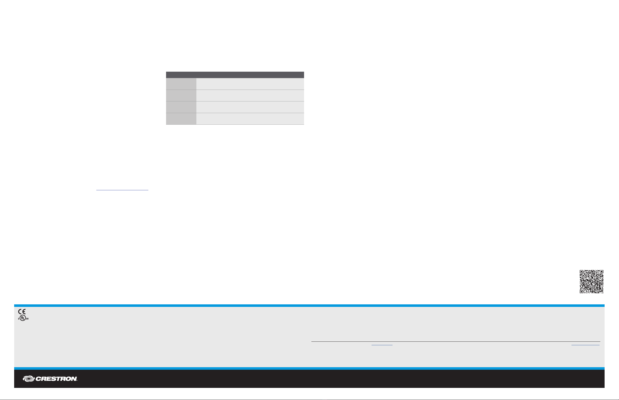
To manually select and activate the desired input, press one of the VGA
(1–4), HDMI (1–4), or DM (1–2) INPUT SELECT buttons. Refer to the
following table for a summary of the LED behavior of selected and
nonselected inputs.
NOTE: Manual selection of an input disables automatic switching. When
automatic switching is disabled, the AUTO LED turns off.
As of the date of manufacture, the product has been tested and found to comply with specications for CE marking.
This product is Listed to applicable UL Standards and requirements by Underwriters Laboratories Inc.
Federal Communications Commission (FCC) Compliance Statement
This device complies with part 15 of the FCC Rules. Operation is subject to the following two conditions:
(1) This device may not cause harmful interference, and (2) this device must accept any interference received, including interference that may cause undesired operation.
Caution: Changes or modications not expressly approved by the manufacturer responsible for compliance could void the user’s authority to operate the equipment.
Note: This equipment has been tested and found to comply with the limits for a Class B digital device, pursuant to part 15 of the FCC Rules. These limits are designed to provide reasonable protection against harmful interference in a residential
installation. This equipment generates, uses and can radiate radio frequency energy and, if not installed and used in accordance with the instructions, may cause harmful interference to radio communications. However, there is no guarantee that
interference will not occur in a particular installation.
If this equipment does cause harmful interference to radio or television reception, which can be determined by turning the equipment off and on, the user is encouraged to try to correct the interference by one or more of the following measures:
• Reorient or relocate the receiving antenna
• Increase the separation between the equipment and receiver
• Connect the equipment into an outlet on a circuit different from that to which the receiver is connected
• Consult the dealer or an experienced radio/TV technician for help
Industry Canada (IC) Compliance Statement
CAN ICES-3(B)/NMB-3(B)
Rack Mounting Safety Precautions
• Elevated Operating Ambient Temperature: If installed in a closed or multi-unit rack assembly, the operating ambient temperature of the rack environment may be greater than room ambient temperature. Therefore, consideration should be
given to installing the equipment in an environment compatible with the maximum ambient temperature (Tma) specied by the manufacturer.
• Reduced Airow: Installation of the equipment in a rack should be such that the amount of airow required for safe operation of the equipment is not compromised.
• Mechanical Loading: Mounting of the equipment in the rack should be such that a hazardous condition is not achieved due to uneven mechanical loading.
• Circuit Overloading: Consideration should be given to the connection of the equipment to the supply circuit and the effect that overloading of the circuits might have on overcurrent protection and supply wiring. Appropriate consideration of
equipment nameplate ratings should be used when addressing this concern.
• Reliable Earthing: Reliable earthing of rack-mounted equipment should be maintained. Particular attention should be given to supply connections other than direct connections to the branch circuit (e.g., use of power strips).
The specic patents that cover Crestron products are listed at patents.crestron.com. The product warranty can be found at www.crestron.com/warranty.
Crestron, the Crestron logo, 3-Series, .AV Framework, Cresnet, Crestron Toolbox, DigitalMedia, DM 8G+, and V T Pro-e are either trademarks or registered trademarks of Crestron Electronics, Inc. in the United States and/or other countries. Apple and iPad are either trademarks or registered trademarks
of Apple Inc. in the United States and/or other countries. HDBaseT and the HDBaseT Alliance logo are either trademarks or registered trademarks of the HDBaseT Alliance in the United States and/or other countries. HDMI and the HDMI logo are either trademarks or registered trademarks of HDMI
Licensing LLC in the United States and/or other countries. UL and the UL logo are either trademarks or registered trademarks of Underwriters Laboratories, Inc. in the United States and/or other countries. Other trademarks, registered trademarks, and trade names may be used in this document to refer
to either the entities claiming the marks and names or their products. Crestron disclaims any proprietary interest in the marks and names of others. Crestron is not responsible for errors in typography or photography.
This document was written by the Technical Publications department at Crestron.
©2015 Crestron Electronics, Inc.
DO Learn More
Check the website for additional information
and the latest rmware updates.
Crestron Electronics
15 Volvo Drive, Rockleigh, NJ 07647
888.CRESTRON | www.crestron.com
1. The DM IN and DM OUT ports are PoDM (Power over DM) and PoH (Power over
HDBaseT) PSE (Power Sourcing Equipment) ports. Any wiring that is connected to a PoDM
or PoH PSE port is for intra-building use only and should not be connected to a line that
runs outside of the building in which the PSE is located.
COLOR DESCRIPTION
Solid green The input is the active selection, and an incoming signal
is detected.
Flashing green The input is the active selection, and an incoming signal
is not detected.
Solid amber The input is not the active selection, and an incoming
signal is detected.
Off The input is not the active selection, and an incoming
signal is not detected.


