Sonomed E-Z Scan AB5500 Plus User manual

Table of Contents
1. Preface…………………………………………………………………………………….. 3
1.1 EZ-Scan B5500+……………………………………………………………………….3
1.2 EZ-Scan A/B5500+…………………………………………………………………… 3
2. Theory of Operation………………………………………………………………………4
2.1 A-Scan Function…………………………………………………………………….… 4
2.2 B-Scan Function…..………………………………………………………………….. 4
3. System Components……………………………………………………………………….5
4. System Specifications……………………………………………………………………...6
4.1 Regulatory Requirements………………………………………………………………6
4.2 Safety Regulations……………………………………………………………………..6
4.3 Environmental Conditions……………………………………………………………..6
4.4 Physical………………………………………………………………………………...6
4.5 Electrical……………………………………………………………………………….6
4.6 Interface……………………………………………………………………………….. 6
4.7 Probes…………………………………………………………………………………..6
4.8 Display…………………………………………………………………………………6
4.9 Printer…………………………………………………………………………………..7
5. A-Scan System Specifications……………………………………………………………. 8
5.1 Calibration…………………………………………………………………………….. 8
5.2 Capture Modes…………………………………………………………………………8
5.3 Examination Modes……………………………………………………………………8
5.4 Typical Ultrasound Intensities in Tissues……………………………………………...8
5.5 A-Scan Waveform Processing…………………………………………………………8
5.6 Statistical Analysis……………………………………………………………………. 8
5.7 IOL Analysis………………………………………………………………………….. 8
5.8 IOL Calculations……………………………………………………………………….8
5.9 Measurement Accuracy……………………………………………………………….. 8
5.10 A-Scan Amplifier……………………………..………………………………………8
5.11 User Profiles………………………………………………………………………… 8
5.12 General Specifications/Features………………………………………………………8
6. B-Scan System Specifications……………………………………………………………. 10
6.1 Examination Modes.………………………………………………………………….. 10
6.2 Display Scale………………………………………………………………………….. 10
6.3 Probe……………………………………………………………………………………10
6.4 Measurements……………..…………………………………………………………...10
6.5 Amplifier……………………………………………………………………………….10
6.6 Magnification…………………………………………………………………………..10
6.7 Display Resolution……………………………………………………………………..10
6.8 Processing……………………………………………………………………………...10
6.9 Freeze…………………………………………………………………………………..10
6.10 Image………………………………………………………………………………….10
6.11 Gray Scale…………………………………………………………………………….10
6.12 Display………………………………………………………………………………..10
6.13 Typical Ultrasound Intensities in Tissues…………………………………………….10
6.14 General Specifications/Features………………………………………………………10
7. Trouble Shooting B5500+…………………………………………………………………11
7.1 Factor Defaults Reset………………………...……………………………………….. 11
7.2 Touch Screen Calibration...…………………………………………………………… 13
7.3 RGB Fill………………………………………………………………………………..14
7.4 Video Output…………………………………………………………………………...14
7.5 Joystick Alignment……………………………………………………………………. 15
7.6 Rotary Encoder………………………………………………………………………...15
7.7 System Information…………………………………………………………………….16
7.8 Mixed Pattern Test……………………………………………………………………..16
5550-A-1903-2A page
1

Table of Contents, con’t.
7.9 Cal Pattern Distance Test………………………………………………………………19
7.10 Cal Pattern Area Test…………………………………………………………………20
7.11 Losing date, time and user information…..………………………………………….. 22
7.12 Unit does not turn on………………………………………………………………….23
7.13 Rear Connector Discriptions………………………………………………………….23
7.14 LCD Image is Upside Down………………………………………………………….23
8. Trouble Shooting A/B5500+……………………..………………………………………. 24
8.1 A-Scan Calibration………….……………………………………………………….…24
8.2 Measure………………………………………………………………………………...25
8.3 Losing date, time and user information…………………………………………….…. 25
8.4 A-Scan PCB……………………………………………………………………………26
8.5 A-Scan Probe Cable replacement……………………………………………………... 27
9. Routine Maintenance……………………………………………………………………...29
9.1 System General Inspection………………………………………………………….… 29
9.2 Enclosure Cleaning…………………………………………………………………... 29
9.3 Probes Cleaning……………………………………………………………………… 29
9.4 Storage……………………………………………………………………………….. 30
9.5 Probe general Inspection……………………………………………………………... 30
10. Unit Assembly…………………………………………………………………………….. 31
10.1 Top cover Bill of Materials…………………………………………………………...31
10.2 Top Cover Assembly Drawing………………………………………………………. 32
10.3 Bottom Cover Bill of Materials……………………………………………………… 33
10.4 Bottom Cover Assembly Drawing……………………………………………………34
10.5 Accessories Bill of Materials…………………………………………………………35
10.6 Accessories Drawings………………………………………………………………...36
11. Schematics………………………………………………………………………………… 37
11.1 Clock Generator………………………………………………………………………37
11.2 Front End Interface.…………………………………………………………………. 38
11.3 Power Supply………..………………………………………………………………. 39
11.4 Pulser Receiver……………………………………………………………………….40
11.5 Servo Controller………………………………………………………………………41
11.6 System Processor……………………………………………………………………..42
11.7 Video Interface………………………………………………………………………..43
11.8 Xilinx Configuration………………………………………………………………….44
11.9 Xilinx Power/Decouple……………………………………………………………….45
11.10 Xilinx RAM Interface……………………………………………………………….46
11.11 Xilinx Test Points…………………………………………………………………... 47
5550-A-1903-2A page
2

Preface
This manual is intended to provide
assistance in maintaining and repairing the
E-Z Scan 5500+ series of instruments
manufactured by Sonomed, Inc. For
additional technical assistance, please
contact Sonomed customer service at
1-800-227-1285.
General Description
The E-Z Scan 5500+ series is the latest
general ophthalmic biometry instrument
introduced by the industry leading Sonomed.
The series consists of two different models:
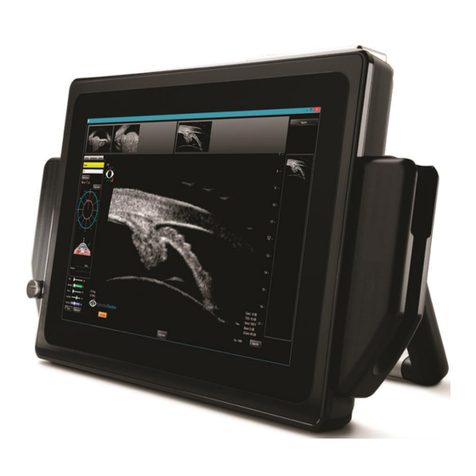
1.1 E-Z Scan B5500+
This B-Scan system allows for measuring a
two-dimensional image of an eye along one
plane.
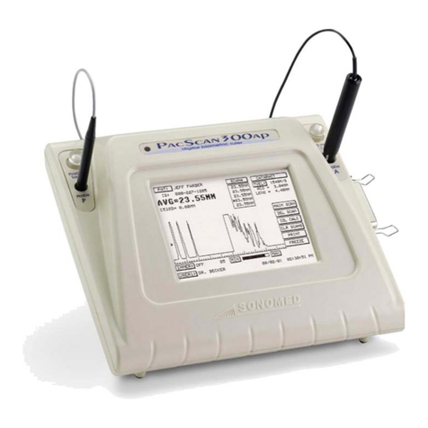
1.2 E-Z Scan A/B5500+
This A-Scan system allows for measuring
the axial length (AXL), anterior chamber
depth (ACD) and lens thickness of an eye
and for calculating the associated IOL power
for an implanted lens.
Both systems utilize a high-resolution
backlit touch screen liquid crystal display
(LCD) by which the user can enter
information and view data and calculations.
Adjustable legs can be tilted to several
angles for user comfort. After completion of
measurements and calculations, a hardcopy
may be obtained of the results using the
video printer.
5550-A-1903-2A page
3

2.1 A-Scan Function
One of the major applications of A-Scan is
to measure the axial length of the eye in
order to calculate the necessary power of an
intraocular lens replacement (such as
required in the treatment of cataracts).
In A-Scan, a beam of ultrasound is
transmitted along a fixed line through the
eye and the reflected echoes are displayed.
An echo is produced whenever the
ultrasound beam encounters a boundary
between two media having different values
of acoustic impedance. The acoustic
impedance is a function of density and
elasticity and the amount of energy reflected
depends upon the difference in the acoustic
impedance of the two media. A-Scan is
equipped with software that calculates the
distance between the echoes.
The probe acts as the interface between the
instrument and the patient. The probe
contains a piezoelectric crystal, which
converts electrical energy into ultrasound
when transmitting and then acts as a detector
to convert the received ultrasound echoes
into electrical signals for display and
measurement. The A-Scan probe contains a
red LED fixation light in its center. The
fixation light provides a target, which assists
the operator to align the visual axis of the
eye being examined. To minimize
indentation of the eye, which is caused by
the operator applying excessive pressure
while holding the probe on the eye, A-scan
probes feature "Soft-Touch". This feature
minimizes the compression effect by
allowing the probe handle to float on
bushings located inside the probe handle.
2.2 B-Scan Function
Theory of Operation The operation of the B-Scan is similar to a
radar operation. A short ultrasound wave is
produced by a transducer and sent to the
eye. Part of the energy of that wave is
reflected back to the transducer from various
structures of the eye (lens, retina, etc.). The
reflected energy is converted into electrical
signals that are amplified and displayed on
the LCD as an intensity. Since the reflected
energy is proportional to the reflected
properties of the different eye structures, one
can examine the eye by observing the
resulting grey or color scale image.
The ultrasound transducer is located in the
B-Scan probe and is driven by two (2)
solenoids to produce a 60°sector scan. The
sector scan is divided into 256 rays. The
data acquired along each ray is digitized at
512 discrete time intervals (pixels) and each
sample voltage is encoded into 7 bits of
information.
The acquired information is stored in one (1)
of the two (2) B-Scan memory buffers. At
any time during the acquisition, the content
on one memory buffer is displayed while the
other is updated with new data from the
amplifier.
The display control maps data in the
memory buffer onto the LCD screen, thus
showing sector scans. The microprocessor
periodically checks touch screen controls
and calculates mapping coefficients, to pan
the image.
There is a simultaneous vector display that
shows the signal along a selected ray,
represented as an amplitude waveform. This
supplemental information enables the doctor
to differentiate between the two (2) signals
that have the closest intensities of grey.
Doc# 0300-1903-3A page 4
This manual suits for next models
1
Table of contents
Other Sonomed Medical Equipment manuals
Popular Medical Equipment manuals by other brands

Getinge
Getinge Arjohuntleigh Nimbus 3 Professional Instructions for use

Mettler Electronics
Mettler Electronics Sonicator 730 Maintenance manual

Pressalit Care
Pressalit Care R1100 Mounting instruction

Denas MS
Denas MS DENAS-T operating manual

bort medical
bort medical ActiveColor quick guide

AccuVein
AccuVein AV400 user manual


