Sonomed VuPad User manual
OPERATOR’S MANUAL

2
CONTENTS
OVEVIEW
4
Description
Indications for Use
Contraindications
GETTING STARTED
6
System Components
Unpacking
Consideration When Joining Network Domain
Opening Display and Set-Up
A-SCAN
11
Patient Database
Exam Mode
Verify Calibration
Exam Mode
Calculation Mode
Reports
DIAGNOSTIC A-SCAN
16
PACHYMETRY
19
Select Exam Mode
Perform Exam
Report
B-SCAN AND UBM
22
Configure System
Patient Database
Exam Mode
MAINTENANCE
27
Cleaning and Disinfection
SPECIFICATIONS
31
A-Scan Specifications
UBM / B-Scan Specifications
Pachymeter Specifications
General Specifications
ALARA and Emissions
Immunity Test Levels
WARNINGS AND CAUTIONS
47
CYBER SECURITY RECOMMENDATIONS
50
WARRANTY
52
SYMBOLS
54

3
CONTACT INFORMATION
Sonomed, Inc.
1979 Marcus Avenue, C105
Lake Success, NY 11042, U.S.A.
Tel: 800-227-1285
Tel: 516-354-0900
Fax: 516-354-5902
www.sonomedescalon.com
Authorized Representative for Medical Devcie Directive:
Emergo Europe
Prinsessegracht 20
2514 AP The Hague
The Netherlands
Tel: +31 (0)70-345-8570
Fax: +31(0) 70-346-7299
United States Federal law and European regulations restrict this device to use
by, or on the order of, a physician. This device should only be used under the
supervision of an experienced ophthalmic medical practitioner in a clinical
setting. Before examining a patient, the user should become acquainted with
the operating procedures, warnings and precautions set forth in the Operators
Manual. The user should consult additional resources as necessary for further
information regarding the proper application of ultrasound technology. If
difficulty is experienced when operating the unit after carefully reviewing this
Operators Manual, contact your local Sonomed Escalon distributor for
assistance
This instrument should be used in strict accordance with the instructions
outlined in this Operators manual. The safety of the operator and the
performance of the instrument cannot be guaranteed if used in a manner not
specified by Sonomed Escalon.
Do not use the device together with HF surgical equipment. HF surgical
equipment may be damaged, which may result in fire.
There are no user-serviceable parts within the VuPad system.
To receive a translated copy of this manual, contact your in-country distributor,
or call Sonomed directly at 516-354-0900 or 800-227-1285. For technical
service and support please contact Sonomed Escalon or your local distributor.
Document No. 5575-1901-E, Aug 2019

4
OVERVIEW
DESCRIPTION
The VuPad™ is an ophthalmic ultrasound system capable of utilizing a range of
transducer frequencies for optimized imaging and measurements of various
ophthalmic structures. The device is a multi-purpose system intended for use
in ophthalmic applications designed to capture images of the interior of the eye
and make accurate measurements of the structures.
The VuPad™ is a stand-alone system that runs on a Windows 10 platform and
may be networked (by the user) for interface with electronic medical records
systems, printing, and other purposes. The system consists of the VuPad™
console, ultrasound probe(s) and transducer(s), and foot pedal.
The device is used by coupling the probe/transducer to the eye either through
direct contact or immersion methods. Available modes are biometric A-scan,
pachymeter, diagnostic A-scan, B-scan, UBM (ultrasound bio-microscope).
Biometric A-Scan
A-Scan is a noninvasive tool that produces length measurements along the
visual axis of the eye for calculation of intraocular lens power. This method
enables precise measurement of the anterior chamber depth (ACD), lens (L),
and vitreous to produce the axial length of the eye. When a cataract is
removed, the lens is replaced with an artificial lens implant. By measuring both
the axial length of the eye (A-scan) and the power of the cornea (keratometry),
a user selected formula can be used to calculate the power of the intraocular
lens needed.
Pachymeter
Pachymeter is a noninvasive tool that produces measurements of the thickness
of the eye’s cornea. It is used to perform corneal pachymetry prior to refractive
surgery, for keratoconus screening, limbal relaxing incisions surgery and is
useful in screening for patients suspected of developing glaucoma among other
uses.

5
Diagnostic A-Scan
Diagnostic A-Scan is a noninvasive tool that enables diagnostic evaluation of
detected eye pathologies found with B-Scan screening. This method enables
imaging of structural amplitudes for analytical determination of the patient’s
eye disorder.
B-Scan
B-Scan is a noninvasive tool that produces a cross-section, two-dimensional
grayscale images for diagnosing pathologies of the posterior segment of the
eye. This method enables imaging when the light-conducting media of the eye
are opaque. Common conditions such as cataract, vitreous degeneration,
retinal detachment, ocular trauma, choroidal melanoma, and retinoblastoma
can be accurately evaluated with this modality.
UBM/ Ultrasound Bio-Microscopy (UBM-Mode)
UBM is a noninvasive tool that produces high resolution cross-section, two-
dimensional grayscale images of the anterior segment of the eye. This method
enables imaging of structural details such as Bowman's membrane, stroma,
cornea, anterior chamber, lens, iris, ciliary body, and scleral spur. Other
parameters such as iris area and volume, angle opening distance, angle recess
area, sclera thickness, and trabecular meshwork-ciliary process can be
evaluated and measured. Common conditions such as glaucoma, iris cyst,
neoplasms, trauma and foreign bodies can be accurately identified
INDICATION FOR USE
The VuPad™ is intended to be used to visualize and measure the eye and orbit
using B-Scan and A-scan ultrasound.
CONTRAINDICATIONS
The VuPad™ is not intended for fetal use.
6
GETTING STARTED
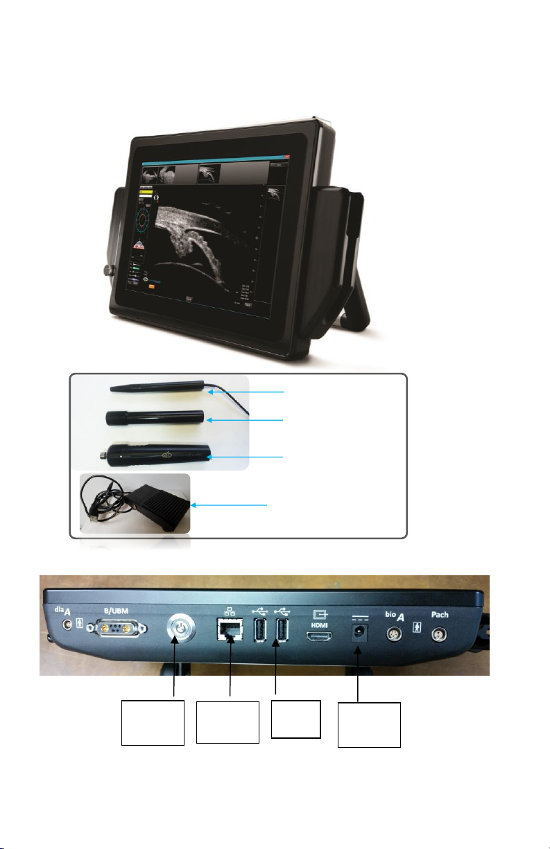
SYSTEM COMPONENTS
PROBES
B-Probe
(12 or 20 MHz Probes)
Water Path Probe
(with 35 or 50 MHz Transducers)
A-Probe 10 MHz
Foot Pedal
Power
On/Off
Ethernet
USB
Power
Cable

7
UNPACKING
①Unpack contents from packaging.
②Connect power cord between console and wall outlet.
NOTE: Console may be propped on its stand or attached to a VESA
mount.
CAUTION: Position such that console is well ventilated with easy
access to disconnect power cords, as may be necessary.
③Connect the probe cables to unit and place probes into probe holders.
NOTE: The same cable is used for all B-scan and UBM probes.
④Power on console. System will boot up into a Windows 10 home screen
and the VuPad icon can be selected to launch the program.
NOTE: Console may be powered off by pushing the power button.
CONSIDERATION WHEN JOINING TO
NETWORK DOMAIN
The Vupad uses Windows 10 and may be joined to (or removed from) a
network domain. However, when doing so, it is required that the local user
account is set up as a local administrator on the ultrasound system.
One potential issue to keep in mind is that when an ultrasound system is joined
to a domain, the domain rules are typically pushed down, which can prevent a
local user account from having full permissions (this would result in the
ultrasound system not functioning properly). Please ensure that the local user
account is set up as an administrator on the ultrasound system via your domain
rules (i.e. the local user must remain as the local administrator).
For questions, please contact technical service at 516-354-0900 or
800-227-1285 or email ultrasound-support@escalonmed.com.

8
OPENING DISPLAY AND SETUP
①OPEN THE VUPAD PROGRAM by clicking on the VuPad Icon located on the
desktop screen.
② CLICK ON THE “CONFIGURE” TAB. This will allow the user to set up defaults
for the MD/Examiner by:
* Select “New MD/Examiner” tab and complete the requested information
for MD/Examiner using the on-screen keyboard (or optional external
Bluetooth keyboard). (see Fig. 1)
* The user can also designate any user as the “Default Examiner” or
“Default Attending” (required for Biometric a-scans) by selecting the
appropriate tab(s).
* The preferred lenses (IOL’s) can be selected by selecting the “Lenses” tab
on the user setup screen. Pressing “ADD” will display a window
showing Lens Manufacturers on the left and lenses produced by that
manufacturer in the center of the display. Once a lens is selected, the
“ADD” key will become active and selecting this key will add the
desired lens to the users preferred list. (see Fig. 2)
* Once all information has been entered, pressing the “OK” will return the
user to the Lens screen. [Verify that the newly selected lens(s) appear
in the table. Pressing “Close” will now return the user to the “M/D
Examiner” screen.
* Pressing “Close” will return the user to the Patient Database screen.
NOTE: The above procedure can be used to enter any number of additional
users so that each individual user can select their preferred lenses, etc.

9
Fig. 1
Examiner Lens Selection
Master Lens Database Tab
MD/Examiner Setup Display:
Name: Enter Examiner Name
Type: Enter Examiner/Attending Phys./ Referring Phys.
Default Examiner: A “default” examiner can be entered for
every exam.
NOTE: In order to perform A-scan biometry measurements, an
“Attending” physician must be entered. Selecting a
“Default Attending” will automatically assign this user
for each exam.

10
Fig. 2
Lens Selection Screen:
Manufacturer: Scroll and Select the Lens Manufacturer’s Name.
Lenses: Scroll and Select the desired Lens Model.
NOTE: The “Lens Database” Tab (see Fig.1) includes over 1500
lenses and associated data which the user can update, by
adding, deleting or editing lenses.
The “LENSES” Tab is the Examiner Lens Selection tab from which
the Examiner must choose the desired lenses from for
performing IOL calculations.

11
A-SCAN
PATIENT DATABASE
①PATIENT: Select the “NEW”tab located at the top left side of the database
display screen.
NOTE: For previously entered patient, scroll through patient list, by sliding
the scroll indicator just to the right of patient list until the desired patient
name is displayed.
②ENTER NEW PATIENT Information into the appropriate fields (see Fig. 3)
[Note: K-readings can be entered here or later if performing a-scan
biometry.]….. Press “OK”
Fig. 3
EXAM MODE
①EXAM: Select the “NEW” tab located at the top right side of the database
display screen.
②Verify Examiner [Required], Attending Phys [Required], and Referring
Phys (if needed) are entered.

12
③ENTER THE EXAM TYPE [Bio A] and Laterality [OD/OS]. [If the exam is to be
used as a teaching case, place a checkmark in the box labeled “Teaching
Case”]. Press “OK”
④ENTER PARAMETERS: K-readings can be entered for either/both eyes. If
the patient has had previous refractive surgery, pressing the “Post
Refractive” tab will allow the user to select the formula and IOL Correction
[Aramberri Double K, Latkany Myopic/Hyperopic] to apply to the lens
power calculation. Then select the “OK” tab.
VERIFY CALIBRATION
① The Verify Calibration Window should be displayed if the “Bio A” tab had
been selected previously.
- Select YES to perform the calibration verification. The VuPad will
start emitting an audio “beeping”. Place a drop of water onto the face of
the a-scan probe and press the probe onto the calibration cylinder (located
on left side probe holder). Once the correct pattern is accepted by the
instrument, the beeping will stop and the message “Calibration Verified”
will appear.
[Note: It may be necessary to increase the “Gain” control in order to
achieve the desired pattern].
-Select NO to bypass the calibration verification procedure.
EXAM MODE
①Select the desired OD/OS tab located on the top of the display. Then
proceed as follows: (see Fig. 4)
*SCAN Tab: Select the desired mode (Cataract, Aphakic, etc.) for the eye to be
examined. The user can also select “immersion” mode if using an
Immersion Shell for biometry.
* BIOMETRY Tab: will display the collected data as the scans are performed
and accepted.
* SETTINGS tab: will display the various velocities used for the selected mode.
The user can adjust these values if needed by using the ▲/▼ symbols.

13
Fig. 4
- The “CONTINUOUS CAPTURE” tab, if selected, will allow the user to set
the desired number of scans that the VuPad will obtain with a single press
of the footswitch. If “Immersion” mode has been selected, TWO footswitch
presses would be required to begin obtaining scans –once to activate the
transducer for alignment and one to activate the algorithm for scan
acceptance.
* HISTORY tab: records all previous a-scan exams [Date/Time/ Exam type] for
the selected patient.
②For “Direct Contact”scanning, press the “START SCAN”tab at the bottom
of the display (or press the footswitch). The VuPad will emit a continuous
beeping sound indicating that the scan mode has been activated. Place the
probe in contact with the cornea and instruct the patient to look at the
RED FIXATION light at the tip of the probe. Once the proper alignment is
achieved, the VuPad will begin to accept scans which will be shown on the
right side of the display screen. Once the desired number of scans are
accepted, the VuPad will cease emitting the beeping sound.
For “Immersion” scanning, the user should press the “ALIGN PROBE” tab
(or footswitch) until alignment is achieved. Once the user is satisfied that
the probe is properly aligned, pressing the “START SCAN” tab (or
footswitch a second time) will activate the scanning algorithm and begin to
collect scan data.
A-scan
Calculations
Reports

14
③Selecting the BIOMETRY tab, will permit the user to view all the data
collected from the scan session including the ACD, LENS THICKNESS,
VITREOUS DEPTH AND AXIAL LENGTH for all scans in the set.
-The user can omit a scan from being included in the Average by un-
checking the “Enabled” box located to the left of each data set. This
does not delete the scan from the record.
-The user can “Delete” a scan from the record by selecting and holding
the individual scan data (for approximately 2 seconds) located on the
right side of the display and selecting “delete” from the pop-up menu.
This will delete the scan and all associated data from the record.
CALCULATION MODE
Once the user has reviewed and is satisfied with the scan results, the
CALCULATIONS tab, located at the top of the measurement display screen,
should be selected. (See Fig. 4)
① Enter the “Target” refraction and K-readings (if not entered previously)
② Average AXL and ACD should populate based on previous screen.
③ LINK tab will enable to user to display the same Formula or the same Lens
for all 4 of the calculation tables.
④ LENS can be selected from the drop-down menu which will include all lens
models previously added to user profile.
⑤ Formulas can be selected from the drop down menu which will include all
formulas previously added to profile.
⑥ IOL table will display with the “Target” refraction entered previously at the
center. The user can edit the center value by changing the value in the
“Target” refraction field. (step 1 above).
⑦ Once all values are approved and accepted, the user should select the
“ADD TO REPORT” tab located on the bottom right of the display.
⑧ If the fellow eye is also to be measured and included onto the report the
user should select either the OD or OS tab at the top of the display and
repeat the measurement/calculation steps described above.
⑨ Once the eye(s) is measured, calculations performed and “ADDED TO
REPORT” the REPORT tab located at the top of the display should be
selected.

15
REPORTS
Once the REPORT tab is selected, the display will show the report template (see
Fig. 5) which includes the A-scan(s) and IOL calculations for each eye for which
the measurement/calculations were performed. If required, the user can return
to the calculation tables, edit the lens and/or formula data and select the ADD
TO REPORT tab again. This will generate a second page to the report which will
now display 2 of 2, 3 of 3, etc…..
INCLUDE HEADER: If this tab is highlighted, the default header
[SonomedEscalon] will be displayed. Deselecting this tab will cause the
Header to be removed from the report.
REMOVE PAGE: Highlighting this tab will remove the currently displayed page
from the report.
PRINT: Selecting this tab will display the Windows print window to appear from
which the user can select any of the installed printers.
EXPORT: Selecting this tab will display the Export pop-up window to appear for
selection of export format by the user.
Press “CLOSE EXAM” when finished to return to the patient database screen.
Fig. 5
16
DIAGNOSTIC A-SCAN MODE
① Power ‘On’ System: By pressing the front panel power switch located on
the bottom right side of the unit’s front panel.
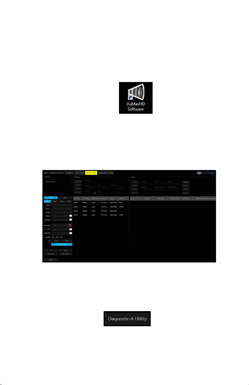
②Starting Application: From Windows desktop, double click on the
‘VuMaxHD Software’ icon (Fig. 6).
Fig. 6 - VuMAX HD Software Icon
③Patient Database Screen: Upon launching the application the ‘Patient
Database’ screen (Fig. 7) will display. Here you can add a new patient or find
previously performed exams.
Fig. 7- Patient Database Screen
④Diagnostic A-Utility: To start the Diagnostic A-Scan application, select the
‘Diagnostic A-Utility’ button (Fig. 8).
Fig. 8 - ‘Diagnostic-A Utility’ Button
17
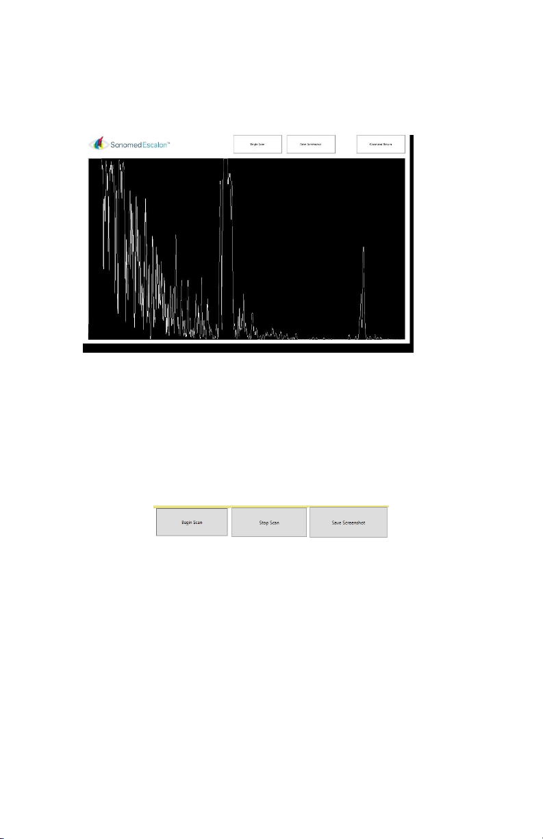
⑤Application Window: Upon selecting the ‘Diagnostic-A Utility’ button the
VuMAX HD patient database will momentarily close and the Diagnostic A-Scan
Utility screen will open (Fig. 9).
Fig. 9 - Diagnostic-A Utility Screen
⑥Begin Scan, Stop Scan and Save: To commence a live scan, select the
‘Begin Scan’ button. Upon selection an A-Scan trace will appear on the main
window. To stop scan, click on the correspondent icon as well as for save a
screenshot (Fig. 10)
Fig. 10-‘Begin Scan’ ‘Stop Scan’ and ‘Save” Buttons
⑦Save As: Upon selecting the ‘Save Screenshot’ button, a Windows ‘Save
As’ screen (Fig. 11) will be displayed. Navigate through the folders to select a
destination folder for saving the patient’s saved A-Scan. Note that a ‘File
Name’ is required for saving the document.

18
Fig. 11 ‘Save As’ Window
⑧Close and Return: Upon completing examination and saving a record of
the test, select the ‘Close and Return’ button to return to the VuMax HD
Patient Database screen.
⑨Calibration: Clicking on the Sonomed Escalon logo while having the
control key pressed, it will pop up the S curve calibration as in Fig.12.
Fig. 12 Calibration Screen Window

19
PACHYMETRY
SELECT EXAM MODE
①EXAM: Select the “NEW” tab located at the top right side of the database
display screen.
②Verify Examiner [Required], Attending Phys [Required], and Referring
Phys (if needed) are entered.
③ENTER THE EXAM TYPE [Pach] and Laterality [OD/OS]. [If the exam is to be
used as a teaching case, place a checkmark in the box labeled “Teaching
Case”]. Press “OK”
PERFORM EXAM
Fig. 13

20
① Select desired exam mode option: (Fig 13 and 14)
-Single Point | Single Reading Provides for a single reading at a single
point on cornea.
-Single Point | Multiple Readings Proides for up to 5 readings at a
single point on cornea.
-Multiple Points | Single Reading Provides for a single reading at up to
9 points on cornea.
-Multiple Points | Multiple Readings Proides for up to 5 readings at up
to 9 points on cornea.
Note: If multiple points are to be scanned, select appropriate location on
corneal map to first measure.
②Confirm Tissue Velocity is appropriate; tap to change as desired.
③Enter measured IOP if corrected IOP based on corneal thickness is desired.
④Select whether a single or multiple points should be automatically taken
once system scan criteria are met.
⑤Select “SCAN” button to start scan (or press foot pedal).
⑥Repeat, as necessary, to measure all desired points. Readings can be
cleared and repeated, if necessary.
Fig 14
Table of contents
Other Sonomed Medical Equipment manuals


Popular Medical Equipment manuals by other brands


Getinge
Getinge Arjohuntleigh Nimbus 3 Professional Instructions for use

Mettler Electronics
Mettler Electronics Sonicator 730 Maintenance manual

Pressalit Care
Pressalit Care R1100 Mounting instruction

Denas MS
Denas MS DENAS-T operating manual

bort medical
bort medical ActiveColor quick guide

AccuVein
AccuVein AV400 user manual


