Sonosax SX-M2D2 User manual


Table of Contents
1 Introduction...................................................................................................................................
1.1 Key Features.............................................................................................................. 6
1.2 Typical Applications....................................................................................................6
1.3 Functional Block Diagram...........................................................................................7
2 Panel Descriptions........................................................................................................................ 8
2.1 Front Panel................................................................................................................. 8
2.2 Rear Panel................................................................................................................. 8
2.3 Left Panel................................................................................................................... 9
3 Powering..................................................................................................................................... 10
3.1 Intelligent Power Management.................................................................................10
3.2 Power Sources.........................................................................................................10
3.3 Li-ion Battery............................................................................................................. 11
3.4 Li-ion Charger........................................................................................................... 11
3. Powering up the SX-M2D2.......................................................................................12
4 User Interface............................................................................................................................. 13
4.1 Interface Overview....................................................................................................13
4.2 Main Screen.............................................................................................................13
4.3 Menu Navigation.......................................................................................................1
4.4 Menu Tree................................................................................................................ 16
4. Main Menu................................................................................................................ 16
4.6 Inputs Menu..............................................................................................................17
4.7 Outputs Menu........................................................................................................... 19
4.8 PHONES, LINE OUT, AES OUT, USB OUT Menus..................................................19
4.9 Output Setup Menu.................................................................................................. 21
4.10 Reference Tone...................................................................................................... 21
4.11 Mixer Menu.............................................................................................................22
4.12 Mix Compressor/Limiter..........................................................................................22
4.13 System Menu..........................................................................................................23
4.14 Meters Menu...........................................................................................................23
4.1 Controls Menu........................................................................................................ 24
4.16 Sampling Frequency Menu.....................................................................................2
4.17 Display Menu..........................................................................................................26
4.18 Factory Default Menu............................................................................................. 26
4.19 Info Menu...............................................................................................................27
4.20 Presets Menu.........................................................................................................27
4.21 Power Menu........................................................................................................... 28
4.22 Power Setup Menu................................................................................................. 28
USB audio interface.................................................................................................................... 29
.1 Supported Hosts....................................................................................................... 29
.2 USB Application examples.......................................................................................29
6 Troubleshooting.......................................................................................................................... 30
6.1 [USB audio] no audio input on Microsoft Windows...................................................30
6.2 [USB audio] USB audio ERROR status....................................................................30
7 Service Mode.............................................................................................................................. 31
7.1 Entering the Service Mode.......................................................................................31
7.2 Firmware Update......................................................................................................31
7.3 Configuration Reset..................................................................................................32
7.4 Test Interface Menu..................................................................................................32
8 Specifications............................................................................................................................. 33
8.1 IN1/IN2 Microphone Preamplifier..............................................................................33
8.2 Digital Domain..........................................................................................................33
8.3 Line Output............................................................................................................... 33
8.4 Phones Output..........................................................................................................34
8. Power....................................................................................................................... 34
8.6 Operating Conditions................................................................................................34
8.7 Mechanical............................................................................................................... 3
9 Connector Pin Assignments........................................................................................................ 36
9.1 Mic/Line analog input (TA-3M)..................................................................................36
9.2 Line output (TA-3M)..................................................................................................36
SX-M2D2+ User Manual 2/37

9.3 AES input/output (TA-3M).........................................................................................36
9.4 Phones 3. mm jack.................................................................................................. 36
9. Power Hirose 4-pin................................................................................................... 36
9.6 USB Audio................................................................................................................36
9.7 USB Power............................................................................................................... 37
SX-M2D2+ User Manual 3/37

Revision History
Revision Date Description
1.0 October 2019 Initial release
1.1 January 2020 Updated to firmware revision 1.1
Fixed document links
1.2 May 2020 Updated to firmware revision 1.2
Le al Notices
Product specifications and features are subject to change without prior notification.
Notes / Warnin s
NOTE
A NOTE provides additional or special information to assist operation
and maintenance personnel
WARNING
A WARNING indicates material to which the reader should play close
attention
Compliances
WEEE Statement
This product is classed as electrical or electronic equipment
within the meaning of the Waste Electrical and Electronic
Equipment (WEEE) Directive 2002 / 96 / EC and must not
be disposed of in domestic household waste.
RoHS
Sonosax complies fully with Restriction of the Use of Certain
Hazardous Substances in Electrical and Electronic
Equipment (RoHS)
SX-M2D2+ User Manual 4/37

1 Introduction
Congratulations! In choosing the SX-M2D2, you have just purchased a very high
quality audio device, the result of the hard work of a team of renowned engineers. For
more than forty years, Sonosax recorders and mixers have been recognized by
professionals around the world for their outstanding technical features and unmatched
musicality.
The tool which you hold in your hands is the latest addition to the range, concentrating
all the brand's know-how into an ultra miniaturized case. It is:
•A very high quality stereo preamplifier
•An analog-to-digital and digital-to-analog converter
•A headphone and monitoring amplifier
•A USB sound card compatible with any type of computer or smartphone
•An audio mixer with integrated compressor-limiter.
An embedded digital matrix allows any input to be routed to any output or to an
internal stereo mixer. The fully digital controls allow menu access to all features with
only two rotary encoders. A high-brightness graphic display shows the available
options and settings as well as four modulometers assignable in pairs to any signal
source. The power supply from a standard battery, recharged in the device,
guarantees hours of autonomy, even if the two power sources available to the SX-
M2D2 are unavailable.
As with all SONOSAX products, the SX-M2D2 is built without any compromise in
quality, using only the best components available and passes stringent quality
controls.
The information and instructions contained in this manual are necessary to ensure
safe operation of your equipment and to maintain it in good working condition; please
read it carefully.
SX-M2D2+ User Manual /37
1.1 Key Features
Inputs / Outputs
•Two mic/line analog inputs with 13 dB dynamic range
•Independent line and headphone outputs
•AES42/AES3 input, AES3 output
•Two Input / Two Output USB audio 2.0 interface (sound card)
•Internal audio matrix allowing complex routing of any input to any output
•Internal six input mixer with fully configurable compressor-limiter
•Powered by removable Li-ion battery, Hirose or USB with intelligent energy
management
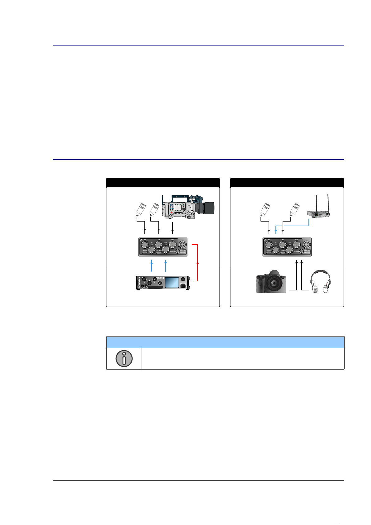
1.2 Typical Applications
2 channels A/D + D/A extension box Preamplifer for Camera
AES
RX1 RX2
PHONES
POWER
IN2
OUT
IN1
AUDIO
IN
AES
AES
OUT
9-18V DC
SN XXXX
PHONES
POWER
IN2
OUT
IN1
AUDIO
IN
AES
AES
OUT
9-18V DC
SN XXXX
PWR
AES
NOTE
See USB Application examples at page 29.
SX-M2D2+ User Manual 6/37

1.3 Functional Block Dia ram
The SX-M2D2 overall block diagram consists of the following:
•2 mic/line inputs with +20dB pre-gain, dual ADC converters, Low Frequency
cut and gain stage
•AES42/AES3 digital input with Asynchronous Sample Rate Converter (ASRC)
and gain stage
•USB audio interface with ASRC
•Phones, Line and AES outputs (AES with its own clock domain)
•Power Supply Unit (PSU)
•6 to 2 channels mixer (MIX) with compressor/limiter
•4x 2 channel output monitoring (MON)
•2 or 4 channels meters
•User Interface: 2 rotary encoders with push buttons and OLED screen
USB
AUDIO
CLASS 2.0
AES OUT
ADC
ADC
0 / +20 dB
ASRC
ASRC
DAC PHONES
DAC
IN 1
IN 2
AES3
AES42
USB
AUDIO
HIROSE DC IN
9-18V
USB POWER
186 0 LI-ION
REMOVABLE
CELL
PSU
DSP
DUAL-ADC INPUTS
DC/DC
CHARGER
BATTERY GAUGE
D-ADC LF CUT
D-ADC LF CUT
MIX
ASRC
IN1
IN2
AES1
AES2
USB1
USB2
MIX1
MIX2
LINE OUT
METERS
MON
MON
AES
RX
AES
TX
MON
MON
ASRC
POWER
MANAGEMENT
MON
2CH
2CH
2CH
2CH
MIC1
MIC2
AES2
AES1
USB1
USB2
MIX1
MIX2
REF TONE
LEFT
RIGHT
OUTPUT
LEVEL
MIX
MIX L
MIX R
COMPRESSOR
OUTPUT
LEVEL
MIC1 2CH
2CH
2CH
MIC2
AES2
AES1
USB1
USB2
MANAGEMENT
AUDIO
USER INTERFACE
INTERFACE
USER
MONO
STEREO
REV-STEREO M/S
--- (NONE)
1 -> L 1 -> C 1 -> R
2 -> L 2 -> C 2 -> R
SX-M2D2+ User Manual 7/37
2 Panel Descriptions
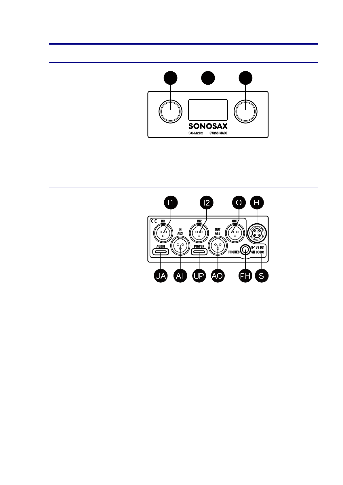
2.1 Front Panel
PL PRD
PL, PR
Left and right rotary encoders with push-
button
D
OLED display
2.2 Rear Panel
I1
I2
O
H
PH
UA
UP
AI
AO
S
I1, I2
Mic/Line analog audio input on TA-3M
O
Line analog audio output on TA-3M
H
External DC input on Hirose 4-pin
S
Serial number marking
UA
USB audio 2.0 on USB type C
UP
External VDC input on USB type C
AI, A0
AES audio input/output on TA-3M
PH
Headphone audio output on 3. mm jack
SX-M2D2+ User Manual 8/37

3 Powerin
3.1 Intelli ent Power Mana ement
The SX-M2D2's intelligent power management is a combination of hardware and
software which optimizes the distribution and use of electrical power.
It includes the following:
•High efficiency current limited switching power supplies with automatic load
prioritization
•Automatic battery charger, low-voltage battery pre-conditioning, detection of
faulty cells and thermal monitoring for charging pause in case of overheating
•Ultra low standby current
•Removable battery charge state and voltage measurement
•Under-voltage automatic power-down
•Smart load shedding, which shuts down unused inputs and outputs
•Display auto-off
3.2 Power Sources
The SX-M2D2 has two external power connectors and an integrated battery.
The battery must be present in the device to ensure that all functions are always
available.
These sources are independent and can be used simultaneously to prevent a power
failure.
When a power source is disconnected (or fails), the SX-M2D2 automatically switches
to an available power source.
This list reflects the SX-M2D2 power sourcing priority:
1. Hirose 4-pin connector
2. USB Power connector
3. Removable Li-ion battery cell
NOTE
USB Power input can drain up to 1.3A
WARNING
The battery must be present in the device to ensure that all functions are
always available.
The SX-M2D2 can be powered by an external source, without a battery
for a few moments when replacing a discharged battery with a charged
one.
SX-M2D2+ User Manual 10/37
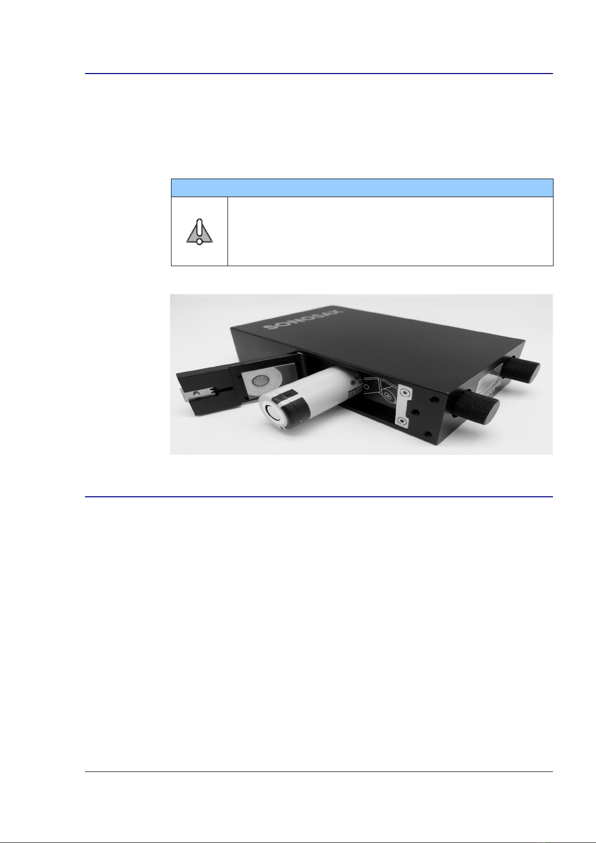
3.3 Li-ion Battery
The SX-M2D2 is designed to use 186 0 Li-ion cells that meets the following
specification:
•Nominal voltage: 3.6V
•Charging (float) voltage: 4.2V
•Length: 6 mm (unprotected)
The Panasonic NCR186 0B is the reference battery model for the SX-M2D2.
WARNING
•Avoid to use batteries from a non-safe supplier
•Never use batteries with a charging voltage below 4.2V
•Protected batteries with length > 6 mm do not fit into the SX-
M2D2
Insert the battery in the SX-M2D2 with the ‘+’ polarity visible.
3.4 Li-ion Char er
The SX-M2D2 has an integrated Li-ion battery charger. When Hirose or USB DC
power is applied, the charger will operate.
The Li-ion charger will charge the internal battery with a current max of 00mA or 1A
(user adjustable). As the charger operates in both standby and active mode, the real
charge current depends on the SX-M2D2 power consumption.
When using the USB power input, the maximum current over USB is 1.3A (6. W). If
less power is required by the SX-M2D2, the charger is enabled. If more power is
required, the internal battery will be used and start to be discharged.
SX-M2D2+ User Manual 11/37

3.5 Powerin up the SX-M2D2
To power-up the SX-M2D2, press and hold both rotary encoders until the splash
screen appears (2-3 seconds).
SX-M2D2+ User Manual 12/37
4 User Interface
4.1 Interface Overview
The SX-M2D2 user interface is composed by two rotary encoders and a 128x64 pixels
OLED display. Both rotary encoders include push-buttons.
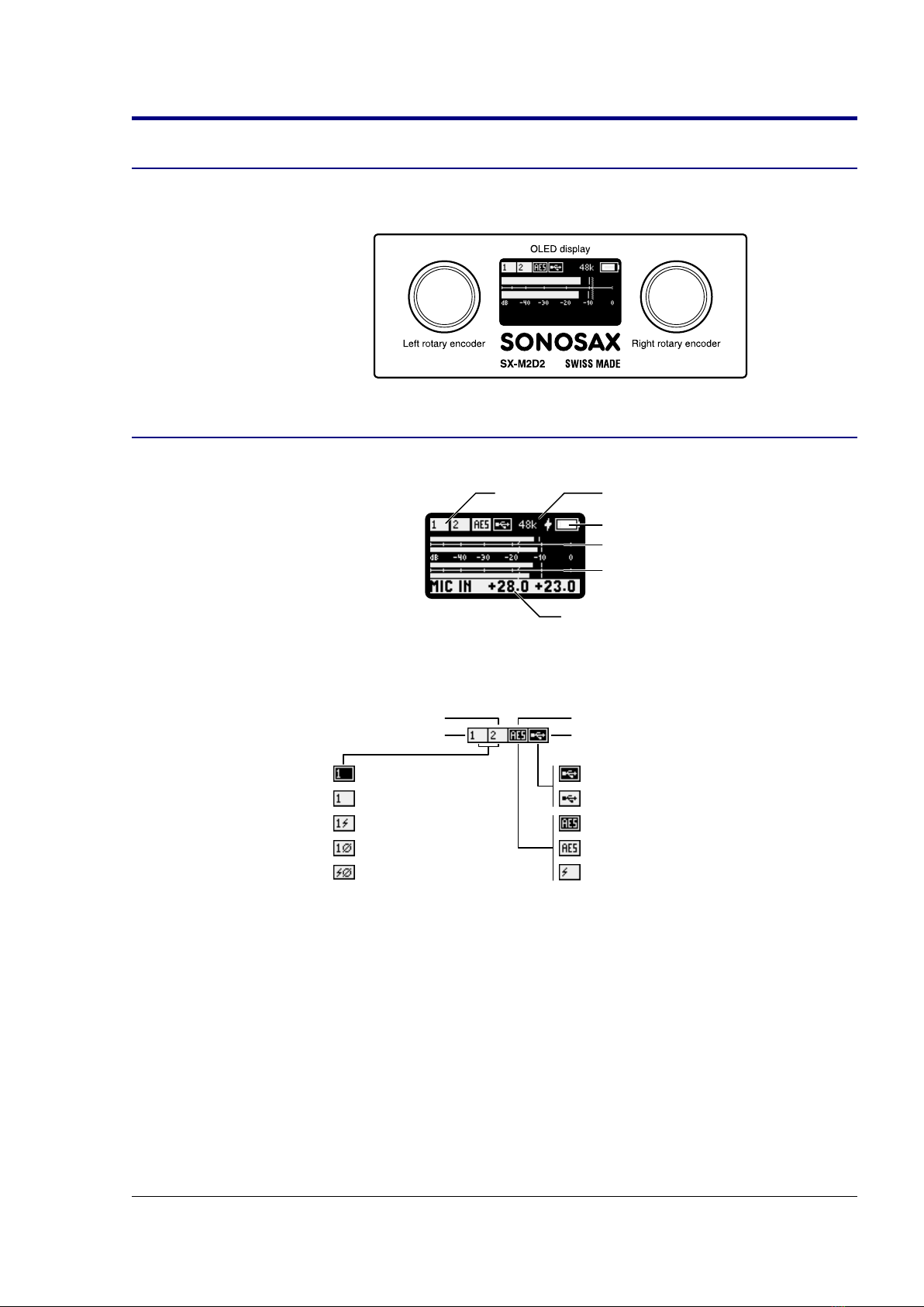
4.2 Main Screen
The main screen appears at soon as the device is booted up. It shows the following:
Inputs
Meters 1-2
Meters 3-4
Power Indicator
Sampling rate
Status bar
Upper area
The inputs status is summarized on top left of the screen.
INPUT OFF
INPUT ON
48V PHANTOM
PHASE REVERSED
48V + PHASE
MIC/LINE1
MIC/LINE2 AES IN
USB IN
AES OFF
AES3
AES42
USB DISCONNECTED
USB CONNECTED
There are 4 icons for the 4 physical inputs. A dark background means the input is OFF.
A white background means the input is powered up. Phantom power and phase
reversal are also indicated.
The system sampling frequency is always indicated at the top of the screen. The
sampling frequency can be set to 48k (factory default), 96k or 192k.
The power indicator indicates the battery status.
A bolt symbol on the left of the battery indicates an external power source is
connected. In this case, a left to right rising animated bar indicates that the battery is
currently under charge.
SX-M2D2+ User Manual 13/37

EXTERNAL POWER
ICON
IN CHARGE
ANIMATION
EMPTY BATTERY
FULLY CHARGED
TEMPERATURE CHARGE ERROR
BATTERY CHARGE ERROR
There are two errors that can occur when charging the battery:
•a thermal monitoring error
•a battery error
Meters area
The SX-M2D2 metering system offers the user the ability to observe and measure the
true peak level and to logmeasured audio levels. The metering system has the
following features:
•2 or 4 channels with user assignable source
•60dB range (see level curve below)
•user adjustable reference level
•user adjustable peak hold
•overload conditions
The following diagram summarizes the 2 and 4 channels meter screens, with peak
hold, reference level, overload and meter curve:
-60
- 0
-40
-30
-20
-10
0dB
OVERLOAD
PEAK HOLD
REFERENCE
4 CHANNELS 2 CHANNELS
LEVEL CURVE
Status bar
The bottom area default to blank, except in these conditions:
•when a rotary encoder is activated, the corresponding parameter is displayed
in this area
•when the reference tone is enabled, the tone level is displayed
Rotary Encoders
The events associated with both rotary encoders are user assignable. By default, the
left encoder modifies the Mic/Line 1 gain and the right encoder modifies the Mic/Line 2
gain.
SX-M2D2+ User Manual 14/37

Source Event
Left rotary encoder User assignable, default to Mic/Line 1 gain
Right rotary encoder User assignable, default to Mic/Line 2 gain
Left short press Enter main menu (left NAV mode)
Left long press User assignable, default to Mic/Line input menu
Right short press -do nothing- (left NAV mode)
Right long press User assignable, default to Headphones output menu
NOTE
Left and right encoder push button functions can be swapped (see
Controls Menu)
4.3 Menu Navi ation
While one of the rotary encoder is used to enter menus and select parameters
(SELECT encoder), the other one is used to exit menus and modify parameter values
(MODIFY encoder).
SELECT encoder
moves selection
MODIFY encoder
modifies the
parameter value
Navigation mode allows user to select which rotary encoder is used for these tasks.
Mode Left rotary encoder Right rotary encoder
Left NAV SELECT encoder:
•rotate: select parameter
•push: enter menu
•long push: menu back
MODIFY encoder:
•rotate: modify value
•push: exit
•long push: main screen
Right NAV MODIFY encoder:
•rotate: modify value
•push: exit
•long push: main screen
SELECT encoder:
•rotate: select parameter
•push: enter menu
•long push: menu back
The factory default NAV mode is LEFT. To change the navigation mode, see Controls
Menu.
As it is not always easy to navigate using two hands (or toggling encoders with the
same hand), a parameter can be modified by pushing the SELECT encoder while on a
highlighted parameter. Once the background color is reversed, the parameter can be
edited using the same encoder.
SELECT encoder
modifies the
parameter value
SX-M2D2+ User Manual 1 /37

4.4 Menu Tree
The following figure summarizes the SX-M2D2 menu tree:
MAIN MENU
4.5 Main Menu
The main menu allows user to select one of the 6 main sections of the menu:
SX-M2D2+ User Manual 16/37

4.6 Inputs Menu
The Inputs Menu contains settings for the three inputs of the SX-M2D2.
Each input menu has an individual configuration screen.
MIC/LINE
The Mic/Line input screen displays the two Mic/Line input configuration parameters
and peak meters.
Input Gain
PhaseLF Cut
Input Gain
+20dB
Power
48V Phantom Delay
Mic/Line 1
Mic/Line 2
The Low Frequency Cut (LF Cut) filter is disabled when it’s value is zero, otherwise
the range is 60 to 320 Hz with 20 Hz/step.
The filter response is shown below:
1 10 100 1000
-2
-20
-1
-10
-
0
No LF Cut
60
80
100
120
140
160
180
200
220
240
260
280
300
The input gain range is -24 to +72 dB, 0. dB step.
The delay range is 0 to 100ms, 1ms step at 48kHz. At 96 and 192k, the maximum
delay decreases to 0 and 2 ms. When a value is outside the range, the value blinks.
AES
The AES input screen displays the stereo AES input configuration and channel peak
meters.
SX-M2D2+ User Manual 17/37

Input Gain
Phase
AES42
Input Gain
Power
Input Frequency Delay
AES 1
AES 2
The input gain range is -24 to +24 dB, 0. dB step.
The delay range is 0 to 100ms, 1ms step at 48kHz. At 96 and 192k, the maximum
delay decreases to 0 and 2 ms. When a value is outside the range, the value blinks.
The Input Frequency displays the measured input sampling frequency.
NOTE
The AES input sampling frequency value is a measurement. The
deviation is ± 0.024%, so a 48kHz input can be displayed with a range
of ± 12Hz (47988, 48000 or 48012).
USB
The USB input screen displays the stereo USB input configuration and channel peak
meters.
Input Gain
Phase
Input Gain
Input Frequency Delay
USB 1
USB 2
The input gain range is -24 to +24 dB, 0. dB step.
The delay range is 0 to 100ms, 1ms step at 48kHz. At 96 and 192k, the maximum
delay decreases to 0 and 2 ms. When a value is outside the range, the value blinks.
The Sampling Frequency displays the measured input sampling frequency.
NOTE
The USB input sampling frequency value is a measurement. The
deviation is ± 0.024%, so a 48kHz input can be displayed with a range
of ± 12Hz (47988, 48000 or 48012).
SX-M2D2+ User Manual 18/37

4.7 Outputs Menu
The outputs menu lists all available outputs, the output setup menu and the reference
tone generator.
4.8 PHONES, LINE OUT, AES OUT, USB OUT Menus
All outputs menu screens share the same routing interface:
Stereo sources
Output level
Presets 1 to 4
Output meters
Destination routing
Output name
Source monitorin
All outputs can be the sum of 4 stereo sources:
•MIC, the two Mic/Line inputs
•AES, the stereo AES input
•USB, the stereo USB input channels
•MIX, the 2-channels internal mixer
Each of these stereo sources can be routed to the output using one of the following
pattern:
Dest.
Routing
Description Diagram
--- This source is not routed to the output
1
2
L
R
MONO Both source channels are mixed and routed to both
output channels
STEREO Each source channel is routed to the each output
channel
REV-ST Left and Right Source channels are switched
MS M / S decoding is applied between the stereo source and
the output channels
1 → L Source channel 1 is routed to left output
SX-M2D2+ User Manual 19/37

1 → C Source channel 1 is routed to both output channels
1 → R Source channel 1 is routed to right output
2 → L Source channel 2 is routed to left output
2 → C Source channel 2 is routed to both output channels
2 → R Source channel 2 is routed to right output
The following diagram summarizes how an output is processed:
2CH
2CH
2CH
2CH
MIC1
MIC2
AES2
AES1
USB1
USB2
MIX1
MIX2
REF TONE
LEFT
RIGHT
OUTPUT
LEVEL
When the reference tone is enabled, the output level is muted so that only the
reference tone is sent.
NOTE
When all source monitoring is set to ‘---’ (NONE), the output is powered
down
Output Level
The output level has a trim control with a range from -60 to +24. The output is muted
when the output level is set below -60dB.
Presets
There are 4 presets per output. They are output dependent and can be used to recall
frequently used configurations. The presets apply only on input routing, they do not
affect the output level.
A preset with a white background indicates that the preset corresponds to the current
configuration.
To recall a preset, just select it. To store a preset, apply a long press until it becomes
video reversed.
NOTE
Default presets configuration (for every output):
1. No routing (output is powered down)
2. All sources STEREO
3. All sources MONO
4. Only MIX as STEREO
SX-M2D2+ User Manual 20/37
Other manuals for SX-M2D2
1
Table of contents
Other Sonosax Recording Equipment manuals


