Sonosax SX-ST User manual

PROFESSIONNAL RECORDER
SONOSAX
SX-ST Recorder
Quick Start Guide
(Firmware revision 4.2)
audio equipment manufacturer
SONOSAX SAS S.A.
Ch. de la Naz 38
1052 Le Mont s/Lausanne
SUISSE
Tel: +41 21 651 0101
Fax: +41 21 651 0109
Web: www.sonosax.ch
May 2012

SONOSAX SX-ST RECORDER Quick Start Guide Page 2 of 26
TABLE OF CONTENT
1. DIGITAL MODULE: A/D CONVERTER & INTERNAL 8 TRACKS RECORDER .............................................. 3
1.1 A/D CONVERTER................................................................................................................................................ 4
1.1.1 Source selector [IN 1 MIX] to [IN 8 MIX]............................................................................................................... 4
1.1.2 Red led indicator [ L/O ]........................................................................................................................................ 4
1.1.3 Protection Limiter's [ LIMITERS ].......................................................................................................................... 4
1.1.4 Sampling frequencies ........................................................................................................................................... 4
1.1.5 Clocking and Sync................................................................................................................................................ 5
2. INTERNAL RECORDER...................................................................................................................................... 6
2.1 CONNECTIONS ................................................................................................................................................... 6
2.1.1 Port USB 2.0......................................................................................................................................................... 6
2.1.2 Remote Connector [ REMOTE ] ........................................................................................................................... 6
2.1.3 Time Code Connector [ TC ]................................................................................................................................. 6
2.1.4 Sync Connector [ VIDEO IN ] ............................................................................................................................... 6
3. OPERATING INSTRUCTIONS ............................................................................................................................ 7
3.1 RECORDER CONTROLS AND STATUS ............................................................................................................ 7
3.1.1 Recorder's function keys ...................................................................................................................................... 7
3.1.2 Recorder's status.................................................................................................................................................. 7
3.2 MAIN DISPLAYS ................................................................................................................................................. 9
3.3 INPUT CHANNELS VS RECORDER TRACKS................................................................................................... 9
3.4 INPUTS MODULOMETERS................................................................................................................................. 9
3.5 TRACKS MODULOMETERS............................................................................................................................. 10
3.6 MAIN MENU....................................................................................................................................................... 11
3.7 HEADPHONES MONITORING CONFIGURATION........................................................................................... 11
3.7.1 SOLO MONITORING MODE.............................................................................................................................. 12
3.8 TAG LAST TAKE............................................................................................................................................... 13
3.9 METADATA ....................................................................................................................................................... 14
3.9.1 PLAYER mode: .................................................................................................................................................. 15
3.10 BROWSE FILES MENUS .................................................................................................................................. 16
3.11 LAST TAKES MENU ......................................................................................................................................... 17
3.12 PLAYER MODE ................................................................................................................................................. 17
4. SETUP MENU .................................................................................................................................................... 18
4.1 CONFIGURING THE RECORDER .................................................................................................................... 18
4.1.1 Configuring the Tracks [REC TRACKS].............................................................................................................. 18
4.1.2 Track Routing ..................................................................................................................................................... 19
4.1.3 Track Naming ..................................................................................................................................................... 20
4.1.4 Example of a complete configuration.................................................................................................................. 20
4.1.5 Mirroring ............................................................................................................................................................. 20
4.1.6 Recording parameters [REC SETUP]................................................................................................................. 21
4.2 TIMECODE SETUP............................................................................................................................................ 22
4.3 USER SETTINGS............................................................................................................................................... 23
4.4 SYSTEM SETUP................................................................................................................................................ 24
5. ADDENDUM....................................................................................................................................................... 26

SONOSAX SX-ST RECORDER Quick Start Guide Page 3 of 26
1. DIGITAL MODULE: A/D CONVERTER & INTERNAL 8 TRACKS RECORDER

SONOSAX SX-ST RECORDER Quick Start Guide Page 4 of 26
1.1 A/D CONVERTER
The 8 ways high quality Analogue to Digital converter is located on the upper half of the Digital module. Its
sampling frequencies range from 44,1kHz up to 192 kHz with a resolution of 24bits. The overall dynamic
range reaches 120dB.
Each channel is equipped with a Limiter to protect the converter against eventual "clipping".
The 8 digital channels – 4x AES/EBU pairs – are available on the 25 pin Sub-D connector [DIGITAL I/O] on
the rear panel of the mixing console. These four digital outputs are transformer balanced and comply with the
AES31 standard. The configuration of these digital outputs is:
AES 1 = channels 1 & 2 AES 2 = channels 3 & 4
AES 3 = channels 5 & 6 AES 4 = channels 7 & 8
Please refer to the addendum for the wiring diagram of the 25 pin Sub-D connector.
1.1.1 Source selector [IN 1 MIX] to [IN 8 MIX]
The eight A/D Converters receive either the direct output of the first 8 input channels or the 8 master outputs
of the Groups 1 to 8. The switches [IN 1 MIX] to [IN 8 MIX] individually select for each digital channel which of
the source is sent to the corresponding A/D converter:
- Position [IN]: the direct output of the corresponding Input module is sent to the A/D Converter. It is
the same modulation as outputted at the [LINE OUT 1-8] connector. Thus, it depends
on the internal selection Pre EQ – Post EQ – Post Fader.
- Position [MIX]: the modulation of the corresponding Group is sent of the A/D Converter.
- Centre Position: The A/D Converter is powered off, thus reducing the overall power consumption of the
console. The A/D Converters are always powered per pair; therefore both switches of
the same pair must be in centre position to power off the converter.
Please note that powering the ADC on or off generates an audible noise.
1.1.2 Red led indicator [ L/O ]
The red Led [L/O] located above each source selector lights on either to indicate the Limiter activity [L] (when
the modulation reaches the Threshold of the limiter) or when the modulation reaches the clipping level at
0dBFS [O] (O= overflow).
NOTE: as soon as one of the channel of an ADC reaches the clipping level, both leds will light On to
indicate the Overflow
1.1.3 Protection Limiter's [ LIMITERS ]
Each of the eight channels of the digital module is equipped with an individual limiter to prevent the ADCs from
eventual clipping (or overflow). To provide with an efficient protection, the Limiters have a very fast attack time
of half a period.
The [LIMITERS] switch engages or disengages the eight limiters simultaneously.
The Limiter's Threshold is factory set at -3dBFS; its "compression" ratio is approx 15:1
1.1.4 Sampling frequencies
The A/D Converters have a fixed resolution of 24bits; the sampling frequencies stage from 44,1 up to 192kHz,
and is determined by two switches:
- The upper switch selects one of the two fundamentals frequencies; 44,1KHz or 48KHz
- The lower switch selects a multiple of these fundamentals: 44,1 – 88,2 – 176kHz or 48 – 96 – 192kHz
NOTE: The 0.1% Pull Up / Pull Down functionality, commonly used in NTSC domain, is only possible
when the internal recorder is installed.

SONOSAX SX-ST RECORDER Quick Start Guide Page 5 of 26
1.1.5 Clocking and Sync
The A/D Converters are synchronized by an internal clock having accuracy better than ± 2ppm. When the
Digital module is installed, the same clock is used to synchronize the internal DC/DC converter powering the
entire mixer, thus avoiding phasing problem or digital noises.
Synchronizing the ADC trough an external clock – such as a video burst or a wordclock – is only possible
when the Internal Recorder is installed. If the Digital module holds the A/D converter only - without Recorder –
the A/D Converter will only lock on its internal clock; thus the ADC will be working as "Master".
A wordclock output is available on the Lemo 5 pin connector to synchronize external equipments such as an
external recorder.
The mating cable connector is a Lemo 5pin, SONOSAX Reference nr: SX860232
Lemo Reference nr: FGG.0B.305.CLAG52
Pin 1 = GND / Pin 2 = T.C. IN / Pin 3 = n.c. / Pin 4 = WordClock Out / Pin 5 = T.C. OUT

SONOSAX SX-ST RECORDER Quick Start Guide Page 6 of 26
2. INTERNAL RECORDER
The internal 8 tracks recorder occupies the lower half of the digital module. It includes a keypad with three
push buttons, a compartment for the hard disk, a slot for a CF card, a USB 2.0 port and a wired remote
control.
The recorder works in conjunction with the 8 channels A/D converter located just above. It can record up to 8
tracks on the hard disk - or on a SSD drive as an option - and up to two independent tracks on the
CompactFlash card. The CF card can also operate in Mirroring mode, so that it records simultaneously the
exact copy of what is recorded on the hard disk.
The WAV files are uncompressed, PCM encoded in 24 or 16 bit and contain a double implementation of BWF
and iXML meta data's.
NOTE:To avoid loss of files during recording, the recorder continuously monitors the [Power Off]
switch of the console. It prevents turning off the console if a recording is in progress or as long
as the recorder still "writing" on the hard disk.
2.1 CONNECTIONS
A USB port is available on the front panel for files transfer to a computer and a set of connectors on the rear
panel provides connections for the remote control, clock synchronization and time code.
2.1.1 Port USB 2.0
This connector on the front panel is a USB 2.0 only and is not compatible with older USB 1.0 standard.
It allows connection to any computer having a USB 2.0 port (PC or MAC). Once it is connected to a computer,
the hard drive and / or card the ComapctFash appear on the desktop as an external media.
WARNING:when connecting to a computer, it is imperative to use a certified cable "USB 2 High Speed".
The speed of data transmission is such that the use of cable not certified "High Speed" may
cause malfunctions (disk not recognized or not appearing on the desktop - Windows error
Code 10, etc.)
2.1.2 Remote Connector [ REMOTE ]
This connector is used only for connecting the dedicated remote and can not be used for other purposes. The
wired remote is included with the recorder. It is used to configure all the parameters of the recorder and to
display the modulation levels of the 8 tracks of hard disk and the 2 tracks of the CF Card.
2.1.3 Time Code Connector [ TC ]
This 5 pin Lemo connector can either receive an external Time Code, or to provide a time code output in all
common formats, including the frame rate at 23.976. This connector also provides with the WordClock Out of
the A/D converter. The pin out matches with the Aaton standard
The mating cable connector is a Lemo 5pin
SONOSAX Reference nr: SX860232
Lemo Reference nr: FGG.0B.305.CLAG52
Pin 1 = GND / Pin 2 = T.C. IN / Pin 3 = n.c. / Pin 4 = WordClock Out / Pin 5 = T.C. OUT
2.1.4 Sync Connector [ VIDEO IN ]
The SMA connector allows connection of either a video sync signal or an external WordClock. A detailed
explanation follows in the chapter [SYNC IN].
An SMA to BNC adapter is available under reference SX 860620

SONOSAX SX-ST RECORDER Quick Start Guide Page 7 of 26
3. OPERATING INSTRUCTIONS
3.1 RECORDER CONTROLS AND STATUS
The recorder is controlled mainly by the 3 function keys on the recorder module; the touch screen of the
remote control is used for configuration and settings purposes as well as metadata editing.
3.1.1 Recorder's function keys
- Record Ready mode, the key is flashing; pressing briefly starts recording
RECORD KEY - While recording, the key lights steady; pressing briefly adds an Index**
- While recording, a long pressure stops recording
- In record ready mode, pressing the PLAY key open the LAST TAKE
PLAY KEY menu on the remote, select a Take and press PLAY again to start playing
- While Playing, press briefly to PAUSE at current location, the key flashes;
a long pressure while playing or in pause will STOP, the key is darkened.
MONITOR KEY - Act as any other P/A key on the mixing console, pressing the P/A key
toggles between the monitoring of the console and the monitoring of the
recorder's tracks, as selected in the HEADPHONES menu
** INDEX = New TAKE: pressing the REC key briefly while recording will automatically create a new TAKE
the Take number is automatically incremented by 1.
NOTE: the RECORD key can be pressed in any situation to immediately start recording (Scratch
Record), even while playing a Take; obviously there is no pre-record in this case.
3.1.2 Recorder's status
The status of the recorder is always posted on the upper left corner of the screen on the remote control,
regardless of the displayed menu:
Red dot Flashing: Record Ready
Red dot Steady: Recording in progress, the lower region of the screen toggles from blue to red
and a second red dot is posted on the upper area of the screen
Green triangle Steady: Playing a take
Green double bars: Player in Pause
Green square flashing: Player in Stop
P/A
SONOSAX SX-ST RECORDER Quick Start Guide Page 8 of 26
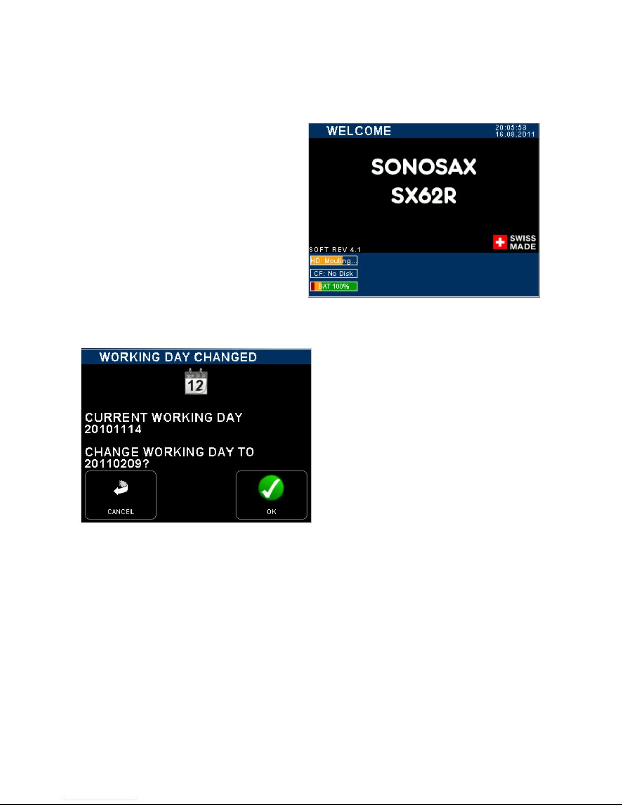
When turning On the SONOSAX SX-ST mixing console a boot-up screen is posted on the display of the
Remote Control as illustrated below.
If the working day has changed while powering
up the unit, the system asks to confirm the date
of the new working day. This allows keeping the
date of the current working days if the on going
production works is passing across midnight.
Press [OK] to confirm the new working day
Press [CANCEL] to keep the current working day
When one of the key is pressed, the unit will
continue the booting procedure; wait a few
seconds until the main screen appears
SONOSAX SX-ST RECORDER Quick Start Guide Page 9 of 26
3.2 MAIN DISPLAYS
3.3 INPUT CHANNELS VS RECORDER TRACKS
When the booting procedure is completed, the main screen displays the modulometers of the inputs channels
as well as main information's related to the set up of the recorder.
The main screen displays either the modulometers of the audio channels at the inputs or the recorder (which
means the audio outputted by the A/D Converters) or the modulometers of the recorder's tracks (see
examples below). Touching the blue region at the bottom of the screen toggles the metering of the Inputs
channels or the metering of the recorder's Tracks.
For sake of clarity in reading this manual, please note that:
- Inputs or channels: always refer to a physical input or output of the analogue mixer or of the A/D Converter
- In the next chapters, the word "Input" always refers to the digital audio applied at the input of the recorder
- Tracks: always refer to a virtual track of the recorder
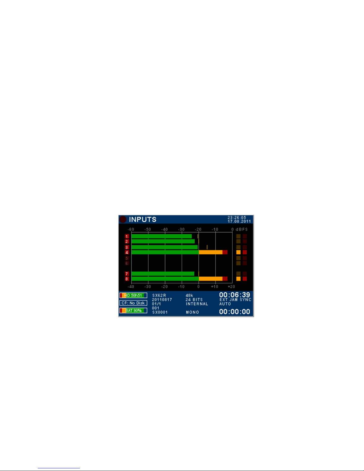
3.4 INPUTS MODULOMETERS
When the screen shows the INPUTS modulometers, numbers 1 to 8 represent the digital audio applied at the
input of the recorder; this means the audio channels fed from the output of the A/D Converter. Obviously the
audio depends on selected source the A/D Converter (either the direct out of the channels or main Mix buses)
- On the first column, the numbering from 1 to 8 represents the number of the input channels
- High-lighted Red square indicates that an input channel is assigned on an armed track, ready to record
- A dimmed Red square means that no input is assigned and/or the track is not armed.
Input channels modulometers System Date & Time
Digital scale in dBFs
High lighted Red squares on
input channels 1 to 4 = the
inputs are routed on armed
tracks
5 & 6 are dimmed = input
channels are not routed or the
tracks are not armed
Red Dot = Overload
Inputs 7 & 8 are routed on
armed tracks
Digital scale below the
designed reference level
Remaining capacity on HD Time Code value
Remaining capacity on CF Time Code Synchronisation
Battery or external level indicator
(in volts) Elapsed time
STREC =
20110817=
01/1 =
001 =
SX0001 =
Project name
Working Day
Scene name
Take number
Filetag
Sampling Frequency
Resolution (Bits per sample)
Audio Sync mode
Audio File format
SONOSAX SX-ST RECORDER Quick Start Guide Page 10 of 26
Another example of configuration
Inputs modulometers
1 to 6 are dimmed = input channels are not routed or
tracks are not armed (will not be recorded)
7 & 8 brightened = channels 7 & 8 routed on armed
tracks (will be recorded)
TOUCH THE LOWER REGION TO TOGGLE THE
METERING OF RECORDER'S TRACKS
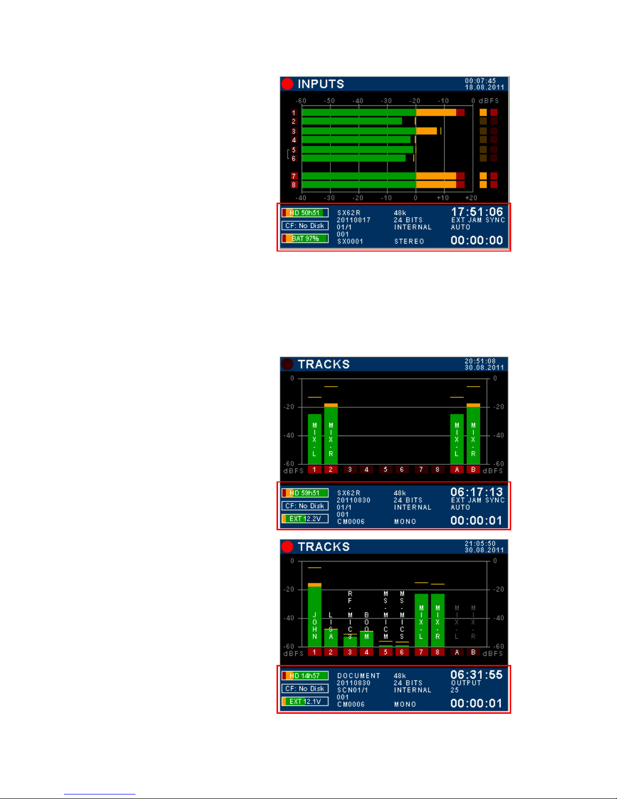
3.5 TRACKS MODULOMETERS
Multiple inputs can be routed (mixed) on the same track; thus when the screen displays the modulometers of
the recorder's TRACKS, each track represents the sum of all assigned inputs on that particular track, in other
words it shows what is effectively recorded on the tracks.
If the Inputs are not assigned on a 1:1 routing, toggling the metering allows a rapid comparison between the
modulation level of the channels and the modulation level of the recorded tracks.
Recorder's Track modulometers
Input 7 & 8 used as main Mix-L & Mix-R are assigned
on tracks 1 & 2 on the H.D. and on tracks A & B on the
CF Card
TOUCH THE LOWER REGION TO TOGGLE THE
METERING OF INPUT CHANNELS
Recorder Track modulometers
Typical 1:1 assignment of input channels onto recorder's
track. In this example, tracks A & B of the CF Card are
not assigned and not armed
TOUCH THE LOWER REGION TO DISPLAY THE
METERING OF THE INPUT CHANNELS

SONOSAX SX-ST RECORDER Quick Start Guide Page 11 of 26
3.6 MAIN MENU
Pressing the main screen anywhere above the blue area will call the Main Set Up Menu. Pressing any key will
call a Sub-Menu
<= Indicated the status of the recorder
[TAG LAST TAKE] tag as False start, Wild track,
No good or Circled
[METADATA] edit the Metadatas
[HEADPHONE] configure the Headphones
outputs
[BROWSE FILES] browse recorded takes in the
HD or CF card
[BACK] return to the main screen
[SETUP] configure all parameters of the recorder
[LAST TAKES] displays the last recorded takes
3.7 HEADPHONES MONITORING CONFIGURATION
When the [P/A] key is activated, the monitoring selection on the mixing console is overwritten as with any
other P/A key (PFL); then the modulation sent to the [PHONES] outputs corresponds to the selection of the
recorder's tracks as set in this [HEADPHONES] menu.
The tracks can be configured either as stereo pairs, or individually as a mono track. Tracks 1 to 8 are the
tracks on the Hard disk, A & B are the two tracks of the CF Card
- A primary "switch" toggles the different monitoring modes for pairs 1-2, 3-4 or 5-6: OFF – MONO – STEREO
– REVERSE STEREO – MS – OFF.
- Two secondary "switches" freely assigns each tracks of the pair to the Left or Right channel of the secondary
monitor output: OFF (–) ; Left [L] ; Right [R] ; Centre [C] (equal volume on Left and Right); when the tracks are
individually assigned the primary switch posts "USER".
- The first column of switched toggles the secondary monitoring to SOLO MONITORING mode.
The first row toggle the
SOLO MONITORING
Primary switches select the
monitoring mode per pair:
OFF, MONO, STEREO, REV-
ST , MS or indicates USER
Odd track of the pair
Secondary switches route each
track individually:
OFF – L – R – C
Even track of the pair
Return to previous Menu 4 preset keys to store and
recall user's selections **
** Press 2 seconds on a preset key to store the configuration as it appears on screen
NOTE: any other position than [REC] on the primary selector monitors the analogue section of the mixer
SONOSAX SX-ST RECORDER Quick Start Guide Page 12 of 26
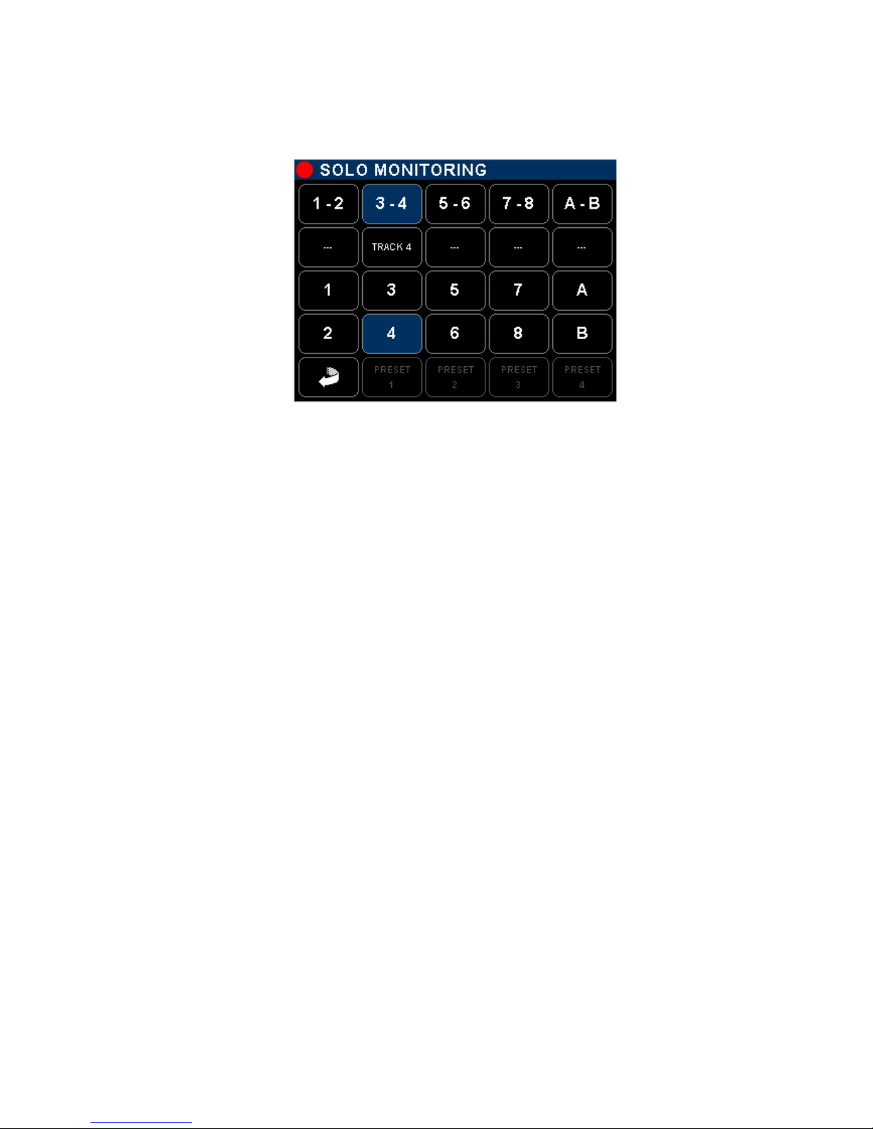
3.7.1 SOLO MONITORING MODE
Touching a key in the first row on the HEADPHONES page activates the SOLO MONITORING mode; use this
page to temporarily listen in SOLO mode any individual track, or pair(s) of track(s) or any combination.
Enable / disable the pair,
It's monitoring mode is as
configured in the
HEADPHONES page ( Non
exclusive selection ) Second row:
Enable / disable the pair and
toggles its listening mode:
Odd– Even– Stereo – MS –
OFF
( Non exclusive selection )
3rd and 4th row:
Select each track individually in
exclusive mode, all other tracks
are muted
Return to HEADPHONES
Output page, the monitoring is
resettled in its original
configuration
No Preset in Solo Monitoring
mode
¨
SONOSAX SX-ST RECORDER Quick Start Guide Page 13 of 26
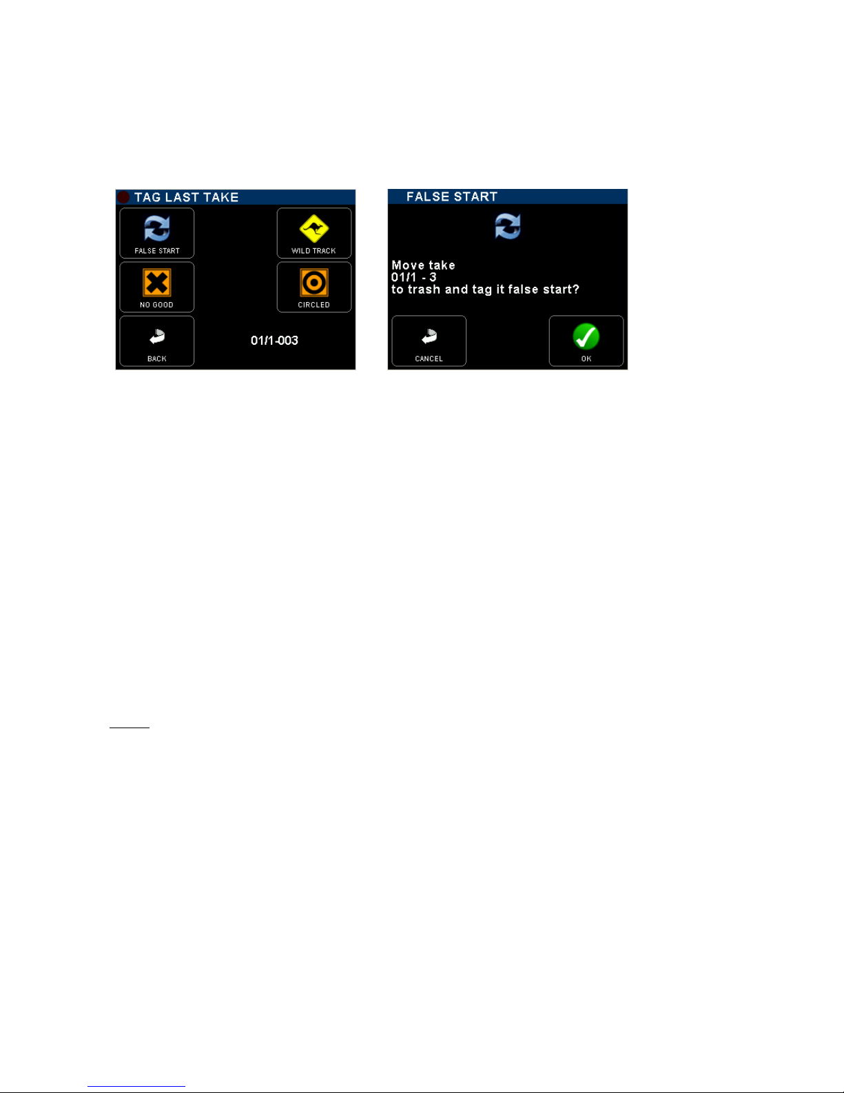
3.8 TAG LAST TAKE
This menu offers a quick access to tag the last recorder take either as False Start or to mark the audio file by
editing its Metadata. From the main contextual menu enter the [TAG LAST TAKE] sub-menu then choose one
of the following option; a message will be posted, asking to confirm; select [OK] to confirm or [CANCEL] to
resume and return to the previous menu.
•FALSE START Tag the last recorded take as "False Start" and move the audio files to the
[TRASH] bin. The Take nr will be decremented by one so that the next take will
by tagged with the correct Take Nr. The audio file is notified with the suffix "F"
when browsing the [TRASH] directory.
•WILD TRACK Tag the metadata of the last recorded take as "Wild Track" to notify the post
production that the audio file are not related or not "In Sync" to a specific video
take, usually used for ambiances or atmo's.
The audio file is notified with the suffix "W" in the [BROWSE FILE] menu.
•NO GOOD Tag the metadata of the last recorded take as "No Good", mostly used to warn
the post-production that the recorded audio is to be rejected although the video
take having the same take nr might be good.
The audio files remain in the current working day directory, the Take nr is kept
and the audio file is notified with the suffix "F" in the [BROWSE FILE] menu.
•CIRCLED Tag the metadata of the last recorded take as "Circled" to notify the post
production that the recorded audio files are to be choosen although the video
take having the same take nr might be rejected.
The audio files remain in the current working day directory, the take nr is kept
and the audio file is notified with the suffix "C" in the [BROWSE FILE] menu
NOTE: The screen displays the [SCENE NAME] and the [TAKE NR] of the selected audio file.
If no file is available the screen posts [NO TAKE AVAILABLE]
SONOSAX SX-ST RECORDER Quick Start Guide Page 14 of 26
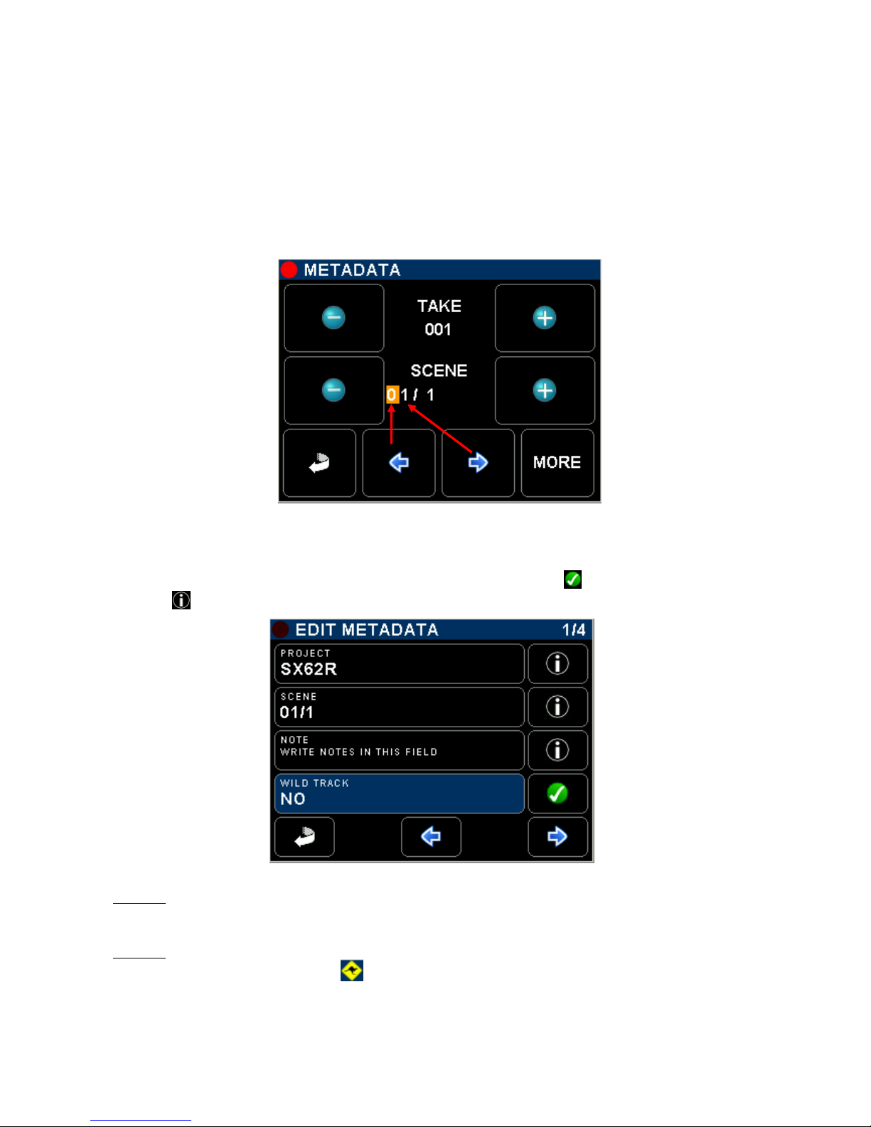
3.9 METADATA
The recorded audio files embeds metadata in both BWF and iXML format. Some metadata can be either pre-
settled when in Recorder Ready mode or edited post-recording when the unit is in Player mode.
Editing metadatas is not possible while recording.
Editing the metadata is spread over several pages; available metadata fields depend on the operating mode.
The first page shows two editable fields: the [SCENE] name which can contain up to 8 characters and the
[TAKE NR] which is fixed to 3 numerical digits. As soon as the Scene name is changed, the TAKE nr is reset
to 001. When typing a Scene name that already exits, the TAKE nr is automatically set to the next available
value in the Working Day folder for that particular Scene name.
Decrement TAKE Nr by 1
Keep pressing to scroll
Down rapidly
Increment TAKE Nr by 1
Keep pressing to scroll Up
rapidly
Decrement the selected
character value by 1,
Numerical or alphabetical.
Keep pressing to scroll Up
rapidly
Increment the selected
character value by 1,
Numerical or alphabetical.
Keep pressing to scroll Up
rapidly
Return to Main Menu
Call the next page for more
metadatas
Move the cursor to the Left Move the cursor to the Right
The fields displayed in the second page depend on the operating mode; the selected field is high lighted in
blue. Depending on its content, selecting a field either call a keyboard to edit a text or toggle between the
possible filetags. Once set, confirm the selection with the green "check" key
Pressing displays additional information about the selected field
Menu's page count
Edit the PROJECT name
Press to call a keyboard
Press to get additional
information's
Edit the SCENE name
Press to call a keyboard
Press to call a keyboard
and write notes
Tag the audio file as Wild
Track,
Confirm selection with the
green check key
Return to first Metadata
page
Call the next page for
more metadatas
Call the previous page
NOTE 1: Setting a new Project name will create a new directory at the root level of the hard disk and
of the CF Card, all subsequently recorded files are then stored in the "working day's"
subdirectory(ies) that belong to that particular project.
NOTE 2: when "Wild Track is enabled, all subsequently recorded files will be tagged as "Wild
Track"; the symbol is posted on the main modulometger's screens warning the user
that the wild track tag is enabled. Recorded audio files are notified with the suffix "W" in the
[BROWSE FILE] menu.
SONOSAX SX-ST RECORDER Quick Start Guide Page 15 of 26
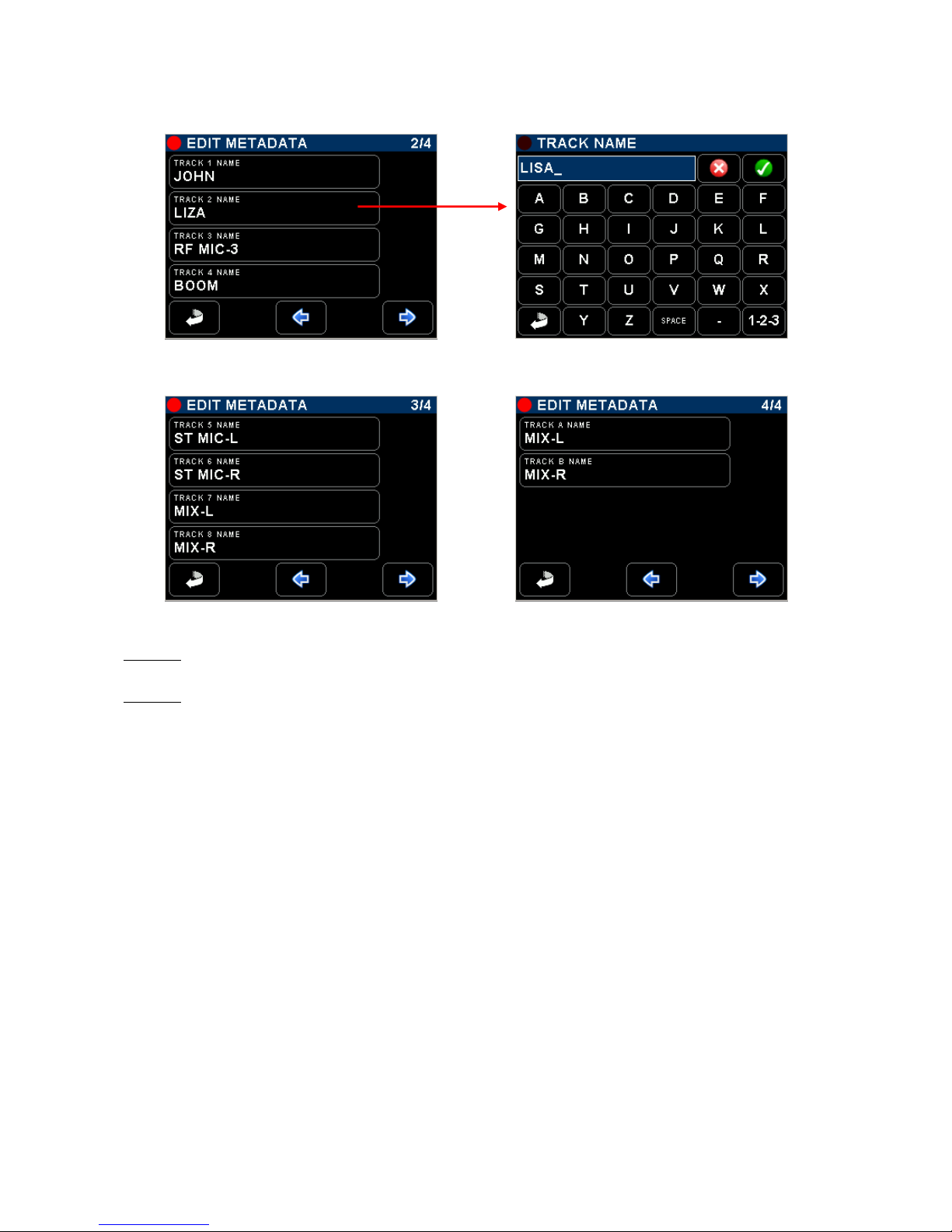
In Recorder operating mode, the pages 2 to 4 are used to edit the track name to be recorded on the hard disk
and on the CF card; these names are stored in the metadata of audio files
Edit names of tracks 1 to 4 Press on a track to call the Keyboard
Edit names of tracks 5 to 8 Edit names of tracks A & B on CF Card
NOTE 1: When the CF Card is set to MIRRORING mode, all track names set on the HD are
replicated on the CF Card.
NOTE 2: In Player mode, only the recorded tracks can be edited, non recorded track do not appear
in the list.
3.9.1 PLAYER mode:
editing the metadata of a recorded audio file implies that the take is loaded in the Player.
•PROJECT in player mode, editing the [Project] name of an existing audio file will only modify the
content of the metadata but does not create a new directory.
•SCENE: editing the [Scene] name of an existing audio file only modify the metadata of that
particular field but does not reset or modify the Take number.
•TAPE: this field corresponds to the "Tape Roll". It is always set to "Working Day" value.
•WILD TRACK Tag the recorded file as "Wild Track"; when loaded in the player a symbol is posted in
the [Track Monitoring] page. Wild Track audio files are notified with the suffix "W" in
the [BROWSE FILE] menu.
•CIRCLED Tag the recorded file as "Circled", the audio file is notified with the suffix "C" in the
[BROWSE FILE] menu
•NO GOOD Tag the recorded file as "No Good", the audio file remains in its original folder and is
notified with the suffix "F" in the [BROWSE FILE] menu.
•FALSE START Unlike editing the file from the [TAG LAST TAKE] menu, tagging the audio file from the
Player only edits the metadata but does not move audio files to the [TRASH] bin and
does not modify the Take Nr.
The audio file is notified with the suffix "F" in the [BROWSE FILE] menu.

SONOSAX SX-ST RECORDER Quick Start Guide Page 16 of 26
3.10 BROWSE FILES MENUS
The file browser is used to search the takes stored on the hard disk or on the CF card. Selecting the media
[HD] or [CF] is done at the upper level of the the browser. Select a media to reaches the root level of that
media or select the [BACK] icon to return to the Main Menu.
Main Menu Media Selection Project Folders Working Day's
The root level of the media lists all the [PROJECT] directories sorted in alphabetic order, including the
[TRASH] bin. The root level of the hard disk drive also contains the "user settings" directories [SETTINGS];
user settings can be loaded directly from this folder.
Selected Media HD or CF
Project Folder Scroll Up 10 lines at a time
User settings Folder Scroll Up 1 lines at a time
Project Folder Scroll Down 1 lines at a time
Trash bin Scroll Down 10 lines at a time
Return to Main Menu
Back to an
upper level
Move the selected
Folder to Trash bin
Scroll Up or Down then touch on the name to select a [PROJECT], a new screen lists the related [WORKING
DAY] folders - sorted in chronological order – which contains the recorded takes.
[BACK] returns to the main menu
[FOLDER] icon steps back to an upper level of the tree stucture
[DELETE] moves the selected folder to the trash bin, a message is posted asking to confirm deletion;
first touch on "delete" key then select the folder to delete
Media /Project /Working day
The [WORKING DAY] folders lists all recorded takes sorted by their [FILETAG] (unique identifier). The takes
are identified by their [SCENE] name and [TAKE] number.
Scroll Up or Down to choose then select a take to load it in the player.
When a take is selected, the recorder automatically switches to PLAYER operating mode and reconfigure
itself with the same parameters as set during the recording of that take.
SONOSAX SX-ST RECORDER Quick Start Guide Page 17 of 26
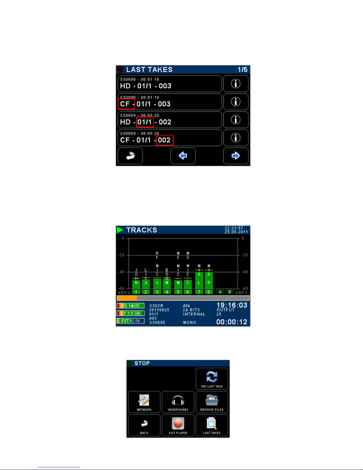
3.11 LAST TAKES MENU
The [LAST TAKES] page provides quick access to the last recorded takes, displayed in reverse order; the last
recorded take being displayed on the top of the list.
- SX0090 = FILETAG
- Take duration
- Media on which the take is
stored
- Scene name
- Take number
Display information related
to the recorded take:
- Drive: HD or CF
- Scene name
- Take number
- Tracks count
- Creation date and time
- Duration
- Time Code at start
Return to Main menu
Next / Previous pages
3.12 PLAYER MODE
When a TAKE is loaded either from the [LAST TAKE] menu or from the [BROWSE FILE] menu, the recorder
will switch to PLAYER mode and will automatically reconfigure the system with the same parameters as set
during the recording of that particular Take; Routing - Monitoring - etc.
In Player mode, the screen displays only the modulometers of the [TRACKS]. The modulometer screen is very
similar as when in Recorder mode, but shows a progression bar under the modulometers
Play mode System Date and Time
Progression bar
- Time Code value
- Time code format
- Elapsed Time
The progression bar represents a "Time Line", while in PLAY or in PAUSE touch anywhere within the
progression bar to jump to another location on the time line.
The main menu in Player mode slightly differs from the main menu while in Record mode.
Press [EXIT PLAYER] to return in Record operating mode
SONOSAX SX-ST RECORDER Quick Start Guide Page 18 of 26
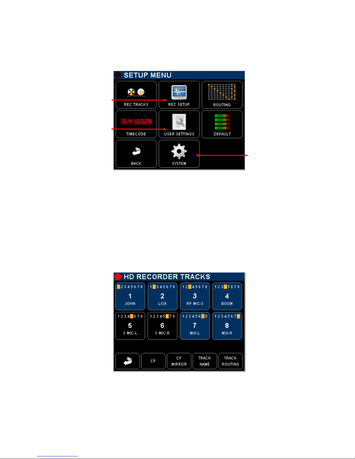
4. SETUP MENU
The [SETUP MENU] gives access to several Sub pages to configure the Recorder such as track arming and
routing and all recorders' setup, to the Time Code settings, to store and recall user's settings, to setup
system's parameters off the recorder.
Track configuration: arming,
routing, naming
Recorder set-up: sampling,
bit depth, file format, sync
mode, pre-record etc
Call a cross matrix in X-Y
format for track routing.
The logo displays the
current configuration
Set up all Time Code
parameters
Store and Recall Users
Settings
Toggle Backlight mode:
Default = normal
Reversed = direct sun light
Return to Main Menu
Call the System Setup
All keys call specific sub-menus except the "Backlight Key" that toggles the backlight of the Inputs or Track
Monitoring pages as follow:
- DEFAULT: modulometers are displayed over a black background
- REVERSED: modulometers are displayed over a white background with a higher contrast to improve
reading on direct sun light
4.1 CONFIGURING THE RECORDER
4.1.1 Configuring the Tracks [REC TRACKS]
Assigning input channels to the tracks, arming and naming tracks on the Hard disk and CF Card is done in
this menu; the same routing is replicated in an X-Y cross matrix form in the [ROUTING] page; both forms are
provided so users can choose.
Touch a Track key to arm /
unarm a track.
Armed track in blue (will be
recorded)
Unarmed track in black (will
not be recorded)
Return to previous menu
Assigned Input channel are
highlighted in yellow over
track keys;
the displayed example
shows a 1 x 1 assignment:
Input channel 1 on track 1
Input channel 2 on track 2
etc
TRACK ARMING: toggle to arm / un-arm a track, armed track are notified with a highlighted red square on
the main Track Monitoring screen.
CF: call the CF Card configuration page
CF MIRROR: toggle the mirroring; (mirroring = CF replicates the HD)
TRACK NAME: edit track's name
TRACK ROUTING: edit the input channels assignment to recorder's tracks

SONOSAX SX-ST RECORDER Quick Start Guide Page 19 of 26
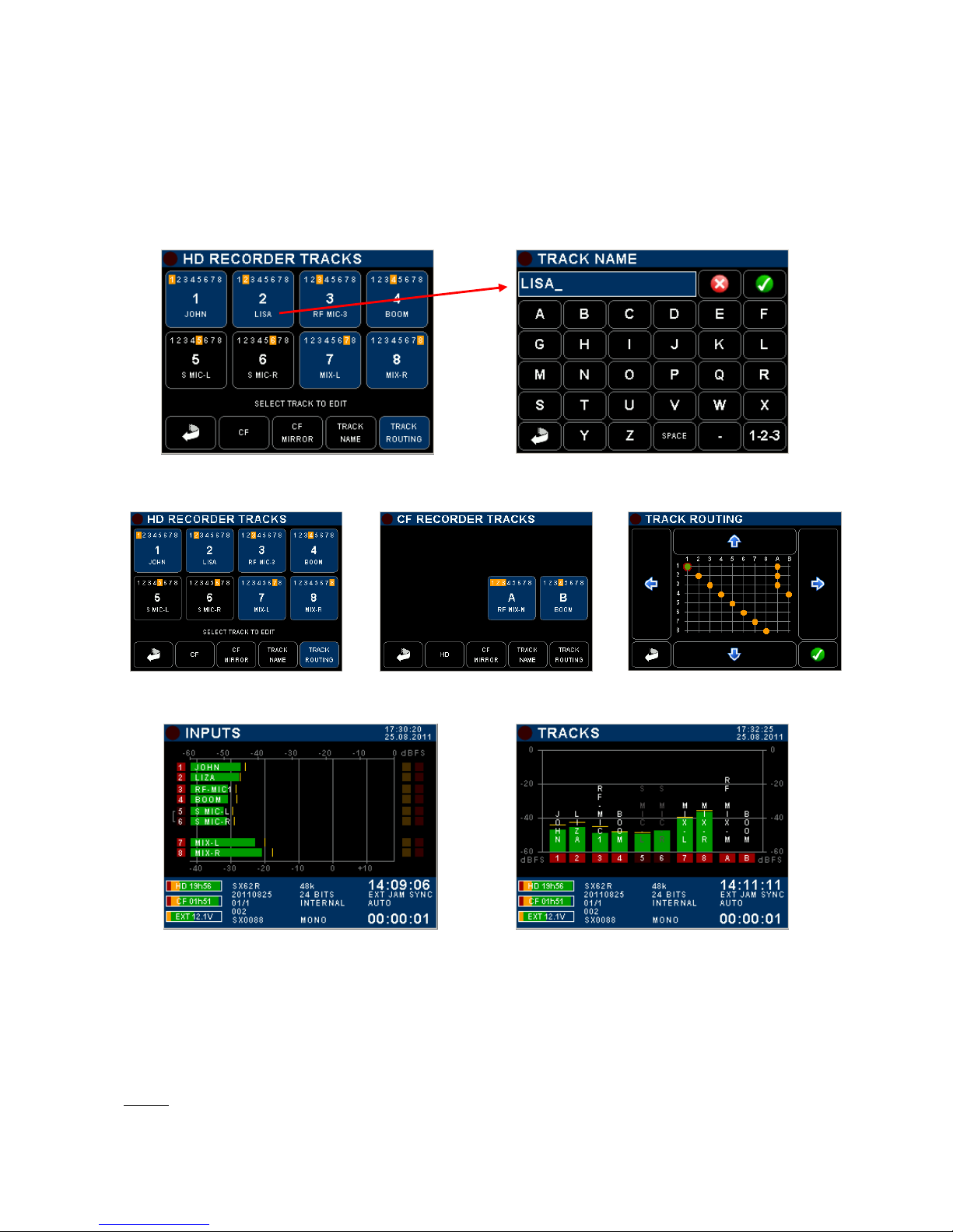
4.1.2 Track Routing
Assigning the input channels on the recorder's track is done pressing the [TRACK ROUTING] key – all track
keys will flash - and then by selecting the track number; a new page is displayed to choose which input
channel(s) will be assigned on the track. Toggle the input channel number assign/un-assign the channel.
Multiple input channels can be assigned to the same track (mixing)
Select Previous track
Select Next track
The [ROUTING] menu performs the same operation, but through a more intuitive X-Y matrix; the A & B tracks
represent the two tracks on the CF Card, providing the Mirroring is not enabled.
Move the cursor with the Up / Down / Left / Right arrows and then assign / un-assign with the "check" key
=
H.D. Tracks
1 to 8
In
p
ut Channels 1 to 8
CF Tracks
A & B
SONOSAX SX-ST RECORDER Quick Start Guide Page 20 of 26
4.1.3 Track Naming
Naming a track on the hard disk or on the CF Card is done by pressing the [TRACK NAME] key - all keys
flashing - then by selecting the track number; a keyboard is displayed to type the name (max 8 characters ).
The name belongs to the track (not to the input channel) and is embedded in the metadata of the audio file.
Track names are displayed over the modulometer on the [TRACKS] monitoring screen; the name is replicated
over the modulometer of the corresponding input channel on the [INPUTS] monitoring screen, providing that
inputs are routed on a 1:1 configuration.
4.1.4 Example of a complete configuration
+ =
Tracks 5 & 6 are routed but not armed Input channels 1, 2 & 3 assigned and mixed to track A on CF Card
1 x 1 assignment on the HD Tracks Input channels 4 assigned to track B on CF Card
4.1.5 Mirroring
When CF MIRROR function is enabled, the CF card replicates the same routing as set for the HD. The tracks
are recorded simultaneously on both drives providing that the performances of the CF card permits. The
modulometers of A & B tracks no longer appear in TRACKS modulometer's page.
When the Mirroring is disabled, tracks 1 to 8 are recorded on the Hard Disk, while A & B tracks are recorded
on the CF Card; A & B track's modulometers are displayed in the TRACKS modulometer's page.
NOTE: Polyphonic file format implies that the Mirroring must be enabled, regardless if the CF Card is
present or not.
Other manuals for SX-ST
2
Table of contents
Other Sonosax Recording Equipment manuals


