Sonosax SX-R4 User manual

User manual SONOSAX SX-R4 Page 1 of 51
PROFESSIONAL PORTABLE
MULTITRACK RECORDER
SONOSAX
SX-R4
USER MANUAL
Soft version 2.5.1746
Audio equipment manufacturer
SONOSAX SAS S.A.
Ch. de la Naz 38
1052 Le Mont s/Lausanne
Switzerland
Tél: +41 21 651 0101
Fax: +41 21 651 0109
Web: www.sonosax.ch / www sonosax.com
Version 1.1 / July 23. 2008

User manual SONOSAX SX-R4 Page 2 of 51
TABLE OF CONTENT
1. INTRODUCTION ................................................................................................................................................ 4
2. GENERAL DESCRIPTION................................................................................................................................. 4
2.1 MAIN FEATURES .............................................................................................................................................. 4
2.2 SAFETY INSTRUCTIONS.................................................................................................................................. 5
3. OPERATING INSTRUCTIONS .......................................................................................................................... 6
3.1 BATTERY POWER ............................................................................................................................................ 6
3.1.1 Opening the battery compartment ........................................................................................................................ 6
3.1.2 Closing the battery compartment.......................................................................................................................... 6
3.1.3 Battery Low alarm................................................................................................................................................. 6
3.2 EXTERNAL DC POWER SUPPLY .................................................................................................................... 6
3.3 SWITCHING ON THE UNIT ............................................................................................................................... 7
3.4 SWITCHING OFF THE UNIT ............................................................................................................................. 7
4. DETAILED DESCRIPTIONS.............................................................................................................................. 8
4.1 LEFT SIDE PANEL ............................................................................................................................................ 8
4.1.1 Inputs [ IN1 to IN4 ].............................................................................................................................................. 8
4.1.2 Phantom power [ 48V ] ......................................................................................................................................... 8
4.1.3 Pre-LF Cut Filter [ LF Cut ] .................................................................................................................................. 9
4.1.4 Input Attenuator [ PAD ]........................................................................................................................................ 9
4.1.5 Phase reversal [ Ø] ............................................................................................................................................. 9
4.2 RIGHT SIDE PANEL........................................................................................................................................ 10
4.2.1 Headphone output [ PHONES ] .......................................................................................................................... 10
4.2.2 Stereo/dual-channel Line Input [ STEREO IN ].................................................................................................. 11
4.2.3 Subsidiary Stereo Output [ SUB OUT ].............................................................................................................. 11
4.2.4 External Sync [ SYNC IN ]................................................................................................................................. 11
4.2.5 Sync Out [ WCKL OUT ].................................................................................................................................... 11
4.2.6 External DC input [ DC IN ]................................................................................................................................ 11
4.2.7 Time Code Connector [ TC ]............................................................................................................................... 12
4.2.8 Digital Input [ ACCESSORY ] ............................................................................................................................. 12
4.2.9 USB2 connector [ USB ] .................................................................................................................................... 12
4.3 FRONT PANEL ................................................................................................................................................ 13
ANALOG SECTION [ IN1 to IN4 ]..................................................................................................................... 13
4.3.1 Input Gain control [ LO-HI ]................................................................................................................................. 13
4.3.2 Channel Linking [ LINK ] ..................................................................................................................................... 13
4.3.3 Led's Peakmeters ............................................................................................................................................... 14
4.3.4 Input Limiter........................................................................................................................................................ 14
4.3.5 Red Led [ OVD LINE] ......................................................................................................................................... 14
5. USER INTERFACE .......................................................................................................................................... 15
5.1.1 PRINCIPLE OF OPERATION............................................................................................................................. 15
5.1.2 ARCHITECTURE - AUDIO PATH ...................................................................................................................... 16
5.1.3 TRACK MONITORING ....................................................................................................................................... 17
5.1.4 CONTEXTUAL MENUS...................................................................................................................................... 18
5.1.5 SOLO MONITORING ......................................................................................................................................... 19
5.1.6 MONITORING .................................................................................................................................................... 20
5.1.7 LINE OUT........................................................................................................................................................... 21
SETUP > LINE OUT......................................................................................................................................... 21
5.1.8 LAST TAKE ........................................................................................................................................................ 22
5.1.9 PLAYER Mode ................................................................................................................................................... 23
5.1.10 Mode SEARCH................................................................................................................................................... 24
5.1.11 UNIT STATUS .................................................................................................................................................... 25
5.1.12 SETUP (Configurations Menus) ......................................................................................................................... 26

User manual SONOSAX SX-R4 Page 3 of 51
5.2 MENU'S TREE STRUCTURE .......................................................................................................................... 27
5.2.1 ROUTING SETTING .......................................................................................................................................... 28
SETUP > ROUTING SETTINGS > ROUTING ................................................................................................. 28
SETUP > ROUTING SETTINGS > MIXING LEVEL .........................................................................................28
5.2.2 RECORD SETTINGS ......................................................................................................................................... 29
SETUP > RECORD SETTINGS > PROJECT NAME ....................................................................................... 29
SETUP > RECORD SETTINGS > SCENE NAME ........................................................................................... 29
SETUP > RECORD SETTINGS > FILE FORMAT ...........................................................................................29
SETUP > RECORD SETTINGS > SAMPLING SETTINGS > SAMPLING FREQUENCY................................ 29
SETUP > RECORD SETTINGS > SAMPLING SETTINGS > SAMPLING UP / DOWN................................... 29
SETUP > RECORD SETTINGS > SAMPLING SETTINGS > SAMPLING RATE............................................. 29
SETUP > RECORD SETTINGS > PRE-RECORD TIME ................................................................................. 30
SETUP > RECORD SETTINGS > PRE-INDEX DELAY................................................................................... 30
SETUP > RECORD SETTINGS > SYNC MODE .............................................................................................31
5.2.3 INPUT SOURCE ................................................................................................................................................ 32
SETUP > INPUT SOURCE .............................................................................................................................. 32
5.2.4 TIME CODE........................................................................................................................................................ 32
SETUP > TIMECODE SETTINGS > INPUT SOURCE..................................................................................... 32
SETUP > TIMECODE SETTINGS > INPUT FORMAT..................................................................................... 32
SETUP > TIMECODE SETTINGS > RUNNING MODE ................................................................................... 32
SETUP > TIMECODE SETTINGS > SET MANUAL......................................................................................... 32
SETUP > TIMECODE SETTINGS > SET FROM TIME.................................................................................... 32
5.2.5 MODULOMETERS............................................................................................................................................. 33
SETUP > MODULOMETERS SETTINGS > REFERENCE.............................................................................. 33
SETUP > MODULOMETERS SETTINGS > HOLD TIME ................................................................................ 33
5.2.6 USER SETTINGS............................................................................................................................................... 33
SETUP > USER SETTINGS............................................................................................................................. 33
5.2.7 MISCELANEOUS ............................................................................................................................................... 34
SETUP > MISC > DATE................................................................................................................................... 34
SETUP > MISC > TIME.................................................................................................................................... 34
SETUP > MISC > SYSTEM INFO .................................................................................................................... 34
SETUP > MISC > USER INTERFACE CHECK................................................................................................ 34
SETUP > MISC > FACTORY SETTINGS ........................................................................................................ 34
5.2.8 BROWSE FILES................................................................................................................................................. 35
6. MANAGING THE SX-R4................................................................................................................................. 36
6.1.1 HardDisk and CompactFlash card format........................................................................................................... 36
6.1.2 How to format FAT32 with MAC OSX:............................................................................................................... 36
6.1.3 HD and CF Organisation .................................................................................................................................... 37
6.1.4 USB .................................................................................................................................................................... 38
6.1.5 Alarms ................................................................................................................................................................ 39
6.1.6 Errors treatment.................................................................................................................................................. 40
6.1.7 Software up-date procedure ............................................................................................................................... 41
6.1.8 Recommandations.............................................................................................................................................. 42
7. APPENDIX ....................................................................................................................................................... 43
Example of a USER SETTING file......................................................................................................................... 43
X000001.INI (example of file) ............................................................................................................................... 44
partition organization on the HD and the CF Card ............................................................................................ 45
8. BLOCK DIAGRAM........................................................................................................................................... 48
9. SPECIFICATIONS ........................................................................................................................................... 49
9.1 SUMMARY OF CHARACTERISTICS.............................................................................................................. 49

User manual SONOSAX SX-R4 Page 4 of 51
1. INTRODUCTION
Congratulations on your purchase of your SONOSAX SX-R4 professional portable audio recorder. Based on
a high techology design, it has been manufactured to deliver many years of excellent performances.
As with all SONOSAX products, the SX-R4 reocrder is built without any compromise in quality, using only
the best components available and a severe quality control. The result of this research and development
project is an ergonomic recorder with extraordinary characteristics and an excellent reliability.
The information and instructions contained in this manual are necessary to ensure safe operations of your
equipment and to maintain it in good working condition; please read it carefully.
2. GENERAL DESCRIPTION
The SONOSAX SX-R4 is a digital audio recorder of the last generation, designed in 2007-2008, using the
latest available technologies, with the unequaled SONOSAX design and ergonomics.
Our 30 years of experience have helped us to develop and build this recorder which is designed to sustain a
long life-span, despite an intensive use under the worst possible conditions. It can be used under the rain
and is resistant to water splashes.
Built in a strong, rugged and anodized aluminum housing, the SONOSAX SX-R4 recorder provides the best
solution whenever top performance, versatility and small size are important. All potentiometers are especially
made for SONOSAX and watertight according to IP45. All capacitors are of professional type, with low loss
and a long life-span
2.1 MAIN FEATURES
♦ 8 tracks on HardDisk plus 2 track on CompactFlash Card, with recording capabilities from 44,1 kHz
up to 192kHz at 24 bit and 16 bits ( dithered or troncated )
♦ File format: *.WAV with BWF chunk and iXML metadata
♦ 4x Mic/Line transformer-less input with RF Filter, 48V Phantom powering, pre LF-Cut, phase
reversal, PAD attenuator, protection Limiter, Led level metering and extended Linking facilities.
♦ Ultra low noise, high bandwidth,semi-discrete microphone preamplifier.
♦ 1x Stereo/two-channel Line input, adjustable from –10dBu to +25dBu
♦ 8 x Digital inputs channels ( 4x AES/EBU )
♦ 1x Stereo/two-channel Line output, adjustable up to +12dBu
♦ High quality, water resistant, potentiometers and switches ( IP45 )
♦ Full TimeCode capability supporting all frame rates
♦ WordClock I/O and video sync capability, all formats including tri- level & bi-level sync
♦ USB2.0 for high speed file transfert
♦ Low power consumption ( less than 4Watts average ), powered either from 6x standard NiMh AA
cells or external DC power supply from 6 to 18VDC
♦ Small dimensions and light weight, only 0,8kg / 1,75lbs without batteries

User manual SONOSAX SX-R4 Page 5 of 51
2.2 SAFETY INSTRUCTIONS
• Read all the safety and operation instructions before operating the SX-R4 Recorder and its external
power supply.
• Keep the instructions for further reference.
• Follow all warnings, notes and instructions in this operation manual.
• Keep the SX-R4 Recorder and its external power supply away from heat sources such as radiators
or other devices that produce heat.
• Connect the SX-R4 Recorder only to the optional external power supply delivered by SONOSAX.
Route power supply cords so that they are not likely to be walked on or pinched by items placed on
or against them, paying particular attention to cords at plugs, inlets and the point where they exit the
console. Keep power cords away from audio cords.
• Do not drop objects or spill liquids onto the SX-R4 Recorder and its power supply.
• The SX-R4 Recorder and its external power supply should be serviced only by qualified service
personnel as your nearest SONOSAX authorized reseller.
• Do not defeat the grounding or polarization of the SX-R4 Recorder mixer or its power supply.
• Line voltage selectors should only be reseted and equipped with a proper plug for alternate voltage
by a qualified service technician.
• To reduce the risk of fire or electric shock, do not expose this appliance to rain or moisture.
• Internal settings must be executed by an authorized SONOSAX distributor or reseller. Damage due
to manipulations inside the unit cancels the SONOSAX warranty immediately.
User manual SONOSAX SX-R4 Page 6 of 51
3. OPERATING INSTRUCTIONS
3.1 BATTERY POWER
The SONOSAX SX-R4 recorder can be internally powered by 6x rechargeable Nickel Cadmium (NiCd) or
Nickel Metal Hydride (NiMH) AA-Cells ( LR6), or disposable Lithium batteries.
WARNING: Conventional dry cells such as Alkaline batteries should not be used to power the SX-R4 as
they could lead to unexpected powering Off
NOTE: The running time highly depends on the battery type (NiCd, NiMH or Lithium), the kind of
microphone beeing used and weither the 48V Phantom is turned On. It also depends on the
number of tracks beeing assigned and the sample frequency
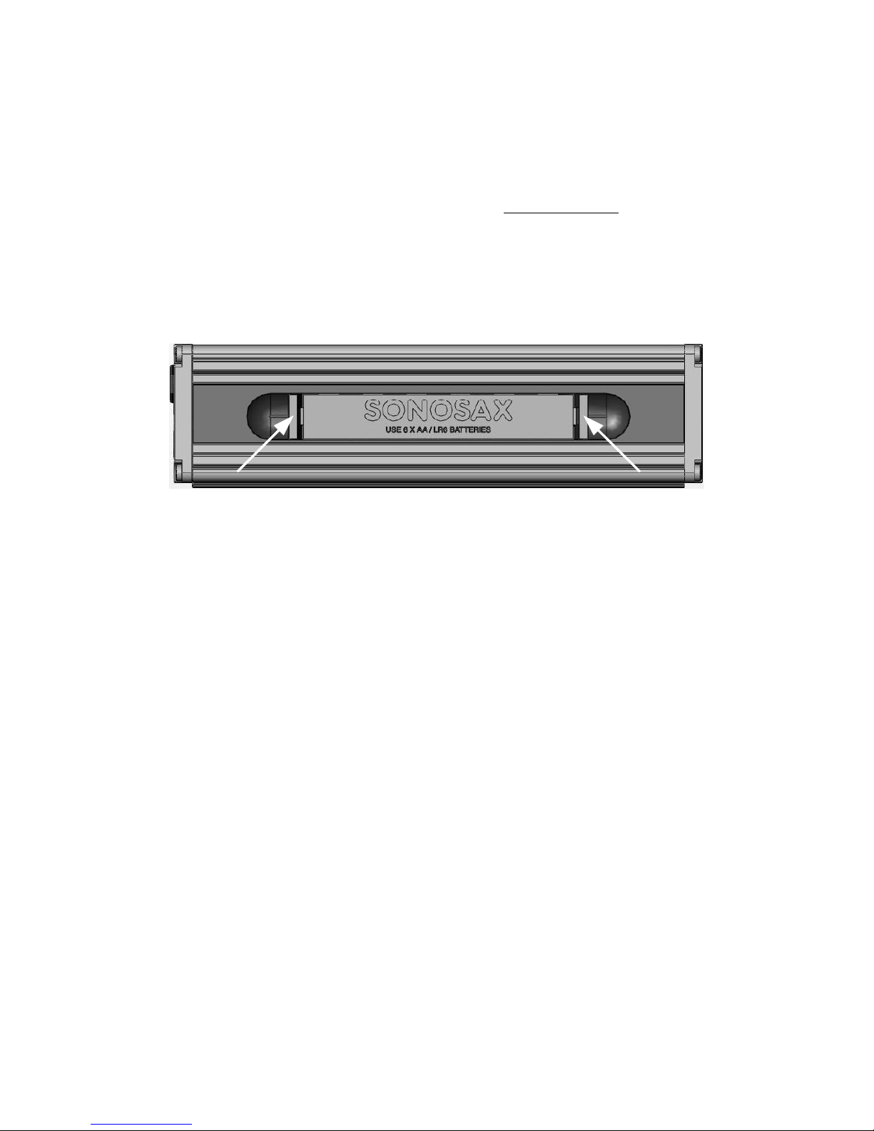
3.1.1 Opening the battery compartment
To open the battery compartment located on the rear of the unit, press on both locking pins on each side of
the compartment and slide out the battery holder.
Insert 6x AA-Cells ( LR6 ) and check for correct polarity
WARNING: Never leave discharged batteries in the compartment. To ensure an optimal running time,
use only premium quality rechargeable cells and check the expiry date
3.1.2 Closing the battery compartment
Slide the battery holder into its compartment. Its shape is designed so it can not be reversed. Press fermly
but without excessive force on both side of the battery holder to securely lock the pins.
3.1.3 Battery Low alarm
When the average voltage per cell reaches 1.05 Volt, an alarm is displayed on the LCD screen and a bip
tone is heard in the headphone. This alarm indicates that the SX-R4 still have a running time of aprox 10 to
20 minutes. When the voltage reaches 1.0 Volt per cell then the SX-R4 will automatically turns Off, thus
protecting your rechargeable batteries from excessive discharge.
NOTE: If a recording is in progress, the SX-R4 will stop the recording and then properly save the
recorded file on the hard disk before turning Off.
3.2 EXTERNAL DC POWER SUPPLY
SX-R4 Recorder can be powered from any regulated external DC power source from 6 to18 Volts. The DC
source must be capable to sustain at least 1,5A under 12 Volts DC. The average power consumption is
aprox 4 to 7 Watts depending on the microphone powering and the configuration of the SX-R4.

User manual SONOSAX SX-R4 Page 7 of 51
3.3 SWITCHING ON THE UNIT
PLAY REC
To power On the SX-R4, press simultaneously the Toggle switch and the Joystick to the right
A boot up screen is displayed for approx. 2 seconds and shows the following information:
• The remaining free available space on the hard disc and on the Compact Flash card
• A power indication of either the batteries or the external PSU by means of a bar graph
• Date and Time
• The currrent firmware version
NOTE: posting the remaining free space on the HD and on the CF card can take a certain time
depending on effective free space and the number of stored files.
As mentioned the SX-R4 can be powered either from the internal batteries or from an external DC source
.
• Using rechargeable batteries LR6 (AA-cell), NiCd ou NiMH:
Insert 6 batteries in the battery holder and switch On the unit as indicated here above. The LCDscreen
must turn On. If not:
Check that the batteries have been correctly inserted in the battery holder according to the
polarity.
Check that the batteries are properly charged .
• Using an external power source:
Connect the external DC power supply DC plug to the DC IN connector located on the right side of the
recorder and then and switch On the unit as indicated here above. The LCDscreen must turn On. If not:
Check that the external power supply Voltage is between 6 to 18Volts DC
Check that your power supply is strong enough to power on the SX-R4.
Check that the DC plug is correctly wired.
Pin 1 = GND or negative / Pin4 = +VDC or positive
3.4 SWITCHING OFF THE UNIT
Switching OFF the unit is controlled by the software. The fonction [SWITCH OFF] is accessed via the
contextual menu. ( see chapter 5.1.4 )
ON

User manual SONOSAX SX-R4 Page 8 of 51
4. DETAILED DESCRIPTIONS
4.1 LEFT SIDE PANEL
The left side contains the four Mic/Line inputs with their respective function switches as illustrated below:
4.1.1 Inputs [ IN1 to IN4 ]
Each of the input channels is transformer-less, electronically balanced is equiped in standard with a RF Filter
They corresponds to the input channels 1 to 4 of the internal matrixing system.
Input connectors are standard XLR-3 female where:
Pin1 = Gnd / Pin2 = High (+) / Pin3 = Low (-).
To connect an unbalanced source such as CD Player, Minidisk or else, pin 3 must be bridged to pin 1 (Gnd)
and wired to the Gnd on the source. Then use pin 2 for the unbalanced input signal.
WARNING: Never use the 48V Phantom in case of unbalanced connection or you could severly damage
the sourcing device !
NOTE: a stereo/dual-channel unbalanced Line input is available in the right side ( see chapter 4.2.1)
4.1.2 Phantom power [ 48V ]
This switch turns the 48V Phantom power On or Off on the corresponfing channel [IN1 à IN4]. In lower
position the 48V phantom is turned On to power condenser microphone. In upper position the Phantom
power is turned Off for connection of Dynamic microphone or any other analog sources.
WARNING: Never use the 48V Phantom when an external device other than a condenser microphone is
connected to the input or you may severly damage the output circuitries of that device.
Never use the 48V Phantom in case of unbalanced connection
NOTE: Almost all modern condenser microphones of the latest generation are operating under 48V
Phantom power. Because of the excellent common mode rejection (CMRR) it has been
decided to include only this kind of microphone powering on the SX-R4.

User manual SONOSAX SX-R4 Page 9 of 51
4.1.3 Pre-LF Cut Filter [ LF Cut ]
In lower position, this switch activates a passive low frequency cut circuitry (Pre LF-Cut). The Pre LF-Cut
filter circuitry is acting before the microphone pre-amplifier to attenuates the low frequencies of high level
that could affect the pre-amplifier and thus preventing an optimal setting of the input gain.
These low frequencies of high level can be generated, among other, by the microphone capsule especially
when recording outdoor in strong wind condition.
This Pre LF-Cut frequency is set at 135Hz and its slope is –6dB/octave.
4.1.4 Input Attenuator [ PAD ]
In lower position, this switch activates a 20dB Line attenuator [PAD] on the corresponding channel.
NOTE: The [PAD] should only be used for high level signals such as Line level coming from an
external device. For an optimanl signal to noise ratio it is recommanded not to use the PAD.
4.1.5 Phase reversal [
Ø]
In lower position, this switch reverses the phase of the input signal. It can be used to correct a reversed
cable wiring or to address a phase problem between two microphones due to their placement.

User manual SONOSAX SX-R4 Page 10 of 51
4.2 RIGHT SIDE PANEL
This panel contains followings connections:
• Headphone output [PHONES] on a ¼" jack
• Unbalanced stereo/dual-channel Line input [STEREO IN] with adjustable sensivity
• Unbalanced stereo/dual-channel Line output [SUB OUT] with adjustable output level
• External Video or Wordclock sync input [SYNC IN] and Wordclock output [WCKOUT]
• Digital Input AES 1 to AES 4 on a 26 pin multiway connector
• TimeCode input/output [TC] all format on a 5 pin Lemo
• External 6 to 18 Volts DC power supply [DC IN] on a 4 pin Hirose
• USB2 high seed connector [USB] for connection to any computer
• CompactFlash card slot
NOTE: The mating cable connector for the [STEREO IN] and the [SUB-OUT] a TA-3 female.
It is available under SONOSAX part nr SX860266 or Swtichcraft TA3FX
4.2.1 Headphone output [ PHONES ]
The headphone output on a 6,25mm ( ¼" ) jack allow connection of any mono or stereo headphone having
an impedance greater than 30 ohms.
The headphone level is adjustable by the Joystick ( see chapter 5.1.3 ). Pressing the Joystick to the left will
decrease the volume, pressing the Joystick to the right will increase the volume. The volume control is only
possible while in REC Mode or in PLAY mode.
The combination of tracks to be monitored and the monitoring mode is set in the [MONITORING] menu. It is
also possible to listen to each track individualy (mode SOLO , chapter 5.1.5)
The headphone connector [PHONE] is a stereo jack 6,35mm ( 1/4" ) where:
Sleeve = Gnd / Ring = Right / Tip = Left
WARNING: the headphone amplifier of the SX-R4 is quite poweful. It is recommanded to set the
headphone level for a reasonable loudness to protect your precious ears

User manual SONOSAX SX-R4 Page 11 of 51
4.2.2 Stereo/dual-channel Line Input [ STEREO IN ]
This unbalanced stereo/dual-channel Line Input is provided to connect any external device to the SX-R4
such as for example a SONOSAX SX-M32 or SX42 mixer, receivers of wireless systems or any other
external analog source.
The input signal corresponds to the Input channels 5 (Left) & 6 (Right) in the routing matrix system.
The retractable potentiometer adjusts the input sensivity from –10dBu to +25dBu to reach a digital
recording level of 0dBFS
The [STEREO IN] connector is a mini-XLR TA-3 male where:
Pin1 = Gnd, Pin2 = Left channel, Pin3 = Right channel.
4.2.3 Subsidiary Stereo Output [ SUB OUT ]
This unbalanced stereo/dual-channel Line Output is provided to send a rough pre-mix to any external analog
device such as for example a video camera, a transmitter or an alternative monitoring system.
This stereo/dual-channel [SUB OUT] is totally independent of the [PHONES] output and has its own
matrixing/mixing system. The combination of tracks and their routing to the Left or Right channel is similar to
the Monitoring system but is defined in the [LINE OUT] menu. It offers the same facilities including the Mono
summing and the M/S decoding ( see chapter 5.2.4 )
For ease of connections, this Line output is provided simultaneously on a TA-3 connecotr and a stereo Mini-
Jack wired in parallel. The mini-jack can also accommodate a headphone. (minimum impedance is 30ohms )
The retractable potentiometer adjusts the output Level between from –10dBu to +25dBu for 0dBFS.
The [SUB OUT] connector is a mini-XLR TA-3 male where:
Pin1 = Gnd, Pin2 = Left channel, Pin3 = Right channel.
4.2.4 External Sync [ SYNC IN ]
This SMA connector provides an input for an external Wordclock or a Video reference. Thus, it allows to
synchronize the A/D Converters of the analog inputs 1 to 6 on an external reference. The selection of the
synchronisation signal is achieved in the contexctual menu ( see chapter 5.2.2 )
4.2.5 Sync Out [ WCKL OUT ]
This SMA connector delivers a Wordclock sync signal. Its frequency depends either of the selected sample
frequency selected in the in the "Sampling settings" menu, or of the incoming frequency of the [SYNC IN] if it
is a valid WordClock, or of the sample frequency of the incoming AES input if a valid AES input in connected
on chanel 7/8 and properly routed in the matrix system.
4.2.6 External DC input [ DC IN ]
The SONOSAX SX-R4 can be powered by means of an external DC supply, either a main adapter or an
external high capacity battery bank. The voltage must be regulated between 6 to 18VDC
The average power consumption of the recorder is around 4 Watts. This represents a DC current of 330mA
under a supply voltage of 12Volts. However, while turning On the recorder the inrush current mayreach 2A,
therefore make sure that your external DC supply can sustain this peak of current
To ensure optimal performances we recommand you to use the optional main adapter available by your
local dealer.
the DC IN connector is a Hirose 4 pin female :
Pin 1 = Gnd ou negative / Pin4 = +V DC or positive; the voltage range is 6 to 18 Volts DC
The Hirose 4 pin male cable connector is available by SONOSAX or by your local dealer under references:
SONOSAX part nr SX860217 or Hirose HR10-7P-4P

User manual SONOSAX SX-R4 Page 12 of 51
4.2.7 Time Code Connector [ TC ]
The TimeCode input/output connector is a Lemo 5 pin, compatible with the Aaton wiring as below:
Pin 1 = Gnd
Pin 2 = Smpte Out
Pin 3 = not connected
Pin 4 = not connected
Pin 5 = Smpte In
The mating cable connector Lemo 5 pin is available by SONOSAX or by your local dealer under ref part
SONOSAX SX-860232 or Lemo FGG.0B.305.CLAD52
4.2.8 Digital Input [ ACCESSORY ]
This 26pin connector provides 4x AES/EBU digital audio inputs [AES1 to AES4]. The sync signals such as
the Sync In and the Wckl Out, the Time Code In and Out and the Monitor Out are internaly wired in paralel to
the corresponding main connectors. The serial bus is provided for future use
The mating cable connector is available under SONOSAX ref: SX-860570
Split cables wired for the 4x AES inputs are also available, please check with your local dealer.
4.2.9 USB2 connector [ USB ]
This connector is of USB2 type only. The SX-R4 is not compatible with anciliary USB 1.0 system
It allows to connect the SX-R4 to any computer ( PC or Mac ) providing with aa standard USB2 port. As soon
as connected, the SX-R4 will appear on the computer desktop as an external Harddisk drive. If a Compact
Flash card is inserted, it will also appears on the desktop.
WARNING: It is highly recommanded to use a Certified "USB 2 High Speed" cable. The data rate
transmission is so high that using a non certified cable may lead to unpredictable malfunctions
such as : Disk not recognized, SX-R4 nor appearing on your desktop, Windows error code 10
etc etc

User manual SONOSAX SX-R4 Page 13 of 51
4.3 FRONT PANEL
The front side of the SX-R4 contains all functions commonly used during a recording session. It has two
distinct sections: the analog section that controls the inputs channels and the User Interface that controls all
functions of the recorder
ANALOG SECTION [ IN1 to IN4 ]
This section covers the functions related to input control such as Gain level, channels linking. It also offers a
small 3 led peak-meters to visualize the modulation level, the eventual overloads and also to indicates the
Limiter activities.
4.3.1 Input Gain control [ LO-HI ]
The input gain is controlled jointly by the gain switches [ LO-HI ] and the gain potentiometer.
position High [ HI ] the input sensivity goes from –18,5dBu to –61,0dBu for 0dBFS
position Low [ LO ] the input sensivity goes from +1.5dBu to –38.5dBu for 0dBFS
position Low [ LO ] with [ PAD ] the input sensivity goes from +21.5dBu to –18.5dBu for 0dBFS
NOTE: Gain control should be used with care since the adjustment range is extensive. A signal level
set too high can cause distortion and will leave you with less headroom; a level set too low
causes a bad signal-to-noise ratio.
4.3.2 Channel Linking [ LINK ]
This switches allow to Link the Gain potentiometers of the input channels, thus a single potentiometer
controls two or more channels which ensure to keep the stereo balance of a stereo microphone, a M/S pair
or any other stereo source.
The Linking can be done either per pairs of channels such as for example 1&2 and/or 3&4, or for 3 channels
such as for double M/S system by linking channels 2 & 3 & 4, or even all 4 channels together as for the
Soundfied "B-Format" where all four channels will be linked to channel # 4 that has a quad potentiometer.
The Linkings are achieved as follow:
Channel nr 1: lower position = no linking
position 2 = Link channel 1 to channel 2. Fader nr 2 controls channels 1 & 2
position 4 = Link channel 1 to channel 4. Fader nr 4 controls channels 1 & 4
Channel nr 2: lower position = no linking
position 3 = Link channel 2 to channel 3. Fader nr 3 controls channels 2 & 3
position 4 = Link channel 2 to channel 4. Fader nr 4 controls channels 2 & 4
Channel nr 3: lower position = no linking
position 4 = Link channel 3 to channel 4. Fader nr 4 controls channels 3 & 4

User manual SONOSAX SX-R4 Page 14 of 51
4.3.3 Led's Peakmeters
This small peak meters has three distinct functions. It indicates not only the input level of the channel but
also the Limiter activities as soon as the signal reaches the threshold level and the eventual overloads.
These meters are connected at the input of the A/D Converter
Level indication:
Green Led: the modulation reaches an internal level of aprox -20dB.
Yellow Led: the modulation reaches the nominal internal level 0dB (-18dBFS)
Red Led: the modulation reaches an internal level of aprox +10dB
Limiteurs: The Limiteur activity is shown by lighting simultaneously the Red and the Green led's for
a period of aprox 1 second
Overloads: the overload is indicated as soon as the clipping level is reached 0dBFS. In this case all
led's light at the same time
NOTE: The Leds intensity vary automatically depending on ambiant light. It is controlled by the light
sensor located on the left side of the Joystick
4.3.4 Input Limiter
Each of the 4 input channel is equiped with a protection Limiter which is part of the microphone pre-amplifier
design. The Limiter is automatically activated 2dB below the clipping level of the A/D converter (–2dBFS)
and can not be de-activated. The Threshold is set at factory and can not be modified by the user
The Limiter activities is indicated by the 3 Leds Peak-Meter by lighting the Red and the Green Led for a
period of aprox 1 second.
4.3.5 Red Led [ OVD LINE]
This Red Led indicates the eventual overload on the Line Inputs 5 & 6. It lights as soon as the clipping level
of the A/D Converter 5&6 is reached

User manual SONOSAX SX-R4 Page 15 of 51
5. USER INTERFACE
PLAY REC
5.1.1 PRINCIPLE OF OPERATION
Status
The Status of the SX-R4 is displayed by means of the Red and the Green leds and by the LCD Display. The
following status are possible:
• RECORD READY
the Red LED is flashing, the SX-R4 is ready to start recording.
• RECORDING
the Red LED lights On steady, confirming that a recording is in progress
• PLAYING
the Green LED lights On steady, a Take is playing
• PLAY PAUSE
the Green LED flashes, indicating that the loaded Take is currently paused.
• PLAY STOP
A Take is loaded ready to be played, no LED lights on, nor flashes
Main scren display
The main working screen [ TRACK MONITORNG ] displays the Level Meters of the 8 tracks.
The global meter's range is 72dB with following resolutions :
1dB steps from –72dBFS up to –24dBFS
0.5dB steps from –23.5dBFS up to 0dBFS.
A configurable reference line can be displayed at -9, -12, -18, or –20 dBFS (see configuration menu)
Convention for displayed informations and function keys
The last line on the screen displays the Joystick's function.
By default, pushing the Joystick Up or Down modifys the parameters, to the Right will select the parameter
and to the Left cancel the action or steps back in the contextual menu.
A single Arrow symbol denotes that an action is achieved by briefly pushing the Joystick.
A double Arrow symbol means that the Joystick must be pushed longer to achieve the action.
A round Dot symbol denotes a pressure on the center of the Joystick
Jo
y
stic
k
LCD Screen
10 lines x 17 characters
Li
g
ht
Green LED
Red LED
To
gg
le Switch
User manual SONOSAX SX-R4 Page 16 of 51
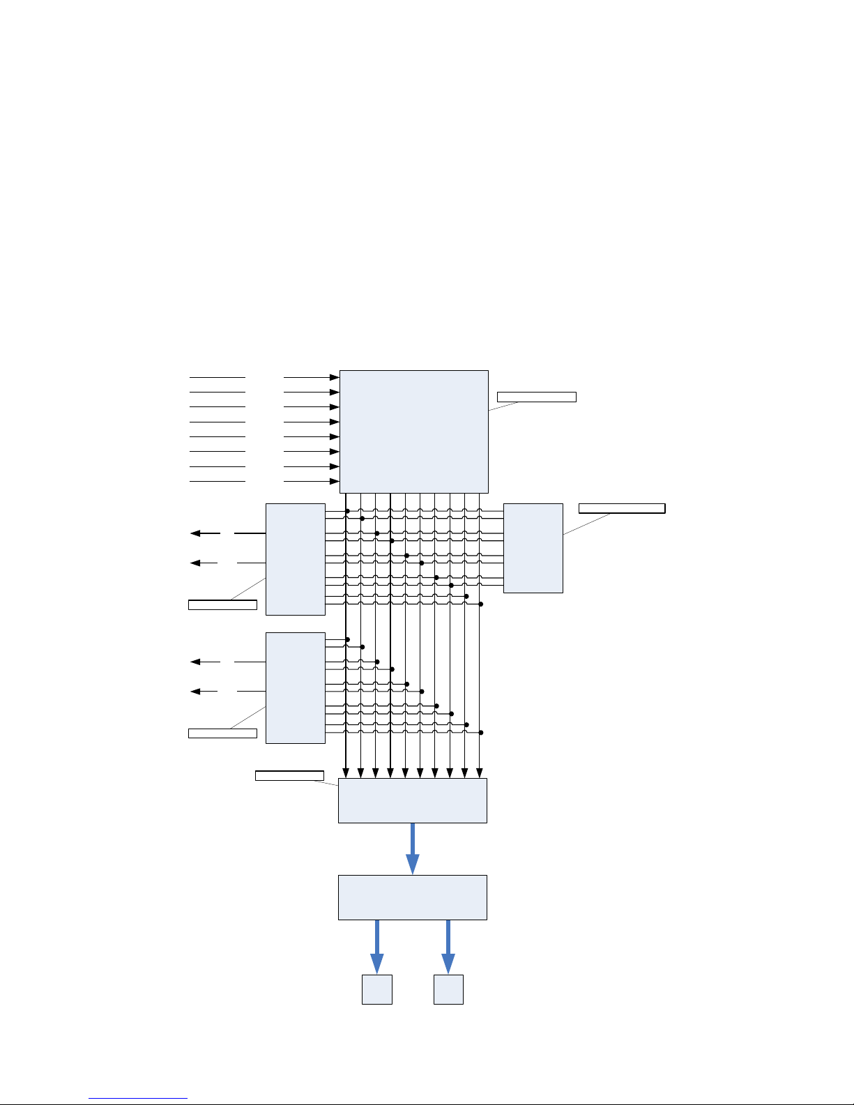
5.1.2 ARCHITECTURE - AUDIO PATH
The SONOSAX SX-R4 offers 14 physical input channels, 6 analog and 8 digital. Up to 8 of these physical
input channels can be assigned to any of the 10 available tracks, and any analog/digital channel
combination is possible. These physical channels are groupped per pair as follow:
• 1, 2 : either MIC/LINE input 1 & 2 or AES 1
• 3, 4 : either MIC/LINE input 3 & 4 or AES 2
• 5, 6 : either LINE input 5 & 6 or AES 3
• 7, 8 : AES4 only
The routing Matrix allows to asssign and mix any of the input channels to any of the 10 available tracks.
The first 8 tracks are dedicated to the hard disc (HD) and the 2 additional tracks are dedicated to the
Compact Flash card (CF).
For Monitoring purposes, you can configure and listen to any combination of these 10 tracks. However, the
display shows only the Peak meters of the 8 hard disk's tracks
Channel 1
Channel 2
Channel 3
Channel 4
Channel 5
Channel 6
Channel 7
Channel 8
Mixer coeficients
Left
Line out config
Monitor config
Right
Bits per sample
HDD CF
Modulometers values
Monitor
Wave encoder
FAT32 / ATA layer
Mixer
Tracks
1 2 3 4 5 6 7 8 9 10
Modulo-
meters
Left
Right Line out
User manual SONOSAX SX-R4 Page 17 of 51
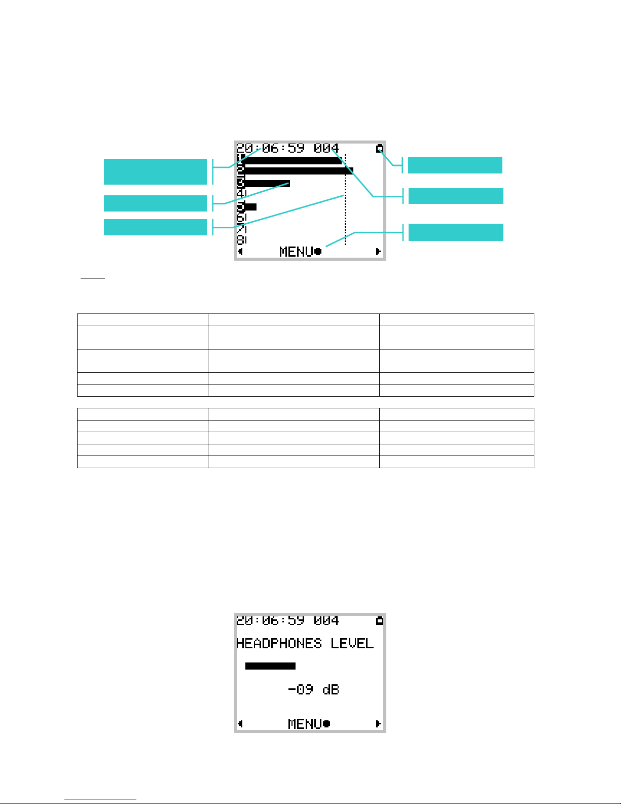
5.1.3 TRACK MONITORING
The TRACK MONITORING is the default page beeing displayed by the SX-R4. The track numbering from 1
to 8 is always displayed and is related to the HardDisk tracks. The number of each active track in use
(assigned in the matrix ) is posted in reverse video.
Note: The peak meter reference level can be set in the "Configuration" menu.
The actions or functions of the Joystick and the Toggle switch are described as follow:
Joystick Short pressure Long pressure
LEFT Reduce the headphone volume in
1dB steps
Reduce the volume continuously
down to minimum
RIGHT Increase the headphone volume in
1dB steps
Increase the volume continuously
up to maximum
UP and DOWN SOLO MONITORING
CENTER Call the contextual Menu page Lock/Unlock the Joystick action
Toggle switch Short pressure Long pressure
RIGHT Start recording
RIGHT while recording Add an Index ** Stop recording
LEFT Call and Play the last take
LEFT while playing Pauses at current position Stop playing
** Index = New TAKE
A brief pressure to the Right on the toggle switch while Recording will automatically create a new [TAKE].
This new Take nr is automatically incremented by 1.
The audio files of this new Take are cut at the sample level ( precision of one sample ). Takes can then be
seamlessly re-assembled in an editing software with the help of the TimeCode.
Pressing the Joystick to the Left or to the Right displays temporarily will post a temporary screen showing
the headphone level by means of a bar graph. The headphone level is adjustable in 1dB steps from –30dB
to +18dB.
Reference Level
Track Meterin
g
Timecode
(
HH :MM :SS
)
Batter
y
level indicato
r
TAKE Nr
Function of the
User manual SONOSAX SX-R4 Page 18 of 51
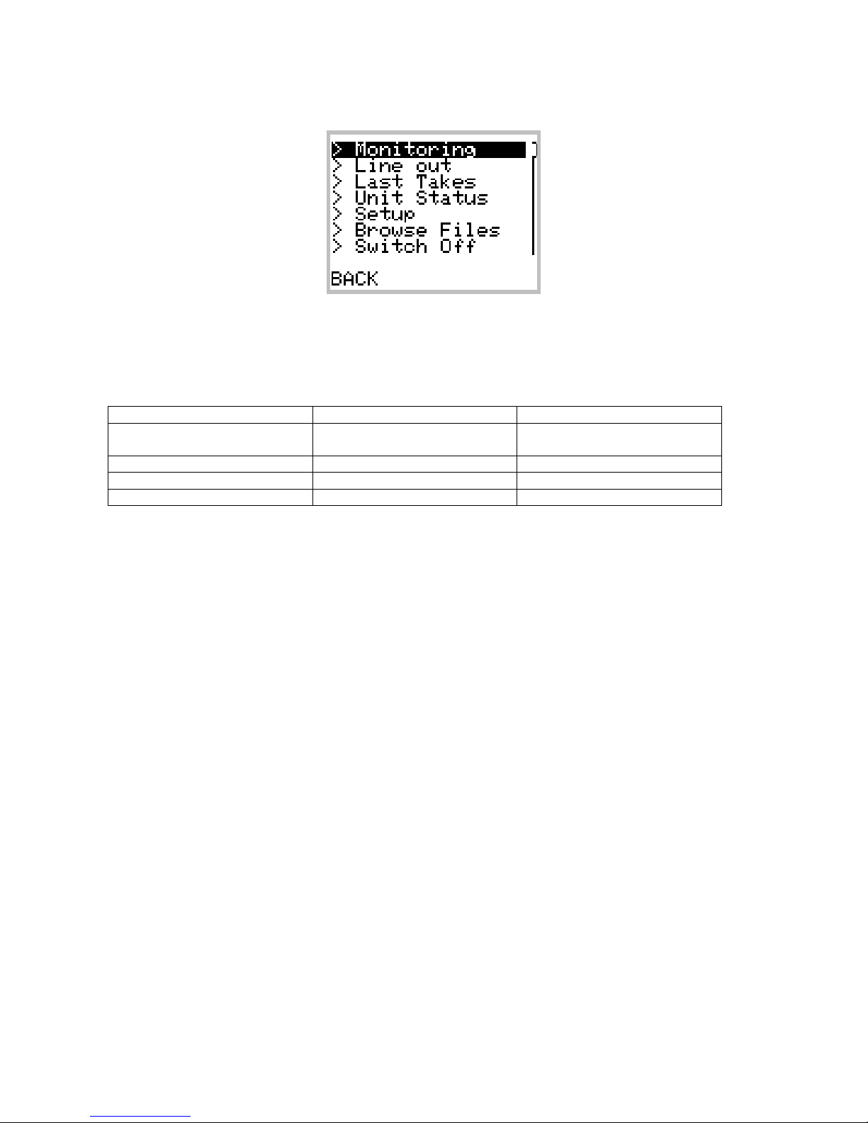
5.1.4 CONTEXTUAL MENUS
The Contextual Menu allows a quick navigation between the different pages and configurations menu of the
SX-R4. The Contextual Menu can only be accessed from the Track Monitoring page ( not while in Solo
Monitoring Mode ) by a pressure on the center of the Joystick.
Joystick Short pressure Long pressure
LEFT Steps back from the menu to the
Tracks Monitoring page
RIGHT and CENTER Confirm the selection
UP Scroll the selection upward
DOWN Scroll the selection downward
The possible choices in the Contextual Menu depend on the current "Status" of the SX-R4 as described here
below:
While Recording:
• >Monitoring
• >Line Out
• >Unit Status
While in Record Ready:
• >Monitoring
• >Line Out
• >Last Takes
• >Unit Status
• >Setup
• >Browse Files
• >Switch Off
While Playing or in Pause:
• >Last Takes
• >Monitoring
• >Line Out
• >Unit Status
• >Delete Take
While in Stop:
• >Last Takes
• >Exit Player Mode
• >Monitoring
• >Line Out
• >Unit Status
• >Browse Files
• >Delete Take
• >Switch Off

User manual SONOSAX SX-R4 Page 19 of 51
5.1.5 SOLO MONITORING
The [SOLO MONITORING] page is accessed from the [TRACK MONITORING] page by pressing the
Joystick Up or Down. It allows you to Monitor in mono any individual track or a specific pair of tracks.
The page beeing displayed is visually almost identical to the [TRACK MONITORING] page with the
expection that a round dot indicates the selected track being soloed.
The track selection sequence is as follow: 1, 2, 1+2, 3, 4, 3+4, 5, 6, 5+6, 7, 8, 7+8.
The UP key moves the selection upward; the DOWN key moves the selection downward
The Solo Monitoring is only possible with active (assigned) tracks
Joystick Short pressure Long pressure
LEFT Reduce the headphone volume in
1dB steps
Reduce the headphone
volume continously
RIGHT Increase the headphone volume in
1dB steps
Increase the headphone
volume continously
UP Select the previous track
DOWN Select the next track
CENTER Returns to the
TRACKS MONITORING
Lock/Unlock the Joystick
The example above shows a configuration of 4 active (or assigned ) tracks: 1, 2, 3, and 5.
Track 1 being currently selected for Solo Monitoring.
In this particular case, the selection sequence for the Solo is: 1, 2, 1+2, 3, 5

User manual SONOSAX SX-R4 Page 20 of 51
5.1.6 MONITORING
This Monitoring page is used to configure and mix the 10 tracks of the SX-R4 for it's headphone output.
The configuration of the monitoring is done by means of a specific menu as shown below :
The Monitoring is always configured per pair of tracks ( 10 tracks = 5 pairs of tracks )
The table below shows the available choices and their respective monitoring results on the stereo
headphone output for the pair of tracks 1 and 2.
Monitoring Mode Result on the Left channel Result on the Right channel
--- --- ---
MONO 1 + 2 1 + 2
STEREO 1 2
REV STEREO 2 1
MS 1 + 2 1 – 2
MONO L 1 + 2 ---
MONO R --- 1 + 2
The table below descibes the actions of the Joystick :
Joystick Short pressure Long pressure
LEFT Change the monitoring mode.
RIGHT Change the monitoring mode.
UP Move the selector upward
DOWN Move the selector downward
CENTER Save the modifications and
return to the previous Menu
Note: If a pair of tracks is not activated (not assigned) the only possible value is : " --- " (No Monitoring)
Other manuals for SX-R4
3
Table of contents
Other Sonosax Recording Equipment manuals


