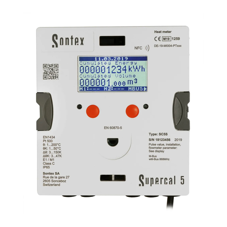
Sontex Supercal 5 I User manual

Instructions for Use
Supercal 5 I

2Instruction for use | Supercal 5
Read this manual thoroughly before using the calculator.
Be sure to read the “Safety” section (page 10) to ensure proper use of the
calculator.
After reading this manual, keep it easily accessible so that it is ready for future
reference.
Legal Provisions
The information contained in this document is the property of Sontex SA. Publication, in
whole or in part, requires the written consent of Sontex SA. Any internal reproduction in-
tended for evaluation of the product or its proper use is permitted and not subject to au-
thorisation.
Warranty
Please contact your local Sontex representative for warranty information.
Trademark
M-Bus is a European standard (EN 13757-2/3) for reading heat meters.
Modbus® is a registered trademark of Schneider Electric and is licensed by the Modbus
Organization, Inc.
BACnet® is a registered trademark of the American Society of Heating, Refrigerating and
is available at the following link:
http://www.bacnetinternational.net/btl/index.php?m=269

3Instruction for use | Supercal 5
Table of Contents
1. Notes on this Document 7
1.1 Scope of Validity 7
1.2 Target Groups 7
1.3 Storage of Document 7
1.4 Further Information 7
1.5 Symbole 8
2. Safety 9
2.3.2 Operational safety 10
2.3.3 Product Safety 10
3. Description 11
3.1.1 Front Panel 11
3.1.1 Scope of Delivery 13
3
3.3.1 CE-Symbol 13
4. Installation 14
4.1 Acceptance of Goods 14
4.2 Transporting and Storing the Calculator 14
4.3 Checking the Scope of Deliver 14
4.4 Structure and Components of the Calculator 14
4.4.1 Calculator Cover 15
4.4.2 Calculator Lower Part 15
4.5 Dimensions 16
4.6 Mounting 16
4.6.1 Before Mounting 16
4.6.2 Wall Mounting 17
4.6.3 Top Hat Rail Mounting 18
4.7 Installation Instructions for Temperature Sensors 18
4.7.2 Connection of 4-Wire Temperature Sensors 20
4.7.2.1 Wire Cable Sensor with 2-Wire Calculator 20
4.7.3 Installation Guidelines for Temperature Sensors According to EN1434 21
4.7.3.1 Compliance With the Operating Conditions According to MID for the
Temperature Sensors 21
4.8 Installation Check 21
5. Wiring 23
5.1 Wiring Requirements 23
5.2 Opening the Calculator 23
5.3 Wiring 23
5.4 Power Supply at the Calculator 24
5.4.1 Power Supply Modules 24
5.5 Connecting Sensors 24
5.5.1 Pulse Input for Volume Counting 24

4Instruction for use | Supercal 5
5.5.1.1 Technical Characteristics of the Pulse Input for Volume Counting 24
5.5.2 Two Additional Pulse Inputs 25
5.6 Connecting Outputs 25
5.6.1 Two Open-Collector Pulse Outputs 25
5.6.1.1 Technical Characteristics of the Two Open-Collector Pulse Outputs 26
5.7 M-Bus Communication 27
5.7.1 Timing M-Bus Communication 27
5.7.1.1 Technical Characteristics of embedded M-Bus 27
5.8 Radio Modules 28
5.8.1 Radio Telegram 28
6. Operation 29
6.4 Menus 30
6.5 Commissioning 30
6.6 Main Menu 31
6.7 Overview Menu 34
6.8 Metrological Setup 34
6.11 Service 40
6.12 Sealing 42
6.13 Nowa / Unicon 42
6.14 Save Operating Data 42
6.14.1 Data Backup 42
7. Commissioning 44
7.1 Commissioning of the Supercal 5 44
7.1.1 Checking Date and Time 44
7.1.2 Flow Control 44
7.1.3 Checking the Temperatures 44
7.2 Uses 44
7.2.1 Flow Calculation 44
7.2.1.1 Reaction time and Accuracy of the Flow Calculation 45
7.3 Software Superprog Windows and Superprog Android. 45
7.3.1 Download the Superprog Windows and Superprog Andorid. 45
7.3.1.1 Solar and Refrigeration Systems 45
7.3.1.2 Tariff Functions and/or Status Message Signal 45
7.3.1.3 Power Supply 46
7.3.1.4 Error Output 46
8. Maintenance 46
8.1 Cleaning 46
9. Troubleshooting 46
.1 General Troubleshooting Procedure 46
.2 Fault Indication 46
.3 Error Messages 47
.4 Troubleshooting M-Bus 48
.5 Troubleshooting MODBUS 48
10. Decommissioning 48
10.1 Exchange and Return 48
10.2 Disposal 48
10.2.1 Disposal 48

5Instruction for use | Supercal 5
11. Technical Information 49
11.2 Power Supplies 50
11.2.1 Mains Modules 50
11.2.2 Battery Modules 50
11.2.3 Estimating the Battery Life of an M-Bus Application 50
11.3 Measurement concept 50
11.4 Arithmetic Logic Unit 51
11.5 Flow Sensors 51
11.6 Flow Measurement 51
11.7 Flow Calculation 52
11.7.1 Calculation of the Flow Rate with Conventional Flow Sensors 52
11.7.2 Calculation of the Flow Rate with Fast Flow Sensors 52
11.8 Temperature Measurement 52
11.8.1 General Information 52
11.8.2 Permissible Errors and Limit Values 53
11.10 Calibration and Measurement Data 54
11.11 Nowa 54
12. Notes on Project Planning 56
12.1 Safety and Security 56
12.2 Local Regulations 56
12.3 Power Supply 56
12.4 Lightning protection 56
12.5 Bus Facilities 56
12.6 Refrigeration Plants 57
12.7 Assembly 57
12.8 Lead Sealing 57
7
12.10 Installation Information 57
12.11 Minimum Distances 57
13. Appendix 58
13.1 Extra Information for Supercal 5 S 58
13.1.1 Cut off Function of the Superstatic 440 58
13.4 Technical Data Flow sensor Superststic 440 62
13.5 Optional Communication Modules Overview 63
13.6 Software 63
14. Return of good Form 64
15. Country List 65
16. Declaration of Conformity 65

6Instruction for use | Supercal 5

7Instruction for use | Supercal 5
1. Notes on this Document
This manual provides all the information required for the correct use of the equipment
and disposal.
1.1 Scope
This documentation refers to the Sontex Supercal©5 I and Supercal©5 S.
1.2 Audience
This document is intended for system operators and installers of the calculator
or heat meter.
1.3 Accessibility of the Document
The system operator must ensure that this document is accessible to the responsible
personnel at all times. If the original document is lost, an up-to-date version can be down-
loaded from our extranet (https://extranet.sontex.ch/index/).
1.4 Further Information
Links to further information can be found at www.sontex.ch.

8Instruction for use | Supercal 5
1.5 Symbols
Symbol Signicance
DANGER
DANGER!
Failure to observe these warnings leads to fatal or serious injury.
WARNING
WARNING!
Failure to observe these warnings may lead to fatal or serious injury.
CAUTION
CAUTION!
Failure to observe these warnings may lead to moderate injury.
NOTICE NOTICE!
Failure to observe these warnings may result in damage to property.
Reference
safety relevant.
Documentation
Reference to other documentation.
?Help
Help in case of problems.
Visual check
Check that the item is in order.
CE-Marking
The calculator meets the requirements of the European
directives 2014/32/EU (MID) and RED 2014/53/EU.
Disposal
This symbol indicates that electrical and electronic equipment must
be disposed of separately. Do not dispose of the calculator with
household waste.

Instruction for use | Supercal 5
2. Safety
Safe operation of the calculator can only be guaranteed if the operating instructions have
been read and the safety instructions contained therein have been observed.
Further information and data can be found in the product’s catalogues and data sheets,
through your local representative, or on the Sontex homepage at www.sontex.ch.
All technical data are without guarantee.
Technical changes may be made at any time.
In case of doubt, the text of the English Instructions For Use applies.
2.1 Personnel Qualication
Personnel responsible for installation, commissioning, diagnosis and maintenance must:
Be authorized by the plant operator.
Be familiar with the relevant standards and directives and with national regulations.
Read and understand instructions and additional documentation as well the relevant
Follow instructions and general conditions.
Be trained in the handling of hazards and risks involved in the installation and
operation of electrical devices and systems.
Operating personnel must also:
Be instructed and authorized by the plant operator in the task
requirements.
Follow the instructions in this document.
2.2 Intended Use
It can be used universally in industry, district heating and building services engineering.
and changes to the device must not be made.
-
ulations as well as the manufacturer’s instructions must be observed. The manufacturer
assumes no responsibility for changes to the data relevant for calibration and measure-
ment if the factory seal has been broken.
If several heat meters are used in one billing unit, the same device types and installa-
tion positions should be selected to ensure that heat consumption is measured as fairly
as possible.
If water based cooling liquids (Glycol) are used, then the Superstatic 440 flow sensor
must be used (mechanical flow sensors cannot be used).
2.3 Safety Instructions
2.3.1 Occupational Safety
When working on and with electronic devices:
Wear the protective equipment required under national
regulations.

10 Instruction for use | Supercal 5
2.3.2 Operational safety
Risk of injury!
Operate the device only when it is in a fault-free and safe condition.
The operator is responsible for the trouble-free operation of the device.
Modications to the device
risks:
Sontex SA.
Repair
To ensure continued operational safety:
Only carry out repairs to the electronic device if these are expressly permitted.
Observe the national regulations concerning the repair of an electrical and electronic
devices.
Only use original Sontex spare parts and accessories.
Environmental requirements
If the plastic housing of the Supercal 5 is permanently exposed to certain vapour-air mix-
tures, the housing may be damaged.
For use in areas subject to approval: See the information on the nameplate.
2.3.3 Product Safety
The Supercal 5 has been built and tested in accordance with good, state of the art engineer-
ing practice to ensure it’s safe operation; it left the factory intechnically perfect condition..
It meets the general safety and legal requirements. It also conforms to the EC directives
-
ing the CE mark.

11Instruction for use | Supercal 5
3. Description
3.1 Identication
3.1.1 Front Panel
The following data according to PTB/MID can be found on the front panel:
Data on the front panel
Manufacturer or customer logo Sontex
Product designation Supercal 5*
CE marking
Item number SC5Ixxxxx
Serial number/Year S/N xxxxxxxx
QR Code
Enviroment class according to OIML or EN 1434 C
Electrical/Mechanical class according to OIML or EN 1434 E1/M1
Protection class according to OIML or EN 1434 IP65
Temperature range (Θ)1..200 °C
Temperature difference (ΔΘ) 3..150 K
Temperature range cooling (ΘK) 1..200 °C
Temperature difference cooling (ΔΘK) 3..150 K
Pulse factor See Display
Installation See Display
Resistor Pt500
Approval mark
Flowmeter parameter: qp, qi, qs, DN, PN. See Display
M-Bus Interface EN 13757-2
Standard optical interface EN 60870-5
Optional Radio Interfaces Sontex radio 433 MHz wM-Bus 868 MHz No Radio
NFC Chip Location NFC )))
Sontex Address Rue de la Gare 27, 2605 Sonceboz. Switzerland
** According to production year.

12 Instruction for use | Supercal 5
EN1434
Pt 500
E1 / M1
IP65
EN 6070-5
Type: SC5I
S/N: 26277017 2021
Pulse value, installation,
flowmeter parameters:
See display
M-Bus
wM-Bus 868MHz
Sontex SA
Rue de la Gare 27
2605 Sonceboz
Switzerland
NFC
Calculator
Heating/Cooling
θ: 1...200°C
∆θ: 3...150K
θK: 1...200°C
∆θK: 3...150K
M21 1259
DE-21-MI004-PTB002

13Instruction for use | Supercal 5
3.2 Scope of Delivery
The scope of delivery of the Supercal 5 includes:
Installation guide
Stickers (seals)
Optional modules
3.3 Certicates and Approvals
The Supercal 5 and the optional pair of temperature sensors meet the requirements of Di-
(Measurement Instruments Directive, MID), as well as OIML R75 and EN-1434.
also have a type approval (incl. conformity assessment) in accordance with MID.
3.3.1 CE-Symbol
The product meets the requirements of the harmonized European standards. Thus it meets
-

14 Instruction for use | Supercal 5
4. Installation
Installation and commissioning of a heat measuring point should only be carried out by au-
thorised, specialist personnel in compliance with the appropriate standards and local safety
and installation regulations.
According to EN 1434-2 and EN 1434-6, the installation guidelines must be followed. A heat
measuring point will only meet the planned accuracy and reliablity requirements if these
are complied with.
4.1 Acceptance of Goods
After receiving the goods, check:
The packaging and contents are not damaged
The delivered product is complete
Compare the scope of delivery with your order details.
4.2 Transporting and Storing the Calculator
can be found in the chapter Technical Information.
Observe the following points:
For storage and transport the device must be protected against impact damage. The
original packaging offers optimum protection for this.
should be limited to maximum 48 hours.
4.3 Checking the Scope of Delivery
Check the scope of delivery for completeness and possible damage. Contact your dealer or
Sontex SA in case of faulty delivery.
4.4 Structure and Components of the Calculator
The Supercal 5 calculator consists of:
A cover section, containing measuremant and calibration components
A lower, body section
The calculator’s modular design allows for low storage costs and simple and effective meter
replacement after the calibration validity has expired.
Only the cover section of the calculator needs to be replaced, the body section of the
remains in situ.

15Instruction for use | Supercal 5
4.4.1 Calculator Cover
4.4.2 Calculator Body
1Sontex or customer logo
2Dot-Matrix Display
3Brackets for Housing opening/closing
4Two Status LED
5Two operating buttons
6Optical interface
7NFC Interface
8External mains / battery supply
9Terminal block
10 Rubber gommets (IP65)
11 Strain reliefs for connection cable and earthing
12 Two slots for optional communication modules
13 Wall mounting sliders
The following elements are located in cover and body part of the calculator:
1
2
3
4
7
12
5
6
8
9
10
13
11

16 Instruction for use | Supercal 5
4.5 Dimensions
159.6
163.6
136.3
138.3
49
5.5
23.2
175.1
95.08
143
158
53.5
3.9
4.6 Mounting
4.6.1 Before Mounting
All cables must be laid at least 300mm away from power and high-
frequency cables.
calculator must be avoided.
The calculator must generally be mounted away from the hot or cold
pipes.
Ensure no condensation can run into the calculator along the connected
lines.
If there is a risk of vibration in the piping system, the calculator should
be mounted separately on the wall.
mounted separately.
that there are no foreign bodies in the pipeline.
The lines must be vented during commissioning. Air in the system or in
Only use suitable new sealing material.
The tightness of the various connections must be checked.
Lightning protection cannot be guaranteed; this must be ensured via
the house installation.

17Instruction for use | Supercal 5
Check the design data of the components.
check the type plates!
The permissible ambient temperature for the calculator is 5 ... 55 °C.
The installation and project planning regulations must be adhered to.
The calculator faceplate and all nameplates must be legible.
The complete heat meter consists of the following three subunits:
Flow sensor
Calculator Supercal 5
Temperature sensor (2- or 4-wire technology) with or without pockets
sensor resistance set in the calculator must also match the temperature sensor.
The Supercal 5 calculator offers the following mounting options:
4.6.2 Wall Mounting

18 Instruction for use | Supercal 5
4.6.3 Top Hat Rail Mounting
Monté
Installation
4.7 Installation Instructions for Temperature Sensors
Great care must be taken in selecting and installing temperature sensors. Errors made here
cannot be compensated even by the best calculator.
CAUTION
Take care when installing the temperature sensors!
Incorrect removal of directly immersed temperature sensors may result in an acci-
dent! Installation and removal may only be carried out by authorized and competent
personnel.
NOTICE
Cables must be shielded against electromagnetic interference!
If there is a risk of electrical or electromagnetic interference, temperature sensors in
2- and 4-wire technology with shielded cables or shielded cables must be used at the
connection terminals. The shielding should be connected to the appropriate electrical
ground in the calculator. Risk of interference increases with the length of the sensor
cables!
The connection cables must not be separated, extended or shortened!
The sensors are exactly computer paired in the factory and may only be used in the
original pairs!
Installation with cable lengths over 3 m
For installations with cable lengths over 3m or with unequal cable lengths,
we recommend the use of 4-wire temperature sensors. The maximum cable
length of the 4-wire temperature sensors is 50 m

Instruction for use | Supercal 5
Only platinum temperature sensors with type approval in the Pt500 version are recommend-
ed. These must be paired and used in two-wire technology up to a cable length of 3 m. The
connecting cables must not be separated, extended, or shortened.
For lengths of more than 3 m, we recommend the use of adequately shielded cable runs of
equal length. The approval of the Supercal 5 allows 2-wire temperature sensors to be used
up to a maximum length of 15 m and 4-wire temperature sensors up to a maximum cable
length of 50 m. Supercal 5 can be used with a maximum cable length of 50 m.
The temperature sensors should preferably be installed directly and without pockets for
low-temperature heating systems due to the minimum temperature spread. This allows even
the smallest temperature differences to be determined without delays and heat dissipation
errors.
In pipelines up to DN 150, temperature sensors may be installed directly or using pockets.
The sensor tip should be located as close as possible to the middle of the pipeline.
Extensive information on the subject of temperature sensors can be found in our Sontex
temperature sensor overview at: www.sontex.ch/downloads/ under the heading tempera-
ture sensor 460.
4.7.1 Installation of Temperature Sensors
5678
5/6
Temperature high
7/8
Temperature low
r w r w
Since it is not the absolute temperature but the exact temperature difference that is im-
portant when measuring the heat quantity, both sensor cables must be of identical length
(resistance). The sensors are very accurately computer paired in the factory and may only be
used in the original pairs.
EN1434-2 2004 prescribes the following maximum cable lengths for 2-wire temperature
sensors:
Wire cross-section Maximum cable length
Pt500
0,22 mm212,5m
0,50 mm225,0 m
0,75mm237,5 m
1,50mm275,0 m

20 Instruction for use | Supercal 5
4.7.2 Connection of 4-Wire Temperature Sensors
For installations with cable lengths over 3m or with unequal cable lengths, we recommend
the use of 4-wire temperature sensors. The maximum cable length of the 4-wire tempera-
ture sensors is 50 m.
The connection cable must have four wires with a cross-section of at least 0,5 mm2
The insulation of the temperature sensor cables can be PVC or silicone. Sontex recommends
the use of silicone insulation.
1
5
6
2
3
7
8
4
wrr wwr w
1/5 and 2/6
Temperature high
3/7 and 4/8
Temperature low
r
1
5
6
2
r
r
w
w
3
7
8
4
r
r
w
w
4.7.2.1 Wire Cable Sensor with 2-Wire Calculator
56
rw
78
rw
5/6
Temperature high
7/8
Temperature low
5/6
Temperature high
7/8
Temperature low
Other manuals for Supercal 5 I
1
Table of contents
Other Sontex Measuring Instrument manuals
Sontex
Sontex Supercal 739 Manual

Sontex
Sontex Superstatic 470 SPF User manual

Sontex
Sontex Supercal 739 User manual
Sontex
Sontex Superstatic 749 User manual
Sontex
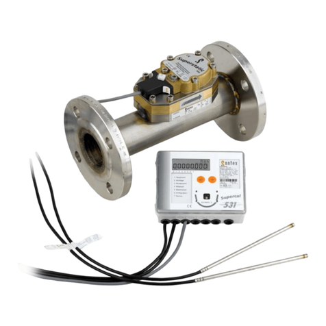
Sontex Superstatic 440 User manual
Sontex
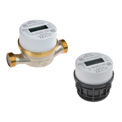
Sontex Superaqua 1 User manual
Sontex
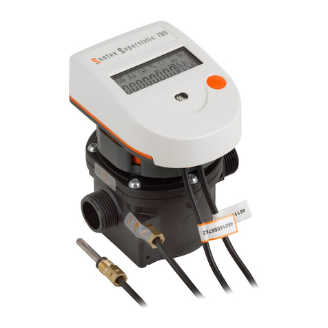
Sontex Superstatic 789 User manual
Sontex
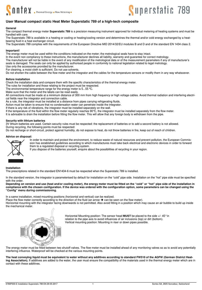
Sontex Superstatic 789 User manual
Sontex
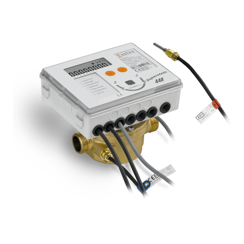
Sontex Superstatic 449 Instruction sheet

Sontex
Sontex Superstatic 789 User manual

