manuals.online logo
Brands
  1. Home
  2. •
  3. Brands
  4. •
  5. Sontex
  6. •
  7. Measuring Instrument
  8. •
  9. Sontex Superstatic 789 User manual

Sontex Superstatic 789 User manual

0789P300-E Installation Superstatic 789 EN 29-05-2017 1 Sontex SA, 2605 Sonceboz, Switzerland
User Manual compact static Heat Meter Superstatic 789 of a high-tech composite
General
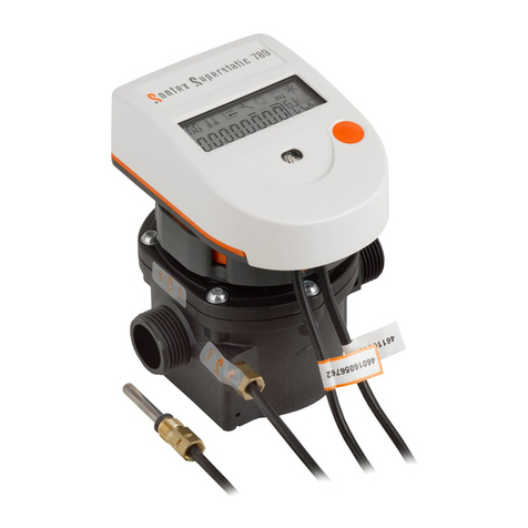
The compact thermal energy meter Superstatic 789 is a precision measuring instrument approved for individual metering of heating systems and must be
handled with care.
The Superstatic 789 is available in a heating or cooling or heating/cooling version and determines the thermal and/or cold energy exchanged by a heat-
bearing fluid in a heat exchanger circuit.
The Superstatic 789 complies with the requirements of the European Directive MID 2014/32/EU modules B and D and of the standard EN 1434 class 2.
Important!
The energy meter must be used within the conditions indicated on the meter; the metrological seals have to stay intact.
In the event non compliancy to these instructions, the manufacturer declines all liability, warranty and guarantee for correct metrology.
The manufacturer will not be liable in the event of any modification of the metrological data or of the measurement parameters if any of manufacturer’s
seals is damaged. The seals can only be applied by authorised people in conformity to national legislation related to legal metrology.
Use only the accessories provided by the manufacturer.
For cleaning, a moist cloth is sufficient. Do not use solvents.
Do not shorten the cable between the flow meter and the integrator and the cables for the temperature sensors or modify them in any way whatsoever.
Before installation
Check the installation data and compare them with the specific characteristics of the thermal energy meter.
The rules for installation and those relating to the project must be respected.
The environmental temperature range for the energy meter is 5...55 ºC.
Make sure that the meter and the labels can be read easily.
All connections must be made at a minimum distance of 300 mm from high frequency or high voltage cables. Avoid thermal radiation and interfering electri-
cal fields near the integrator and connection cable.
As a rule, the integrator must be installed at a distance from pipes carrying refrigerating fluids.
Action must be taken to ensure that no condensation water can penetrate inside the integrator.
If there is any risk of vibrations, the integrator must be installed separately on the wall.
If the temperature of the fluid within the flow meter regularly reaches 90°C, the integrator must be installed separately from the flow meter.
It is advisable to drain the installation before fitting the flow meter. This will allow that any foreign body is withdrawn from the pipe.
Security with lithium batteries
3V lithium batteries are used. Certain security rules must be respected: the replacement of batteries or to add a second battery is not allowed.
During recycling, the following points must be respected:
Do not recharge or short-circuit, protect against humidity, do not expose to heat, do not throw batteries in fire, keep out of reach of children.
Advice on disposal:
In order to maintain and protect the environment, to reduce waste of natural resources and prevent pollution, the European Commis-
sion has established guidelines according to which manufactures must take back electrical and electronic devices in order to forward
them to a regulated disposal or recycling system.
If you dispose of the batteries yourself, enquire about the possibilities of recycling in your region.
Installation
The prescriptions related in the standard EN1434-6 must be respected when the Superstatic 789 is installed.
In the standard version, the integrator is parameterised by default for installation on the “cold” pipe side. Installation on the “hot” pipe side must be specified
with the order.
Depending on version and use (heat and/or cooling meter), the energy meter must be fitted on the “cold” or “hot” pipe side of the installation in
compliance with the chosen configuration. If the device was ordered with the configuration option, some parameters can be changed using the
“Config” menu during commissioning.
In a same installation, mixed mounting positions (horizontal and vertical) can be realized.
Place the flow meter correctly according to the direction of the fluid (an arrow can be seen on the flow meter).
Horizontal mounting with the integrator facing downwards is not permitted. Also avoid fitting in a position which may cause an air bubble to build up inside
the mechanical meter.
The energy meter must be fitted between two shutoff valves. The flow meter must be installed ahead of any monitoring valves so as to avoid any potentially
interfering influence. Waterproof will be checked at the various mounting points.
The heat conveying liquid must be equivalent to water without any additives according to standard FW510 of the AGFW (German District Heat-
ing Association). If additives are added to the water, the user must ensure the compatibility of the materials used in the thermal energy meter which are in
contact with these additives.
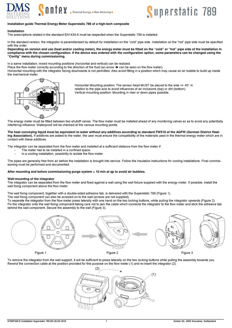
Horizontal Mounting position: The sensor head MUST be placed to the side +/- 45° in
relation to the pipe axis to avoid influences of air inclusions (top) or dirt (bottom).
Vertical mounting position: Mounting in riser or down pipes possible.
0789P300-E Installation Superstatic 789 EN 29-05-2017 2 Sontex SA, 2605 Sonceboz, Switzerland
Mounting of the integrator for a cooling application
Only the flow meter can be fully isolated. Separate the integrator from the flow meter and fix using the wall support aid
It is recommended to separate the integrator from the flow meter and installed at a sufficient distance from the flow meter if:
- The meter has to be installed in a confined space
- The meter is in connection with mounting in condensing environments
- To prolong the battery life time
The pipes are generally free from air before the installation is brought into service. Follow the insulation instructions for cooling installations. Final commis-
sioning must be performed and documented.
After mounting and before commissioning purge system > 10 min at qp to avoid air bubbles.
Wall-mounting of the integrator
The integrator can be separated from the flow meter and fixed against a wall using the wall fixture supplied with the energy meter. If possible, install the
wall fixing component above the flow meter.
The wall fixing component, together with a double-sided adhesive tab, is delivered with the Superstatic 789 (Figure 1).
The wall fixing component can also be screwed on to the wall (screws are not supplied).
To separate the integrator from the flow meter press laterally with one hand on the two locking buttons, while pulling the integrator upwards (Figure 2).
Fix the integrator onto the wall fixing component taking care not to jam the cable which connects the integrator to the flow meter and stick the adhesive tab
behind the wall component. Secure the assembly to the wall (Figure 3).
Figure 1
Figure 2
Figure 3
To remove the integrator from the wall support, it will be sufficient to press laterally on the two locking buttons while pulling the assembly towards you.
Rewind the connection cable at the position provided for this purpose on the flow meter (1) and re-insert the integrator (2).
(1)
(2)
Mounting of the temperature sensors
The temperature sensor in the flow meter has a colourless marking.
The temperature sensor with the orange mark indicates that the sensor must be mounted in the pipe “opposite” to the Superstatic 789.
Example: If the flow meter is installed on the warm side (Hot Pipe), the temperature sensor with the orange mark will be mounted in the cold side (Cold
Pipe).
The Superstatic 789 is delivered with temperature sensors having a cable length of 1.5 m.
The temperature sensors form a sub-assembly with the integrator. The temperature sensor cables must be neither shortened nor lengthened.
The temperatures of use displayed on the label must be respected.
A temperature sensor may be fitted directly in the Superstatic 789 flow meter. The temperature sensors will preferably be fitted directly, in other words one
temperature sensor will be fitted in the flow meter while the other sensor will be installed on the other side of the heat exchanging circuit.
Tighten the nuts of the sensors Ø 5 and Ø 5.2mm with ½ to ¾ turn from the compression of the seal.
When sensor pockets are employed, these must be used specifically for the two temperature sensors and must correspond to the list set out below.
Asymmetrical mounting is also possible. In that case the temperature sensor having a cable marked with orange will be fitted in the other side of the heat
exchanging circuit in a sensor pocket defined according to the table set out below.
To guarantee accuracy in this type of use, the following condition must be respected: at a flow rate < 100 l/h, the temperature difference has to be equal or
larger then 6K, ∆Tmin ≥ 6 K.
Make sure that the sensors are mounted until they stall with the bottom of the sensor pocket.
Sensor pockets list
Temperature sensors
Versions
Pocket
Article number
Material
Temperature range
Ø 5x31 mm
Pt1000
M10x1
0460A212
Brass
0…100 °C
Ø 5x 31 mm
Pt1000
G3/8"
0460A213
Brass
0…100 °C
Ø 5x 31 mm
Pt1000
G1/2"
0460A214
Brass
0…100 °C
Ø 5.2x 31 mm
Pt1000
M10x1
0460A215
Brass
0…100 °C
Ø 5.2x 31 mm
Pt1000
G3/8"
0460A216
Brass
0…100 °C
Ø 5.2x 31 mm
Pt1000
G1/2"
0460A217
Brass
0…100 °C
0789P300-E Installation Superstatic 789 EN 29-05-2017 3 Sontex SA, 2605 Sonceboz, Switzerland
Direct mounting in a T tube
The temperature sensor is on the same level and perpendicular to the pipe axis (DN15, DN20):
Fitting temperature sensors for cooling applications
Insulation shall only be mounted as far as the fixing screw.
The temperature sensor fixing screw must not be covered by any kind of insulation. This likewise applies if the sensor is
fixed directly in the flow meter.
Installation of the Superstatic 789
To install the Superstatic 789, the following steps must be respected :
Flush out the installation pipes carefully in compliance with the DIN/EN standard
specification.
Close the shutoff valves before and behind the meter.
Open the drainage valve to reduce the pressure and discharge the water contained in
the pipe between the two shutoff valves.
Consider the direction of flow circulation. Check the flow direction with the arrow figur-
ing on the flow meter.
Place a gasket on each side of the flow meter. Only use appropriate new gaskets.
Make sure that the gaskets are carefully positioned in relation to the water pipe and
flow meter unions.
Tighten the fixing nuts firmly by hand. Then tighten up using a mounting tool as de-
scribed below.
Install the temperature sensor.
Turn the display into the desired position for reading.
Check the waterproof of the meter placed under pressure.
Seal the flow meter and the temperature sensors.
Precautions to be observed during the mounting :
Between the axis of the pipes an offset (misalignment) of 4mm maximum is tolerated
Use only the EPDM gaskets supplied with the Superstatic 789.
Tightening of the two fixing nuts will be done with a torque wrench with a maximum
tightening torque of:
25 Nm for flow meter qp1,5 m3/h G ¾" (DN15).
50 Nm for flow meters qp1,5 m3/h G 1" (DN20) and qp2,5 m3/h G 1" (DN20).
Mounting distance L1 for the flow meter:
L = 110 mm, qp1,5 m3/h G ¾" (DN15) : L1 = 113 ± 1mm
L = 130 mm, qp1,5 m3/h and qp2,5 m3/h G 1" (DN20) : L1 = 133 ± 1mm
Mounting cable for the pulse input function
The pulse inputs are built with SELV circuits (Safety Extra Low Voltage) and must be only connected with SELV circuits. The electrical characteristics are
displayed on page 8.
Mounting cable for the pulse output function
The pulse outputs are built with SELV circuits (Safety Extra Low Voltage) and must be only connected with SELV circuits. The electrical characteristics are
displayed on page 8.
0789P300-E Installation Superstatic 789 EN 29-05-2017 4 Sontex SA, 2605 Sonceboz, Switzerland
Commissioning from the storage mode
Ex works the flow meter can be in the storage mode, that is to say, it does not count and the display shows "Disabled".
The storage mode is active as long as the meter is not sealed "Seal".
In the storage mode, the transition to "Config" menu is made with a short press on the orange navigation button. Another short press gives access to the
whole sequence of the "Normal" mode.
DISABLED
PUSH
SEAL
Long
pression
Normal
Mode
Automatic
change
CoFG
Short
pression PUSH
Cold.ppe
Pression
longue
PUSH
CHANGE
Long
pression
Automatic
change
000000.01 MWh
Short
pression
PUSH
CHANGE
Long
pression
Automatic
change
000000.01 m3
Short
pression
PUSH
CHANGE
Long
pression
Automatic
change
Short
pression
Cold.ppe
Short
pression 001234.56 MWh
EnergyServiceCounting OFF
Short
pression
//
Short
Pression
In the "Config" menu (optionally available), a long press will change the settings below:
•Flow meter mounting position in the installation. Hot (HOT PIPE) or cold side (COLD PIPE).
•Energy unit (0.1kWh, 1 kWh, 0.001MWh, 0.01MWh, 0.001GJ and 0.01GJ).
•Volume unit (0.01 m3 and 0.001m3).
In the "Config" menu any inaction (i.e. with no pressure on the navigation button) lasting 3 minutes causes the automatic exit and returns to "Disabled". If
changes were made in the "Config" menu, the data remain stored.
Checking operation
Make sure that the measurements indicated by the meter are coherent using the orange button which you will find on the meter. The following values can
be shown on the LCD display: flow, power, hot and cold temperatures. The communication arrows permit display of the controls (inputs) and responses of
the instrument (outputs). All the display parameters will be used to check and adjust the installation. In particular, you must make sure that the
maximum flow rate of the installation does not exceed the maximum flow rate authorised for the meter. To complete the functional analysis, the
commissioning protocol can be saved using the Prog7x9 software via the optical interface.
When "Disabled" is displayed, a long press on the navigation button validates the parameters of the flow meter. The indication
"Seal" flashes four times on the display and it changes to "Normal" counting mode.
From that moment, the storage mode ("Disabled" and "Config") is not accessible anymore.
0789P300-E Installation Superstatic 789 EN 29-05-2017 5 Sontex SA, 2605 Sonceboz, Switzerland
Error codes
The Superstatic 789 integrator displays an error message with the 3 letters “Err” and a code. If several errors occur at the same time, the different codes
are added together.
The error is displayed in the first position of the display menu. It will still be possible to select all the other display menus by pressing the navigation button.
If the navigation button is no longer pressed for a period of 3 minutes, the error code will automatically appear again in the first position of a display menu.
Display of an error automatically disappears when the error is no longer present.
Err 1: Flow higher than 1.2 x qs or defective hydraulic sensor.
Err 2: Measured temperature outside the homologated range or temperature sensor defective.
To make sure that the temperature sensors have not been cross during assembly, the temperature difference between the outward and return tempera-
tures can be checked on the display. Depending on the use (thermal or refrigerating), this temperature difference may be either positive or negative.
Display
The Superstatic 789 LCD display has been designed to be large enough and perfectly readable by the user.
Display sequence
To display general data on the integrator, several windows have been created in the form of menu/sub-menu functions. Depending on the chosen version
of the energy meter, some menus may be added.
The “Energy” window of the main menu is the basic display.
The navigation button enables the user to change from one menu to another and to access the different positions within a menu.
Short pressure on the navigation button permits transition from one menu to another or continuation to the next display while remaining in the same menu.
Long pressure (> 2 seconds) on the navigation button gives access to sub-menu within a menu or enables the “Energy” window to be displayed from within
a menu.
After 3 minutes, the display automatically reverts to the basic “Energy” window.
0789P300-E Installation Superstatic 789 EN 29-05-2017 6 Sontex SA, 2605 Sonceboz, Switzerland
Detailed display sequences in Normal Mode:
MWh001234.56
MWh
001234.56
01
MWh
001234.56
02
MWh
001234.56
03
MWh001234.56
04
MWh001234.56
05
MWh
001234.56
18
Energie
Energie
Energy
Volumen Monat -2
Volume au mois -2
Volume month -2
Letzter Monastwert Volumen
Volume au mois dernier
Last monthly value volume
Volumen Monat -3
Volume au mois -3
Volume month -3
Volumen Monat -4
Volume au mois -4
Volume month -4
Volumen Monat -5
Volume au mois -5
Volume month -5
Volumen Monat -18
Volume au mois -18
Volume month -18
Kumulierte Volumen
Volume cumulé
Cumulated volume
m
3
Volumen
Volume
Volume
001234.56
001234.56
001234.56
001234.56
001234.56
001234.56
01
02
03
04
05
18
m
3
m
3
m
3
m
3
m
3
m
3
001234.56
Datum Stichtag
Jour de relève
Date set day
Energie Stichtag
Energie à la relève
Energy set day
Volumen Stichtag
Volume à la relève
Volume set day
Energie Tariff 1 Stichtag
Energie Tarif 1 à la relève
Energy Tariff 1 set day
Impulseingang 1 Stichtag
Val. Cumul. 1 à la relève
Pulse input 1 set day
Impulseingang 2 Stichtag
Val. Cumul. 2 à la relève
Pulse input 2 set day
29.05.----
S
p
Stichtag
Jour de relève
Set Day
MWh001234.56
001234.56
MWh001234.56
001234.56
001234.56
S
p
S
p
S
p
S
p
S
p
m
3
m
3
m
3
IN2
IN1
Energie Monat -2
Energie au mois -2
Energy month -2
Letzter Monastwert Energie
Energie au mois dernier
Last monthly value energy
Energie Monat -3
Energie au mois -3
Energy month -3
Energie Monat -4
Energie au mois -4
Energy month -4
Energie Monat -5
Energie au mois -5
Energy month -5
Energie Monat -18
Energie au mois -18
Energy month -18
Kumulierte Energie
Energie cumulée
Cumulated energy
Energie Tariff 1 Monat -2
Energie Tariff 1 au mois -2
Energy Tariff 1 month -2
Letzter Monastwert Energie Tariff 1
Energie au mois dernier Tariff 1
Last monthly value energy Tariff 1
Energie Tariff 1 Monat -3
Energie Tariff 1 au mois -3
Energy Tariff 1month -3
Energie Tariff 1 Monat -4
Energie Tariff 1 au mois -4
Energy Tariff 1 month -4
Energie Tariff 1 Monat -5
Energie Tariff 1 au mois -5
Energy Tariff 1 month -5
Energie Tariff 1 Monat -18
Energie Tariff 1 au mois -18
Energy Tariff 1 month -18
Kumulierte Energie Tariff 1
Energie cumuléeTariff 1
Cumulated energy Tariff 1
MWh001234.56
Energie Tariff 1
Energie Tariff 1
Energy tariff 1
MWh001234.56
MWh001234.56
MWh001234.56
MWh001234.56
MWh001234.56
MWh001234.56
01
02
03
04
05
18
Legende
Légende
Legend
Standardanzeige
Position standard
Standard indication
Wird nur angezeigt wenn die Optionverfügbar ist
Affiché seulement si l’option est disponible
Only indicated if the option is available
Wert Monat -2
Valeur au mois -2
Value month -2
Letzter Monastwert
Valeur au mois dernier
Last monthly value
Wert Monat -3
Valeur au mois -3
Value month -3
Wert Monat -4
Valeur au mois -4
Value month -4
Wert Monat -5
Valeur au mois -5
Value month -5
Wert Monat -18
Valeur au mois -18
Value month -18
Kumulierte Wert
Valeur cumulée
Cumulated value
IN1
Zusatzzähler 1
Compteur additionel 1
Additional meter 1
001234.56
001234.56
001234.56
001234.56
001234.56
01
02
03
04
05
m
3
m
3
m
3
m
3
m
3
m
3
IN1
IN1
IN1
IN1
IN1
001234.56
001234.56
18
m
3
IN1
Kurzes Drücken / Pression courte / Short pression on button
Langes Drücken / Pression longue / Long pression on button
Service
34.5°C
23.4°C
K11.14
56.235
kW784.56
14 36
20.01.2012
h12546
m
3
/h
4
4
F
12654321
A886. 43
I
p
68
12654321
COL8.PIPE
1.04
S8FF.
Zusatzzähler 2
Compteur additionel 2
Additional meter 2
IN2
006079.13
006079.13
006079.13
006079.13
006079.13
01
02
03
04
05
m
3
m
3
m
3
m
3
m
3
m
3
IN2
IN2
IN2
IN2
IN2
006079.13
006079.13
18
m
3
IN2
Einbauort Durchflusssensor
Position de montage débitmètre
Flowmeter mounting position
Betriebsstunden
Durée d’utilisation
Running hours
Aktuelle Zeit
Heure actuelle
Time of device
Aktuelles Datum
Date actuelle
Date of device
Hoche Temperatur
Température haute
High temperature
Tiefe Temperatur
Température basse
Low temperature
Temperaturdifferenz
Différence température
Delta temperature
Aktuelle Durchfluss
Débit actuel
Actual flow
Aktuelle Leistung
Puissance actuelle
Actual power
Segmenttest
Test des segments
Test LCD
Identifikationsnummer
Numéro d’identification
Identification number
M-Bus Adresse
Adresse M-Bus
M-Bus address
Radio Adresse
Adresse Radio
Radio address
Firmwareversion
Version Firmware
Firmware Version
0789P300-E Installation Superstatic 789 EN 29-05-2017 7 Sontex SA, 2605 Sonceboz, Switzerland
Communication interface and options
The communication interfaces are installed and pre-set in the factory. When ordering, you must specify the interface type: either remote powered M-Bus or
Radio SONTEX or Wireless M-Bus (OMS) or two pulse outputs.
Pulse input function
The Superstatic 789 offers the possibility of integrating up to two further pulse input from other meters, for instance a hot water and a cold water meter.
The value of the pulse factor is programmable via the Prog7X9 software. By default, the pulse factor will be 1 Pulse/Unit for each pulse input.
The meter data are aggregated separately in totalizers and can be shown on the display as IN1 and IN2; they can also be transferred via the communica-
tion interface which is installed in the integrator. The Superstatic 789 is delivered with a cable length of 1.5 m for the input pulse signals.
Pulse output function
If ordered the Superstatic 789 offers the possibility of integrating two open collectors pulse outputs which can represent hot energy, cold energy or volume.
Energy Meter – heating or cooling application:
- Output S1 = Heating or cooling energy
- Output S2 = Volume
Mixed application heating and cooling:
- Output S1 = Heating energy
- Output S2 = Cooling energy
Whenever the smallest energy unit (hot or/and cold) or volume displayed on the screen is incremented, 1 pulse will be transmitted on the corresponding
output cable S1/S2.
Example for energy:
Display 12345678 kWh ==> output pulse value for energy = 1 kWh / pulse
Display 12345,678 MWh ==> output pulse value for energy = 0.001 MWh / pulse
Display 123456,78 GJ ==> output pulse value for energy = 0.01 GJ / pulse
Example for volume:
Display 12345,678 m3==> output pulse value for volume = 0.001 m3/ pulse
Display 123456,78 m3==> output pulse value for volume = 0.01 m3/ pulse
The Superstatic 789 is supplied with a cable length of 1.5 m for pulse outputs.
Electrical characteristics of the pulse outputs: open collector 1 Hz 500 ms.
Optical interface
The optical interface is available on every Superstatic 789.
Communication between the Prog7X9 software and Superstatic 789 can be done by means of an optical coupler.
The Prog7x9 software is mainly used to configure the non-metrological parameters and for readout.
The transmission speed is set at 2400 bauds and cannot be changed.
We recommend the use of optical couplers supplied by: www.petechnik.de
Should communication problems occur, please refer to the document User Guide Prog7X9 (integrated as PDF in the software).
For the optical probe listed below, we have noted the filters needed to permit correct communication with Prog7X9 software:
Optical probe Filter
P+E Technik : "K1-98" or "K1-06" No filter
P+E Technik : "K01-USB" No filter
SONTEX Radio
The SONTEX Radio communication interface supports communication between all Sontex products having this interface. It must be specified when order-
ing. The radio module will then be installed and configured in the factory.
The SONTEX Radio interfaces make use of a bi-directional radio technology which is a highly reliable and performant solution for a remote metering sys-
tem (fixed or mobile). The technology employed is based on MFD and Radian 0 protocols and works at a frequency of 433.82 MHz.
The products fitted with this Radio module can be accessed 365 days a year from 06:00 to 20:00.
The radio address is displayed in the Service menu if it corresponds to the serial number of the Superstatic 789.
Technical data of the radio communication system:
Bi-directional communication; FSK Modulation; Frequency 433.82 MHz; Radian 0 radio protocol.
The life cycle is calculated for normal metering. Factors such as: the environmental temperature during use, the number of readings taken etc.
influence the battery service life.
Wireless M-Bus Radio
The Wireless M-Bus module is used to transfer data according to the wM-Bus (EN13757-4) radio communication protocol and in compliance with the OMS
(Open Metering System) Release V3.0.1. To have this interface provided in the Superstatic, it is necessary to specify when ordering. The Wireless M-bus
module will be installed and configured at the factory. A specific notice will be added to the standard documentation.
Powered remote M-Bus
The powered remote M-Bus communication interface is a serial interface which permits communication between different M-Bus devices via a central M-
Bus station. It must be specified when ordering. The powered remote M-Bus module will hence be installed and configured in the factory.
By default, the primary address will be configured with the address 0 and the secondary address will correspond to the serial number of the Superstatic
789. To change the value of the secondary address, you must use the Prog7X9 software or send M-Bus specific orders. The secondary address corre-
sponds to the identification field ID. The primary address is displayed in the Service menu with the indication [Addr:].
Technical data for the M-bus communication system:
M-Bus protocol compliant with standard EN 1434-3; free potential interfacing without polarity (the voltage measured on the last device must exceed
36VDC); transmission speed 300/2400 Baud; variable data structure. A M-bus device is seen as two M-Bus charges by the Master.
Type of cable recommended: telephone cable JYStY N*2*0.8 mm2
0789P300-E Installation Superstatic 789 EN 29-05-2017 8 Sontex SA, 2605 Sonceboz, Switzerland
Security seals
As sealing varies from country to country, local regulations must be followed. To protect the system against all unauthorised manipulations, the energy
meter, the connection screws, the temperature sensors and the sensor pockets must all be sealed. The seals may only be removed by authorised persons.
In the event of failure to comply with this instruction, the guarantee obligation will lapse. It is important for the wire seal to be as short as possible so that it
is slightly taut. This is the only way of preventing malicious interference.
A factory seal (2) will be applied to the temperature sensor mounted in flow meter. To mount the temperature sensor on the other side of the installation,
the Sontex seal (S written in black on a grey background). or wire seal supplied with the meter must be used.
The detector support fitted on the flow sensor can’t be removed without being damaged or broken.
Position of the seals:
Seals installed in the factory on flow meter (1) and temperature sensor (2) of the Superstatic 789
Metrological seal applied in the factory on the integrator
2
1
0789P300-E Installation Superstatic 789 EN 29-05-2017 9 Sontex SA, 2605 Sonceboz, Switzerland
Technical data Superstatic 789 of high-tech composite
Flow measurement
qp Threaded
connection
Mounting
length
Mat. PN Maximal
flow
qs
Minimal
flow
qi
Low flow
threshold
value
(50°C)
Threaded
hole for
sensor
Total
Meter
Weight
Kvs
value
(20°C)
Pressure
loss at
qp
m3/h
G"
DN
mm
bar
m3/h
l/h
l/h
kg
m3/h
bar
(EN ISO
228-1)
1.5
3/4"
(15)
110
Comp
16
3
15
10
Yes
0.72
3.4
0.2
1.5 1" (20) 130 Comp 16 3 15 10 Yes 0.74 3.4 0.2
2.5
1"
(20)
130
Comp
16
5
25
17
Yes
0.75
5.6
0.2
Comp = high-tech Composite 16 bar = 1.6 MPa L: Mounting length
The flow sensor Superstatic 789 can be operated from 0,8 bar in the pipe.
Mounting
The Superstatic 789 should not be mounted on the side where the continuous operating temperature of the liquid exceeds 90°C or is below 5°C.
Length of straight section fitted upstream/downstream of each flow meter (EN1434): U3 / D0 for: L=110mm
U0 / D0 for: L=130mm
Temperature sensors
Temperature sensor 2 wires Pt1‘000
Diameter Ø5.0; Ø5.2, Ø6.0 mm
Cables length 1.5 m
Measurement
Approved temperature range 0…110°C
Differential range 3…75 K
Response limit 0.5 K
Temperature resolution (display) 0.1 °C
Temperature resolution ∆t (display) 0.01 K
Temperature-measurement cycle at nominal flow 10 seconds
Flow-measurement cycle Permanent
Integrator General
Environment class C
Mechanics M1
Electronics E1
Battery protection class III
Cable connection between flow sensor and integrator 0.6 m, fix
Integrator Protection index IP 65
Operating temperature 5…55°C
Operating temperature with radio version 5…40°C
Storage and transport temperature -10…60°C
Power supply
Lithium battery 3V 6+1 or 12+1 years
Pulse output
Open drain (MOS Transistor) 1 Hz, 500 ms
Vccmax : 35 VDC ; Iccmax : 25mA
Pulse inputs with a dry contact
Power supply internal 2.3 VDC
Rpull UP internal 2 MΩ
Pulse factor 0...999.999 m3/Imp or without unit
Powered by M-Bus line 1 device = 2 M-Bus charges (max 2 x 1.5mA)
Metrological class EN 1434 class 2
CE conformity according to Directive 2014/32/EU (MID)
RED 2014/53/EU
Type Examination Certificate CH-MI004-13019
Type Examination Certificate (Cooling) DE-16-M-PTB-0084
Technical support
For technical support, please contact your local Sontex agent of Sontex SA directly.
Hotline Sontex: support@sontex.ch, +41 32 488 30 04
Detailed declarations of conformity can be found on our homepage: www.sontex.ch
Modifications subject to change without notice Sontex SA 2015

Other manuals for Superstatic 789

2

This manual suits for next models

2

Other Sontex Measuring Instrument manuals

Sontex Superstatic 789 User manual

Sontex

Sontex Superstatic 789 User manual

Sontex Supercal 739 Manual

Sontex

Sontex Supercal 739 Manual

Sontex Superstatic 470 SPF User manual

Sontex

Sontex Superstatic 470 SPF User manual

Sontex Supercal 5 User manual

Sontex

Sontex Supercal 5 User manual

Sontex Supercal 739 User manual

Sontex

Sontex Supercal 739 User manual

Sontex Supercal 739 User manual

Sontex

Sontex Supercal 739 User manual

Sontex Supercal 531 User manual

Sontex

Sontex Supercal 531 User manual

Sontex Superaqua 1 User manual

Sontex

Sontex Superaqua 1 User manual

Sontex Superstatic 789 User manual

Sontex

Sontex Superstatic 789 User manual

Sontex 56 Series User manual

Sontex

Sontex 56 Series User manual

Sontex Supercal 531 User manual

Sontex

Sontex Supercal 531 User manual

Sontex Superstatic 449 Instruction sheet

Sontex

Sontex Superstatic 449 Instruction sheet

Sontex Supercal 5 I User manual

Sontex

Sontex Supercal 5 I User manual

Sontex Supercal 531 Instruction sheet

Sontex

Sontex Supercal 531 Instruction sheet

Sontex Supercal 739 User manual

Sontex

Sontex Supercal 739 User manual

Sontex Superstatic 749 User manual

Sontex

Sontex Superstatic 749 User manual

Sontex Supercal 5 User manual

Sontex

Sontex Supercal 5 User manual

Sontex Superstatic 440 User manual

Sontex

Sontex Superstatic 440 User manual

Popular Measuring Instrument manuals by other brands

RKC INSTRUMENT LE100 Communication instruction manual

RKC INSTRUMENT

RKC INSTRUMENT LE100 Communication instruction manual

Ryobi E49MM01 Operator's manual

Ryobi

Ryobi E49MM01 Operator's manual

Acrel ARTM-Pn Installation & operation manual

Acrel

Acrel ARTM-Pn Installation & operation manual

Badger Meter Blancett 1100 Series user manual

Badger Meter

Badger Meter Blancett 1100 Series user manual

Leica HDS7000 user manual

Leica

Leica HDS7000 user manual

Siemens SITRANS LG250 operating instructions

Siemens

Siemens SITRANS LG250 operating instructions

Maynuo Electronic M97 series user guide

Maynuo Electronic

Maynuo Electronic M97 series user guide

Flomec D-40 instruction manual

Flomec

Flomec D-40 instruction manual

Hanna Instruments HI 84429 instruction manual

Hanna Instruments

Hanna Instruments HI 84429 instruction manual

ABB FAM3200 Series Commissioning Instruction

ABB

ABB FAM3200 Series Commissioning Instruction

Trotec Bl20 operating manual

Trotec

Trotec Bl20 operating manual

PDi DP-110 Operation manual

PDi

PDi DP-110 Operation manual

agratronix MT-PRO+ Operator's manual

agratronix

agratronix MT-PRO+ Operator's manual

TESTO Smart Probes 510i instruction manual

TESTO

TESTO Smart Probes 510i instruction manual

Vishay P3 instruction manual

Vishay

Vishay P3 instruction manual

Benewake TF02 product manual

Benewake

Benewake TF02 product manual

KEMKRAFT KEI-095A Instructional manual

KEMKRAFT

KEMKRAFT KEI-095A Instructional manual

Oval WaterMaster instructions

Oval

Oval WaterMaster instructions

manuals.online logo
manuals.online logoBrands
  • About & Mission
  • Contact us
  • Privacy Policy
  • Terms and Conditions

Copyright 2025 Manuals.Online. All Rights Reserved.