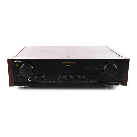
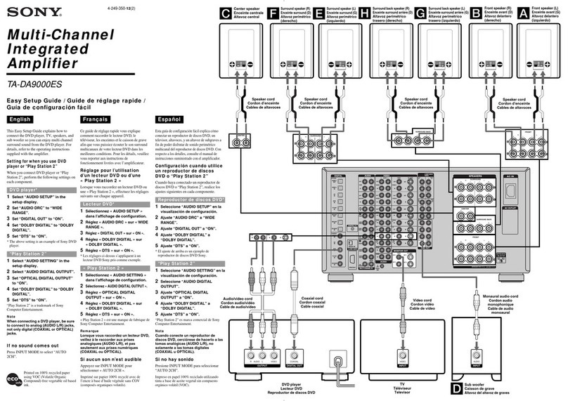
Sony TA-AV411 User manual

SONY
Integrated
Stereo
Amplifier
A-AV411
Operating
Instructions
Before
operating
the
unit,
please
read
this
manual
thoroughly
and
retain
it
for
future
reference.
Owner's
Record
The
model
and
serial
numbers
are
located
at
the
rear.
Record
the
serial
number
in
the
space
provided
below.
Refer
to
them
whenever
you
call
upon
your
Sony
dealer
regarding
this
product.
Model
No.
TA-AV411
To
prevent
fire
or
shock
hazard,
do
not
expose
the
unit
to
rain
or
moisture.
AN
J
CAUTION:
TO
REDUCE
THE
RISK
OF
ELECTRIC
SHOCK,
Serial
No.
OT
NUARIO)S
RISK
OF
ELECTRIC
00
NOT
OPEN
00
NOT
REMOVE
COVER
(OR
BACK).
NO
USER-SERVICEABLE
PARTS
INSIDE.
REFER
SERVICING
TO
QUALIFIED
SERVICE
PERSONNEL.
This
symbol
is
intended
to
alert
the
user
to
the
presence
of
uninsulated
“dangerous
voltage”
within
the
prod-
uct's
enclosure
that
may
be
of
suffi-
cient
magnitude
to
constitute
a
risk
of
electric
shock
to
persons.
This
symbol
is
intended
to
alert
the
user
to
the
presence
of
important
operating
and
maintenance
(servicing)
instructions
in
the
literature
accompa-
nying
the
appliance.
*
The
graphical
symbols
are
on
the
rear
enclosure.
3-753-099-21(2)
Precautions
On
safety
©
Operate
the
unit
only
on
120
V
AC,
60
Hz.
¢
Should
any
solid
object
or
liquid
fall
into
the
unit,
unplug
it
and
have
it
checked
by
qualified
personne!
before
operating
it
any
further.
e
Unplug
the
unit
from
the
wall
outlet
if
it
is
not
to
be
used
for
an
extended
period
of
time.
To
disconnect
the
cord,
pull
it
out
by
grasping
the
plug.
Never
pull
the
cord
itself.
On
installation
©
Place
the
unit
on
a
level
surface.
Do
not
install
the
unit
in
a
location
near
heat
sources
such
as
radiators
or
air
ducts,
or
in
a
place
subject
to
direct
sunlight,
excessive
dust,
mechanical
vibration
or
shock.
©
Good
air
circulation
is
essential
to
prevent
internal
heat
buildup
in
the
unit.
Place
the
unit
in
a
location
with
adequate
air
circulation.
Do
not
piace
the
unit
on
a
soft
surface,
such
as
a
rug
that
would
block
the
ventilation
holes
on
the
bottom.
©
Do
not
place
anything
on
top
of
the
cabinet.
The
top
ventilation
holes
must
be
unobstructed
for
the
proper
operation
of
the
unit
and
to
prolong
the
life
of
its
components.
On
cleaning
the
cabinet
Clean
the
cabinet,
panel
and
controts
with
a
soft
cloth
lightly
moistened
with
mild
detergent
solution.
Do
not
use
any
type
of
abrasive
pad,
scouring
powder
or
solvent
such
as
alcohol
or
benzine.
On
repacking
Do
not
throw
away
the
carton
and
the
packing
material.
It
makes
an
ideal
container
to
transport
the
unit
in.
If
you
have
any
question
or
problem
concerning
your
unit,
please
consult
your
nearest
Sony
dealer.
For
detailed
precautions,
see
the
leaflet
"IMPORTANT
SAFEGUARD".

OFel
al
alsyevaie)
ars
*
Connect
the
AC
power
cord
last.
Make
sure
power
is
off.
¢
Cord
plugs
and
jacks
are
color
coded.
Red
plugs
and
jacks
are
for
right
channel
(R)
and
white
ones
for
the
left
channel
(L).
¢
The
cable
connectors
should
be
fully
inserted
into
the
jacks.
A
loose
connection
may
cause
hum
and
noise.
¢
The
+
and
-
cords
of
the
speaker
systems
should
be
correctly
connected
to
the
+
and
-
terminals
of
the
amplifier
respectively.
The
numbers
described
@
correspond
to
the
individual
Front
speakers
connecting
diagram.
Right
Left
Cassette
deck
an
tat
Turntable
system
a
oe
tae
MS.
nina
tele
=e
=
so|
|
=p
to
LINE
|
to
LINE
=
>
IN
OUT
REAR
SPEAKER
TUNER
IN
‘
FRONT
SPEAKER
VIDEO
IN
A-AV411
PHONO
IN
CONTROL
S
OUT
TAPE
IN
TAPE
REC
OUT
Malte
or
cementite
.:.
esi
dletiatinstns
ame
to
CONTROL
S
IN
to
LINE
OUT
Tuner
to
LINE
OUT
CD
player
a
ates
wltline
Note
on
speaker
impedance
and
power
capacity
To
connect
a
video
tape
recorder
This
amplifier
is
designed
to
work
best
with
speakers
of
Use
the
following
cables.
nominal
impedance
from
8
to
16
ohms.
Be
sure
to
use
a
speaker
system
with
adequate
power
handling
capabilities.
phono
plug
x
2
-
phono
plug
x
2
or
monaural
video
tape
recorder
RK-G105
mini
plug
x
1
-—
phono
plug
x
2
RK-C72
phono
plug
x
1
-
phono
plug
x
2

|
Mroter-hifejame}m
Oxo}
al
ide)
fs
TA-AV4EI1
Gi
system
PowER
switch
When
the
SYSTEM
POWER
switch
is
tumed
ON,
the
Settings
on
the
display
panel
are
automatically
reset
the
EA
MODE
setector
Selects
the
function
mode
on
the
remote
commander.
1:
To
select
the
function
indicated
in
light
gray
such
as
DECK,
DAT,
CD
player
and
surround
mode
of
2:
To
elect
the
functions
indicated
in
bive
such
a8
VIR,
Be
UDP
(Laser
diec
player)
and
TV.
The
combined
CD/LD
player
can
be
controlled
with
LOP
Position.
=
D
(disc)
SKIP:
Disc
skip
(for
a
CD
player
equipped
with
@
muhi-disc
changer)
“44>:
Manual
search
(only
for
LD
player)
44/4
Locates
a
desired
selection.
85
Arapuitier/TV
section
TVMIDEO
button:
Selects
the
input
signal
of
the TV.
(for
TV)
Program
number
(1
to
0)
and
ENTER
buttons.
Select
the
channel.
(for
TV)
SURROUND
mode
selectors
(lor
the
ampiitier)
ON/OFF:
Turns
orvotf
the
surround
mode.
MODE:
Selects
the
surround
mode.
Selectors:
Select
an
input
source
of
the
ampiitier.
FUNCTION
(for
the
ampiifier)
REAR
VOL
/TV VOL
+/-
buttons:
Control
the
volume
of
rear
Speakers
(surround
level)
or
TV.
OBFB
button:
Tums
on/off
the
OBFE
(Dynamic
Bass
Feed
Back)
(for
the
ampiitier)
MASTER
VOL
+/-
buttons:
Control
the
amplifier
volume.
(for
the
amplifier)
G2)
Tunec/TV
section
é
SHIFT
and
TUNER
PRESET/
TV
CH
(channel)
+/-
buttons.
Select
a
preset
channel
of
the
tuner
or
a
channel
of
the
TV.
[18]
Tape
deck/VCR
control
section
DECK/VTR
selector
DECK
A,B,
and
DAT:
Selects
A,B,
or
DAT
deck.
VIR
1,
2,
and
3.
Selects
VCR
type.
(1:
Betamax
VCRs,
2:
8
men
VCRs,
3:
VHS
VCRs)
2
Two
size-AA
(R6)
batteries
<>:
Play
@(REC):
Recording
ANT
(antenna)
TV/VTR
button:
Selects
the
output
signal
from
the
antenna
terminal
on
the
VCR,
either
a
TV
signal
or
VCR
Programs.
VIR
CH
(channel)
+/-
buttons.
Setect
channel
on
the
VCR
Power
control
section
SYSTEM
OFF
button:
Turns
off
the
power
of
the
whole
system.
LOP,
VTR,
TV,
and
AUDIO
Sattery
life
About
hall
a
year
of
normal
operation
can
be
expected
when
using
the
Sony
SUM-3
(NS)
batteries.
When
the
battenes
are
exhausted,
the
remote
commander
can
no
longer
operate
the
unit.
if
thes
happens,
replace
both
balleries
with
new
ones.
To
avoid
battery
leakage
When
the
commander
is
not
be
used
for
a
tong
time,
remove
the
Dalteries
to
avoid
damage
caused
by
batlery
leakage
and
Corrosion.
Adjusting
the
Audio
‘The
following
operations
apply
only
to
reproduced
.
Volume
Adjustment
To
increase
the
sound
level,
turn
the
MASTER
VOLUME
Clockwise.
To
decrease
it
.
tum
the
control
counterclockwise
To
reinforce
bass.
Press
the
DBFB
(Dynamic
Bass
Feedback)
switch
to
ON.
The
lower
the
sound
level
is,
the
more
the
bass
is
emphasized.
To
adjust
tone
quatity
Adjust
the
S-band
stereo
graphic
equalizer
controls
according
to:
©
Personal
preference
©
The
room
acoustics.
For
instance,
playback
in
a
room
with
padded
watts
or
furniture
will
probably
sound
better
with
the
high
i
©
Program
quaiity.
it
r@production
contains
hiss,
Cutting
the
higher
frequencies
will
improve
playback.
Function
of
the
graphic
equalizer
controls
100
Hz:
Boosts
or
cuts
bass.
390
Hz:
Adjusts
the
power,
spaciousness
and
warmth
of
the
sound.
TkHz:
Provides
more
presence
for
vocals.
3.3
kHz:
Boosts
a
brighter
sound
or
reduces
stridency
10
kitz:
Highlights
the
delicate
quality
of
insvumental
sound.
To
change
relative
strength
of
the
right
and
left
speaker
Outputs,
adjust
the
BALANCE
contro!
For
personal
listening
Connect
headphone
to
the
HEADPHONES
jack.
it
howling
occurs
white
listening
to
a
record
Swatch
off
DBFB.
Then turn
down
the
volume
and
slide
down
100
Hz
controls
until
howling
stops.
Howling
occurs
when
the
vibrations
of
the
boosted
bass
are
picked
up
by
the
stylus,
and
reproduced
once
again.

Listening
to
a
Program
Source
wer
‘alate!
a!
Selecting
the
speaker
system
To
drive
speaker
system
A:
Set
SPEAKERS
to
°A’.
To
drive
speaker
system
B:
Set
SPEAKERS
to
°B’.
To
drive
both
speakers:
Set
SPEAKERS
to
‘A
+
8’.
For
headphone
listening
only:
Set
SPEAKERS
to
“OFF.
Notes
*
When
SPEAKERS
is
set
to
°A
+
B’,
two
pairs
of
speaker
presi
aaah
alle
a
Otherwise,
no
sound
can
*
The
sound
of
rear
(surround)
speakers
are
not
heard
from
the
headphone.
atezexe)
welfare]
You
can
record
any
program
source
using
a
tape
deck
connected
to
the
TAPE
jacks.
The
BALANCE,
VOLUME,
GRAPHIC
EQUALIZER
controls
and
the
DBFB
switch
have
no
effect
on
recording.
field
bal
ial)
Serer
fall
:
a
2
Select
the
speaker
system
Selecting
the
program
source
For
a
record
program,
press
PHONO
For
a
tuner
program,
press
TUNER
For
a
CD
program,
press
CD.
For
a
tape
program,
press
TAPE.
For
a
video
sound
program,
press
VIDEO.
1
select
the
program
source
other
than
TAPE
So)
heel
3
set
the
tape deck
in
the
fecording
mode.
2
Play
the
program
source
3
Select
the
program
source
Stay
(obalare
mole
lacolelate
stele
late!
The
surround
sound
wil
be
effective
when
surround
speakers
(optional)
are
connected
to
the
REAR
SPEAKER
panel.
=
5S
=,
lata
at
oe
|
lo
Gane
LL
ta
ey
—
Selecting
surround
modes
DOLBY®
(Dolby
Surround)
Fa
ee
ee
en
DA
nants
Renter.
HALL
(Halt
Surround)
Lag
en
eeneeomr
ann
anect
Wal
is
piocaicedd
8
8
concest
SIMULATED
(Simulated
Surround)
Gives
a
simulate
stereo effect
to
monaural
sound.
Turns
on
and
off the
surround
mode.
*
Manulactured
under
license
from
Dolby
Laboratories
Licensing
Corporation
Additionally
licensed
U.S
numbers
3.632.886,
3.746.792
and
3,959,590,
Caneckan
numbers
1.004.603
and
1,037,877.
“DOLBY”
and
the
double-D
symbo!
00
are
trademarks
of
Dolby
Laboratories
ies
Licensing
Corporabon.
1
Select
the
surround
mode
Note
No
sound
will
be
heard
from
the
surround
speakers,
unless
One
of
the
Surround
modes
is
selected.
Adjusting
the
INPUT
BALANCE
contro!
In
the
DOLBY
SURROUND
mode
adjust
this
control
so
that
the
(audio)
volume
of
the
surround
speaker
is
minimized
Guring
the
scene
of
conversation
(where
the
sound
is
monaural).
under
one
of
more
of
the
following
petents:
ety
a

@
Front
speakers
@
Rear
speakers
You
can
connect
two
pairs
of
speaker
systems:
Connect
a
pair
of
rear
speaker
systems
for
enjoying
system
A
and
system
B.
surround
sound.
They
can
be
selected
individually
or
simultaneously
with
the
selector
on
the
front
panel.
@
Flat
remote
control
cord
(not
supplied)
Connect
to
the
CONTROL
S
IN
jack
of
other
Sony
equipment
with
the
flat
remote
control
cord
for
whole
audio
system
remote
control.
Push
in
until
it
clicks.
To
disconnect.
@
AC
OUTLETs
(SWITCHED)
@
Power
cord
Use
these
to
power
audio
components
whose
power
Connect
to
a
wail
outlet.
consumption
is
less
than
the
wattage
indicated
on
the
AC
outlets.
These
outlets
are
controlled
by
the
POWER
switch.
CAUTION
Do
not
connect
any
electrical
home
appliances
such
as
an
electric
iron,
fan,
TV
or
other
high
wattage
equipment
to
these
AC
outlets.

Bitelelol(-s-islolelerare,
Before
going
through
the
check
list
below,
first
refer
back
to
the
connection
and
operating
procedures.
Should
any
problem
persist
after
you
have
made
these
checks,
consult
your
nearest
Sony
dealer.
No
audio.
No
audio
from
one
channel.
Lack
of
bass
sound
or
obscure
instrument
position.
Severe
hum
or
noise
when
using
the
turntable.
Noise
when
TV
is
turned
on.
Switching
on
DBFB
does
not
affect
the
sound.
Specifications
AUDIO
POWER
SPECIFICATIONS
POWER
OUTPUT
AND
TOTAL
HARMONIC
DISTORTION:
With
8-ohm
loads,
both
channels
driven,
from
40
-
20,000
Hz;
rated
135
watts
per
channel
minimum
RMS
power,
with
fess
than
0.9%
total
harmonic
distortion
from
250
milliwatts
to
rated
output.
Ampiifier
section
Power
bandwidth
(IHF)
30
Hz
-
30
KHz
(8
ohms)
1.7
dB
(‘78
IHF)
Less
than
0.9%
at
rated
output
(Surround
OFF)
PHONO:
RIAA
equalization
curve
CD,
VIDEO,
TUNER,
TAPE:
30
Hz
-
30
kHz
+3dB
15
W
+
15
W(8
ohms)
27
(8
ohms,
1
kHz)
Dynamic
headroom
Harmonic
distortion
Frequency
response
Surround
output
Damping
factor
Input
Jack
S/N
(weighting
roe
[Sey
[rae
71
dB
(A,
3.0
mV)
'
92
dB
Phono
}250mV
j|50kohms
1/83
dB*
(A,
250
mV)
Sony
Corporation
Printed
in
Malaysia
CD,VIDEO
TUNER,
TAPE
“78
IHF
e@
Check
the
power
cord
connection.
@
Check
the
SPEAKERS
selector
setting.
e
Check
the
connections.
e
Check
the
setting
of
the
function
selector.
e
Check
the
speaker
terminal
connection
and
the
speaker
cord
for
a
short.
e
Adjust
the
BALANCE
control.
e
Check
the
speaker
cord
or
connecting
cord
connection.
e
Check
the
connection
between
the
amplifier
and
speakers.
e
Ground
the
turntable
system.
e
Fully
insert
the
plug
of
the
connecting
cord.
e
Disconnect
the
ground
wire
of
the
turntable
from
the
terminal
when
using
an
MM
cartridge
with
a
ground
piece.
e
Move
the
TV
away
from
the
audio
system.
e
DBFB
reinforces
only
low
frequencies.
Output
TAPE
Phono
jacks
Voltage
150
mV
(REC
OUT)
impedance
1
kohm
SPEAKERS
Accepts
speakers
of
8
-
16
ohms
HEADPHONES
|
Stereophone
|
Accepts
low
and
high
jack
impedance
headphones.
GRAPHIC
EQUALIZER
controls
Boost/Cut
range:
£8
dB
(100
Hz,
330
Hz,
1
kHz,
3.3
kHz)
+6
dB
(10
kHz)
General
Power
requirements
120
V
AC,
60
Hz
Power
consumption
AC
outlets
3
switched,
120
W/1
A
max.
Dimensions
Approx.
430
x
145
x
360
mm
(w/h/d)
(17
x
5S5/_
x
14g
inches)
Weight
Approx.
9.9
kg
(21
Ib
14
02)
Accessories
supplied
Remote
Commander
RM-U212
(1)
Sony
batteries
SUM
3(NS}
(2)
Design
and
specifications
subject
to
change
without
notice.
Other manuals for TA-AV411
2
Table of contents
Other Sony Amplifier manuals

Sony
Sony XM-ZR604 - AMPLIFIER 4 CHANNEL User manual

Sony
Sony TA-VE800G User manual

Sony
Sony XM-GTX6020 User manual

Sony
Sony TA-F501ES User manual

Sony
Sony XM-DS1300P5 Operating & Mounting User manual

Sony
Sony TA-AV661 User manual

Sony
Sony TA-SB500WR2 User manual

Sony
Sony XM-GTX6040 - Stereo Power Amplifier User manual

Sony
Sony TA-FB920R User manual

Sony
Sony TA-A1ES User manual