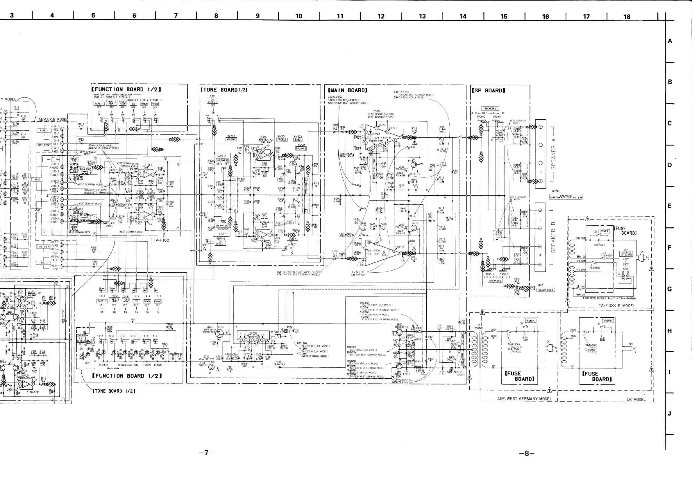
Sony TA-F100 User manual
Other Sony Amplifier manuals

Sony
Sony TA-FE910R User manual

Sony
Sony XM-N1004 User manual

Sony
Sony XM-1600GSD Marketing Specifications,... User manual

Sony
Sony TA-F3000 User manual

Sony
Sony TA-FE600R User manual

Sony
Sony TA-F5000 User manual

Sony
Sony XM-GTX6040 - Stereo Power Amplifier User manual

Sony
Sony TA-FB940R User manual

Sony
Sony XM-2200GTX Operating & Mounting User manual

Sony
Sony TAD-M30 User manual

Sony
Sony TA-FB940R User manual

Sony
Sony PHA-3 Guide

Sony
Sony TA-FA777ES User manual

Sony
Sony TA-N80ES User manual

Sony
Sony TA-WR4 User manual

Sony
Sony TA-N1 User manual

Sony
Sony TA-E1 Operating Instructions (primary... User manual

Sony
Sony TA-VA777ES User manual

Sony
Sony XM-GS6DSP User manual

Sony
Sony TA-V606 User manual