General
System
Power
requirements
Power
consumption
Dimensions
Mass
Supplied
accessories
Preamplifier:
Low-noise,
equalizer
amplifier
Power
amplifier:
Pure-complementary
SEPP
OCL
power
amplifier
with
all
stages
directly
coupled
220
V
-
230
V
AC,
50/60
Hz
Model
for
Scandinavian
countries,
Switzerland,
Spain
and
Portugal
TA-F645R:
180
W
TA-F545R:
140
W
Model
for
other
countries
TA-F645R:
260
W
TA-F545R:
200
W
Approx.
430
x
135
x
375
mm
(w/h/d)
(17x
53/,
x
147/,
inches)
TA-F645R:
Approx.
9.4
kg
(20
Ib
12
oz)
TA-F545R:
Approx.
8.5
kg
(18
Ib
12
oz)
Remote
commander
RM-S311
(1)
Sony
SUM-3
(NS)
batteries
(2)
The
above
values
are
measured
at
230
V
AC.
Design
and
specifications
are
subject
to
change
without
notice.
Note
This
appliance
conforms
with
EEC
Directive
87/308/EEC
regarding
interference
suppression.
TABLE
OF
CONTENTS
Section
Title
Ts
“GENERAL
Adecco
Aah
Mel
aes
aA
aye
Jaen
2.
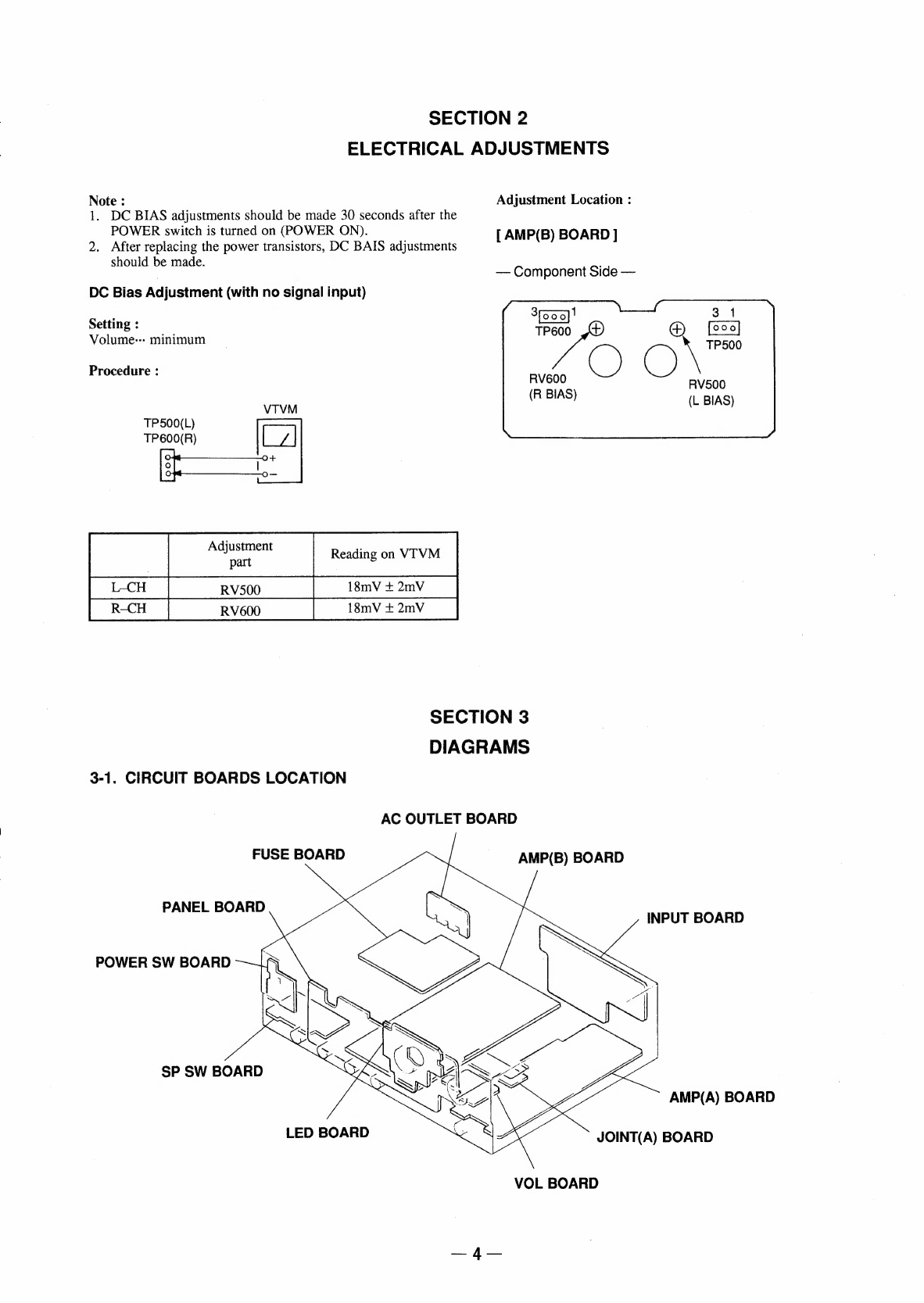
ELECTRICAL
ADJUSTMENTS
.............ccccc
eee
3.
DIAGRAMS
3-1.
Circuit
Boards
Location
oo...
eceeccssesessceccccccececesasseueees
Soe.
-BIOCK
DIAQI
AI
2sciciccdascccsassensterteey
vented
acs
atacaetasshenen
ase
3-3.
IC
Pin
Functions
*
10701
TMP74C200BN-H307..........cccccsssssecseserssessssersens
3-4.
Semiconductor
Lead
Layouts
..........ccccccssesesecssesssneveseens
3-5.
Printed
Wiring
Boards
—
Panel
Section
—
............00
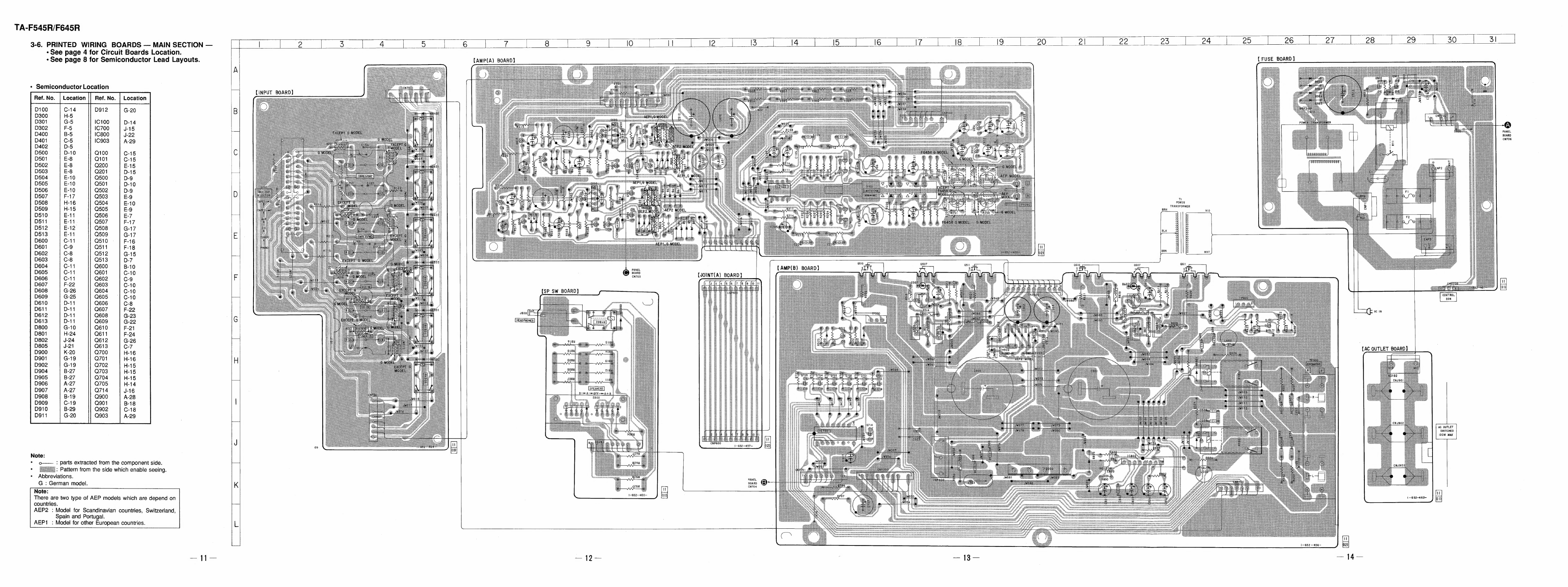
3-6.
Printed
Wiring
Boards
—
Main
Section
—
.......
3-7.
Schematic
Diagram
—
Panel/
Main
Section
—
...........
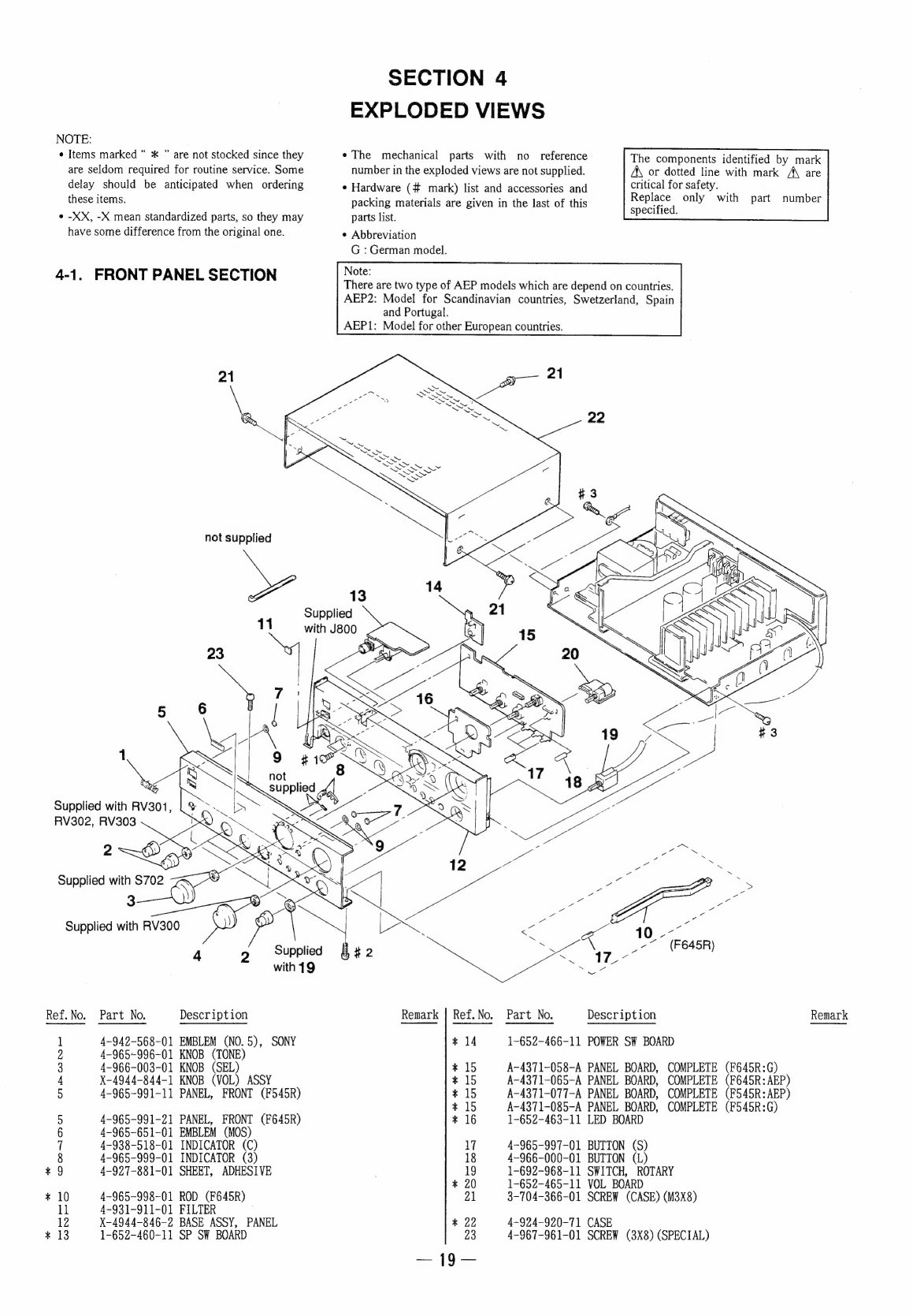
4.
EXPLODED
VIEW
4-1.
Front
Panel
Section
oo.
ccceecesssececesssscscesesessesecssenss
4-2.
Back
Panel
Section
ooo.
ceecccccsccscccceccessscscscsccescesseseeesenuees
4-3.
Chassis
S@CtION
oo...
eee
ccc
cceesccecsccccccscscscsssacssacssestenseraceares
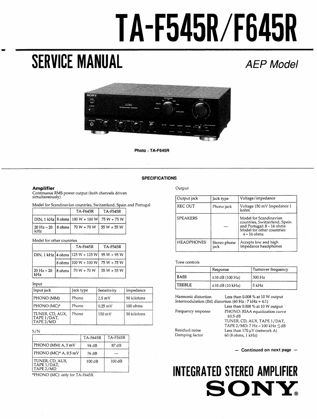
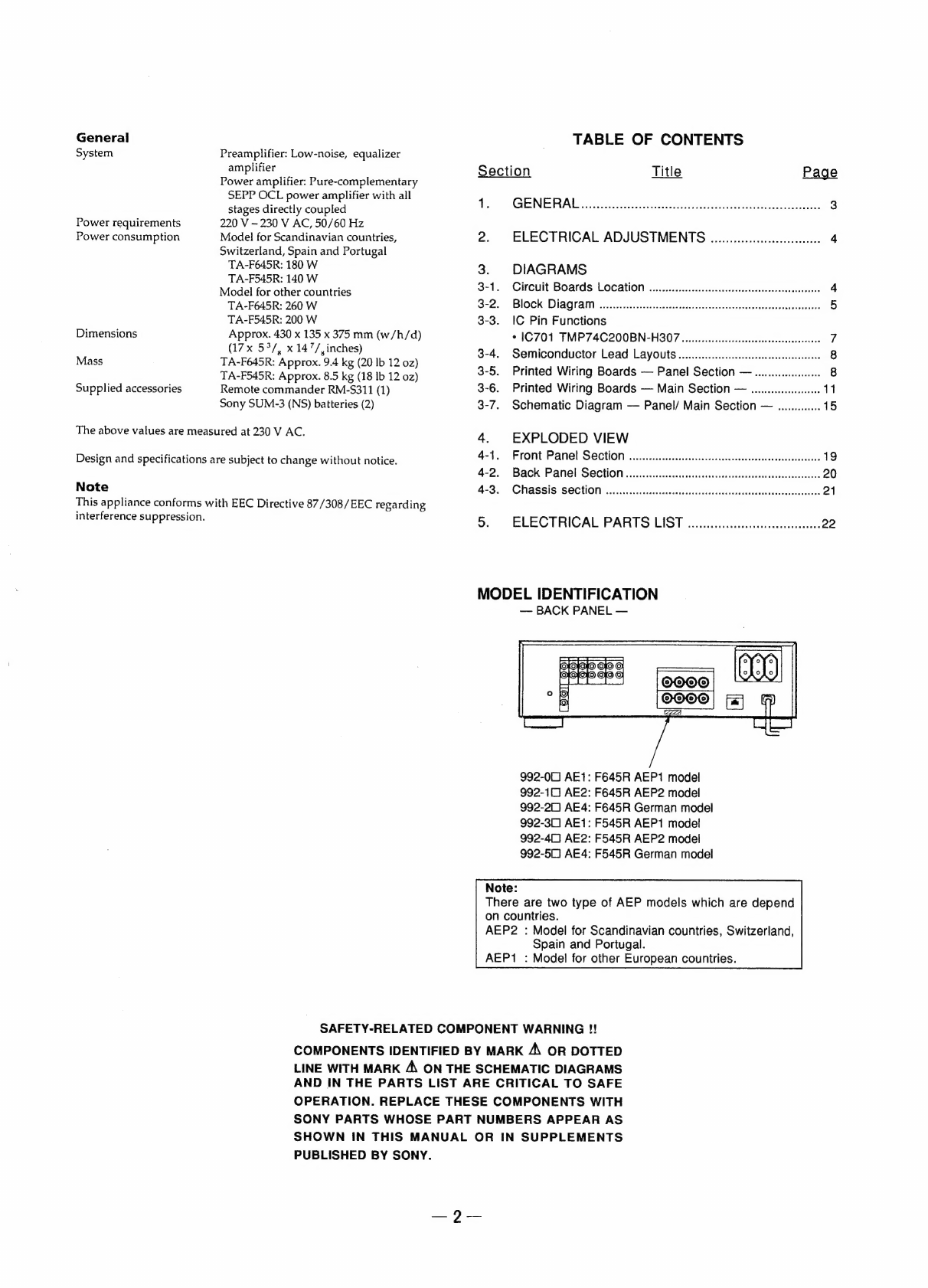
MODEL
IDENTIFICATION
—
BACK
PANEL
—
992-00)
AE1:
F645R
AEP1
model
992-11)
AE2:
F645R
AEP2
model
992-21)
AE4:
F645R
German
model
992-3C0)
AE1:
F545R
AEP1
model
992-40)
AE2:
F545R
AEP2
model
992-50]
AE4:
F545R
German
model
Note:
There
are
two
type
of
AEP
models
which
are
depend
on
countries.
AEP2
:
Model
for
Scandinavian
countries,
Switzerland,
Spain
and
Portugal.
AEP1
:
Model
for
other
European
countries.
SAFETY-RELATED
COMPONENT
WARNING
!!
COMPONENTS
IDENTIFIED
BY
MARK
A\
OR
DOTTED
LINE
WITH
MARK
A\
ON
THE
SCHEMATIC
DIAGRAMS
AND
IN
THE
PARTS
LIST
ARE
CRITICAL
TO
SAFE
OPERATION.
REPLACE
THESE
COMPONENTS
WITH
SONY
PARTS
WHOSE
PART
NUMBERS
APPEAR
AS
SHOWN
IN
THIS
MANUAL
OR
IN
SUPPLEMENTS
PUBLISHED
BY
SONY.
—2—