manuals.online logo
Brands
  1. Home
  2. •
  3. Brands
  4. •
  5. Sony
  6. •
  7. Camera Accessories
  8. •
  9. Sony SEL-1018 User manual

Sony SEL-1018 User manual

Other manuals for SEL-1018

1

Other Sony Camera Accessories manuals

Sony Cyber-shot Station CSS-PC1 User manual

Sony

Sony Cyber-shot Station CSS-PC1 User manual

Sony HDVF-9900 User manual

Sony

Sony HDVF-9900 User manual

Sony DSC-W7/B User manual

Sony

Sony DSC-W7/B User manual

Sony HVL-F43M Installation and operation manual

Sony

Sony HVL-F43M Installation and operation manual

Sony HDLA1500 User manual

Sony

Sony HDLA1500 User manual

Sony MPK-P1 User manual

Sony

Sony MPK-P1 User manual

Sony MPK-WEB User manual

Sony

Sony MPK-WEB User manual

Sony SPK-HCG User manual

Sony

Sony SPK-HCG User manual

Sony CA-570 User manual

Sony

Sony CA-570 User manual

Sony VCT-D480RM User manual

Sony

Sony VCT-D480RM User manual

Sony CCU-M5A User manual

Sony

Sony CCU-M5A User manual

Sony VF-62CPK User manual

Sony

Sony VF-62CPK User manual

Sony DXF-51 User manual

Sony

Sony DXF-51 User manual

Sony LA-EA2 User manual

Sony

Sony LA-EA2 User manual

Sony FCB-EX78BP User manual

Sony

Sony FCB-EX78BP User manual

Sony LA-EA5 User manual

Sony

Sony LA-EA5 User manual

Sony XCST70 User manual

Sony

Sony XCST70 User manual

Sony SMAD-P5 User manual

Sony

Sony SMAD-P5 User manual

Sony MPK-THHB User manual

Sony

Sony MPK-THHB User manual

Sony CCU-700A User manual

Sony

Sony CCU-700A User manual

Sony LC-HD7 User manual

Sony

Sony LC-HD7 User manual

Sony HDCU-3300R User manual

Sony

Sony HDCU-3300R User manual

Sony CCU-TX50 User manual

Sony

Sony CCU-TX50 User manual

Sony HVL-20DW2 User manual

Sony

Sony HVL-20DW2 User manual

Popular Camera Accessories manuals by other brands

CamRanger CamRanger user manual

CamRanger

CamRanger CamRanger user manual

Custom Brackets HDV CAGE KIT Instructions for use

Custom Brackets

Custom Brackets HDV CAGE KIT Instructions for use

Aegis ABL052010P user manual

Aegis

Aegis ABL052010P user manual

Saft SRA Series Installation and operating instructions

Saft

Saft SRA Series Installation and operating instructions

Kodak TIB5200 technical information

Kodak

Kodak TIB5200 technical information

Videotec HEG instruction manual

Videotec

Videotec HEG instruction manual

Ikelite 6171.11 manual

Ikelite

Ikelite 6171.11 manual

Pentax Auto Bellows Slide Copier K user manual

Pentax

Pentax Auto Bellows Slide Copier K user manual

Nikon UT-1 user manual

Nikon

Nikon UT-1 user manual

dji RONIN 4D quick start guide

dji

dji RONIN 4D quick start guide

SLIK ABLE 300DX user manual

SLIK

SLIK ABLE 300DX user manual

Rebelcell 36V70 user manual

Rebelcell

Rebelcell 36V70 user manual

Trojan GC2 48V quick start guide

Trojan

Trojan GC2 48V quick start guide

Calumet 7100 Series CK7114 operating instructions

Calumet

Calumet 7100 Series CK7114 operating instructions

Ropox 4Single Series User manual and installation instructions

Ropox

Ropox 4Single Series User manual and installation instructions

Cambo Wide DS Digital Series Main operating instructions

Cambo

Cambo Wide DS Digital Series Main operating instructions

Samsung SHG-120 Specification sheet

Samsung

Samsung SHG-120 Specification sheet

Ryobi BPL-1820 Owner's operating manual

Ryobi

Ryobi BPL-1820 Owner's operating manual

manuals.online logo
manuals.online logoBrands
  • About & Mission
  • Contact us
  • Privacy Policy
  • Terms and Conditions

Copyright 2025 Manuals.Online. All Rights Reserved.

Sony Corporation
Revision History
SERVICE MANUAL
Link (English)
SPECIFICATIONS DISASSEMBLY SERVICE NOTE
REPAIR PARTS LIST ADJUSTMENTS
Link (Japanese)
SPECIFICATIONS DISASSEMBLY SERVICE NOTE
REPAIR PARTS LIST ADJUSTMENTS
SEL1018 (E 4/10-18 OSS) (E 10-18mm F4 OSS)
983470513.pdf
2017C08-1
© 2017.03
Published by Sony Techno Create Corporation
INTERCHANGEABLE LENS
9-834-705-13
Ver. Date History Contents S.M. Rev.
issued
1.0 2012.11 Official Release — —
1.1 2016.12 Revised-1
(A1 16-079)
• Change of DISASSEMBLY.
English: Page
2-2, 2-5
Japanese: Page 2-2, 2-5
• Addition of DISASSEMBLY.
English: Page 2-3, 2-6
Japanese: Page 2-3, 2-6
• Change of REPAIR PARTS LIST.
Page 3-1, 3-2
• Addition of Section 4. ADJUSTMENTS.
English: Page 4-1
Japanese: Page 4-1
Yes
1.2 2017.03 Revised-2
(A2 15-173)
• Revision of ADJUSTMENTS.
English: Page
4-1
Japanese: Page 4-1
Yes
SEL1018
(E 4/10-18 OSS) (E 10-18mm F4 OSS)
Ver. 1.2 2017.03 US Model
Canadian Model
AEP Model
Chinese Model
Japanese Model
分解図につきましては,英語版を
ご参照下さい。
Revision History
Revised-2
Replace the previously issued
SERVICE MANUAL 9-834-705-12
with this Manual.
– 2 –
SEL1018 (E 4/10-18 OSS) (E 10-18mm F4 OSS)
– ENGLISH – – JAPANESE –
SPECIFICATIONS
• This lens is equipped with a distance encoder. The distance encoder allows more accurate measurement (ADI) by employing a flash for the process.
• Depending on the lens mechanism, the focal length may change with any change of the shooting distance. The focal length assumes the lens is
focused at infinity.
Equivalent 35mm-format focal length*1(mm)
15-27
Lens groups-elements
8-10
Angle of view*1
109°-76°
Minimum focus*2(m (feet))
0.25 (0.82)
Maximum magnification (X)
0.1
Minimum f-stop
f/22
Filter diameter (mm)
62
Dimensions (maximum diameter ×height) (approx., mm (in.))
70.0×63.5 (2 7/8×2 1/2)
Mass (approx., g (oz))
225 (8)
Shake compensation function
Yes
*1 The values shown above for equivalent 35mm-format focal length and angle of view are for Interchangeable Lens Cameras equipped with an
APS-C sized image sensor.
*2 Minimum focus is the shortest distance from the image sensor to the subject.
• Depending on the lens mechanism, the focal length may change with any change in shooting distance. The focal lengths given above assume the lens
is focused at infinity.
Included items
Lens (1), Front lens cap (1), Rear lens cap (1), Lens hood (1), Set of printed documentation
Design and specifications are subject to change without notice.
is a trademark of Sony Corporation.
概略仕様
・ このレンズは距離エンコーダーを搭載しています。距離エンコーダーにより、高精度な調光(ADI調光)をADI対応フラッシュとの組
み合わせで実現しています。
・ レンズの機構によっては、撮影距離の変化に伴って焦点距離が変化する場合があります。記載の焦点距離は撮影距離が無限遠での
定義です。
35mm判換算焦点距離*1(mm)
 15-27
レンズ群一枚
 8-10
画角*1
 109°-76°
最短撮影距離*2
(m)
 0.25
最大撮影倍率(倍)
 0.1
最小絞り
 F22
フィルター径(mm)
62
外形寸法(最大径×長さ)(約:mm)
 70.0×63.5
質量(約:g)
 225
手ブレ補正機能
あり
*1 ここでの35mm判換算焦点距離と画角は、APS-Cサイズ相当の撮像素子を搭載したレンズ交換式デジタルカメラでの値を表しま
す。
*2 最短撮影距離とは、撮像素子面から被写体までの最短距離を表します。
•レンズの機構によっては、撮影距離の変化に伴って焦点距離が変化する場合があります。記載の焦点距離は撮影距離が無限遠での
定義です。
同梱物
 レンズ(1)、レンズフロントキャップ(1)、レンズリヤキャップ(1)、レンズフード(1)、印刷物一式
仕様および外観は、改良のため予告なく変更することがありますが、ご了承ください。
はソニー株式会社の商標です。
SEL1018 (E 4/10-18 OSS) (E 10-18mm F4 OSS)
1-1
1. SERVICE NOTE
1-1. Chemicals
Some chemicals used for servicing are highly volatile.
Their evaporation caused by improper management affects your health and environment, and wastes resources.
Manage the chemicals carefully as follows.
• Store chemicals sealed in a specific place to prevent from exposure to high temperature or direct sunlight.
• Avoid dividing chemicals into excessive numbers of small containers to reduce natural evaporation.
• Keep containers sealed to avoid natural evaporation when chemicals are not in use.
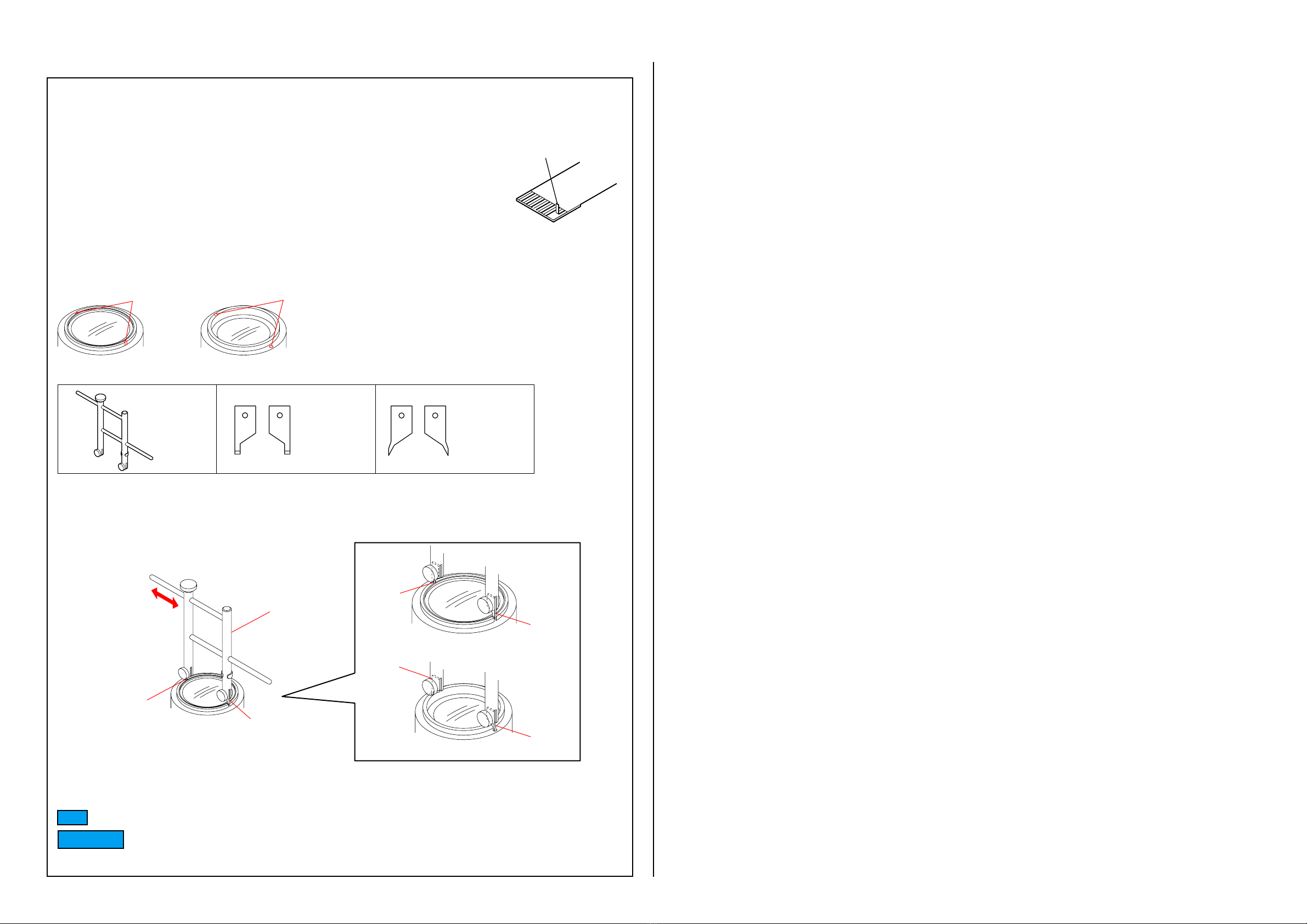
• Avoid using chemicals as much as possible. When using chemicals, divide only required amount to a small plate from the container and
use up it.
1-2. Exterior Parts
Be careful to the following points for exterior parts used in this unit.
• Use a piece of cleaning paper or cleaning cloth for cleaning exterior parts. Avoid using chemicals.
Even if you have to use chemicals to clean heavy dirt, donʼt use paint thinner, ketone, nor alcohol.
• Insert the specific screws vertically to the part when installing a exterior part.
Be careful not to tighten screws too much.
1-3. Unleaded Solder
This unit uses unleaded solder.
Boards requiring use of unleaded solder are printed with the lead free mark (LF) indicating the solder contains no lead.
(Caution: Some printed circuit boards may not come printed with the lead free mark due to their particular size.)
: LEAD FREE MARK
Be careful to the following points to solder or unsolder.
• Set the soldering iron tip temperature to 350 C approximately.
If cannot control temperature, solder/unsolder at high temperature for a short time.
Caution: The printed pattern (copper foil) may peel away if the heated tip is applied for too long, so be careful!
Unleaded solder is more viscous (sticky, less prone to flow) than ordinary solder so use caution not to let solder bridges occur such as on
IC pins, etc.
• Be sure to control soldering iron tips used for unleaded solder and those for leaded solder so they are managed separately. Mixing un-
leaded solder and leaded solder will cause detachment phenomenon.
1-4. SAFETY CHECK-OUT
After correcting the original service problem, perform the following safety checks before releasing the set to the customer.
1. Check the area of your repair for unsoldered or poorly-soldered connections. Check the entire board surface for solder splashes and
bridges.
2. Check the interboard wiring to ensure that no wires are “pinched”or contact high-wattage resistors.
3. Look for unauthorized replacement parts, particularly transistors, that were installed during a previous repair. Point them out to the
customer and recommend their replacement.
4. Look for parts which, through functioning, show obvious signs of deterioration. Point them out to the customer and recommend their
replacement.
5. Check the B+ voltage to see it is at the values specified.
6. Flexible Circuit Board Repairing
• Set the soldering iron tip temperature to 350 C approximately.
• Do not touch the soldering iron on the same conductor of the circuit board (within 3 times).
• Be careful not to apply force on the conductor when soldering or unsoldering.
Caution
Danger of explosion if battery is incorrectly replaced.
Replace only with the same or equivalent type.
Dispose of used batteries according to the instructions.
SAFETY-RELATED COMPONENT WARNING!!
COMPONENTS IDENTIFIED BY MARK 0OR DOTTED LINE
WITH MARK 0ON THE SCHEMATIC DIAGRAMS AND IN
THE PARTS LIST ARE CRITICAL TO SAFE OPERATION.
REPLACE THESE COMPONENTS WITH SONY PARTS
WHOSE PART NUMBERS APPEAR AS SHOWN IN THIS
MANUAL OR IN SUPPLEMENTS PUBLISHED BY SONY.
ATTENTION AU COMPOSANT AYANT RAPPORT
À LA SÉCURITÉ!
LES COMPOSANTS IDENTIFÉS PAR UNE MARQUE
0SUR LES DIAGRAMMES SCHÉMATIQUES ET LA
LISTE DES PIÈCES SONT CRITIQUES POUR LA
SÉCURITÉ DE FONCTIONNEMENT. NE REMPLACER CES
COMPOSANTS QUE PAR DES PIÈSES SONY DONT LES
NUMÉROS SONT DONNÉS DANS CE MANUEL OU DANS
LES SUPPÉMENTS PUBLIÉS PAR SONY.
1-5. NOTE ON REPLACEMENT OF OPTICS UNIT FOR SERVICE
To replace the Optics Unit For Service, connect the E-mount lens to the NEX-3/5/C3, and release the specified flag in the following proce-
dure.
• Implement [Service Flag OFF (S)] of E-Mount Lens Adjustment (Adjustment Application for Service) for SEL18200.
Note: The lens cannot be detected when the E-mount lens is connected to the NEX-3/5/C3 without releasing the specified flag.
Displayed as “F--”
– ENGLISH –
2-1
SEL1018 (E 4/10-18 OSS) (E 10-18mm F4 OSS)
2. DISASSEMBLY
NOTE FOR REPAIR
• Make sure that the flat cable and flexible board are not cracked of bent at the terminal.
Do not insert the cable insufficiently nor crookedly.
• When remove a connector, donʼt pull at wire of connector. It is possible that a wire is snapped.
• When installing a connector, donʼt press down at wire of connector.
It is possible that a wire is snapped.
• Do not apply excessive load to the gilded flexible board.
Notches Holes
How to Use
Universal wrench
J-6082-609-A
Chip-A for
universal wrench:
J-6082-609-1
Chip-B for
universal wrench:
J-6082-609-2
A
ttach the chip-A or chip-B to the universal wrench.
For the notches:
For the holes:
UNIVERSAL WRENCH
In case of the following notches or holes are located in the lens block, etc. during disassembling/
assembling the lens, Use the universal wrench.
chip-A
chip-B
Notches
Holes
Chip
Chip-A
Chip-A
Chip-B
Chip-B
Chip
Match the universal wrench to the holes or notches of the lens block, etc.
Match the universal wrench
to the width of holes or notches.
Universal wrench
LOCTITE 460 or
the equivalent LOCTITE 460 or
the equivalent
SERVICE TOOLS
B-110
Bond (B-110) J-6082-617-
A
Cut and remove the part of gilt
which comes off at the point.
(Be careful or some
pieces of gilt may be left inside)
2-2
SEL1018 (E 4/10-18 OSS) (E 10-18mm F4 OSS)
2-1. DISASSEMBLY-1
When the Fixed Tube Section is removed, the Optical block may be disassembled.
Be careful not to be disassemble the Optical block.
(Note) Notes for Removing the Fixed Tube Section.
(Note)
B-110
LOCTITE 460 or
the equivalent
qf
qd
qg
F
E
D
C
D
E
F
C
1
2
3
4
5
6
7
8
Ornamental Plate
F Lock Pin
Front Tube Assy
Focus Ring Assy
Zoom Ring Assy
Rear Tube Assy
CL-1002 Board
PC Board Rubber Damper
Vibration-Proofing Sheet
FB Washer
GP Mount
Rear Tube
Contact Block Assy
Stopper Screw
Fixed Tube Block
PI Fixed Plate
Adhesive Tape
Filter Screw Frame
(See Page 2-3)
qa
qs
9
HELP03
HELP02
HELP01
q;
HELP04
HELP05
(Note)
The changed portions from
Ver. 1.0 are shown in blue.
Ver. 1.1 2016.12
2-3
SEL1018 (E 4/10-18 OSS) (E 10-18mm F4 OSS)
2-2. DISASSEMBLY-2
2 Group Service Assy
4 Group Mask
Cam Tube
Straight Tube
Vibration Proof Service Assy
1 Group Assy
1
HELP06
3
HELP08
HELP07
2
Ver. 1.1 2016.12
2-4
HELP
Note for assembling and grease applying positions are shown.
SEL1018 (E 4/10-18 OSS) (E 10-18mm F4 OSS)
HELP01
Make folding lines on the flexible board of Contact Block Assy at where is shown below.
Mountain fold
Contact Block Assy
Valley fold
HELP02
1. Install the Zoom Ring Assy, aligning the entrance part of groove B with the zoom potentio lever, and aligning the two Cam Tube
Coma Screws with the two grooves of the Zoom Ring Assy (inside).
2. Check operation of the Zoom Ring Assy.
Zoom Ring Assy
Zoom Ring Assy (inside)
Entrance part of groove B
Groove
Groove
Zoom potentio lever
Cam Tube Coma Screw
Cam Tube Coma Screw
HELP03
Adhesive bond (B-110): J-6082-617-A
1. Assemble Front Tube Assy by fitting the phases at the three places of Bayonet and fitting the direction of the mounting hole of the F
lock pin.
2. Turn Front Tube Assy in the direction indicated by the arrow, and fit it with the inserting hole of the F lock pin.
3. Install the F Lock Pin.
4. Apply the adhesive bond (B-110) to the indicated portion.
Apply the adhesive
bond (B-110)
F Lock Pin
FLockPin
Bayonet
Front Tube Assy
2-5
SEL1018 (E 4/10-18 OSS) (E 10-18mm F4 OSS)
HELP04
1. Affix the to Adhesive Tapes to the Filter Screw Frame.
2. Install Ornamental Plate, aligning the cutout of the ornamental plate (back side) with the projection of the Filter Screw Frame.
Filter Screw Frame
Filter Screw FrameOrnamental Plate (back side)
Cutout Projection
Ornamental Plate
Adhesive Tapes
Adhesive Tapes
HELP05
Install the Filter Screw Frame, aligning the projection of the Filter Screw Frame (back side) with cutout of the optical block,
and then tighten three screws.
Filter Screw Frame
Optical Block
Optical Block
Filter Screw Frame (back side)
Cutout
Projection
Ver. 1.1 2016.12
HELP06
1. Match the groove of 2 Group Service Assy to the Coma of 1 Group Assy and assemble them.
2. Rotate the 1 Group Assy to the fully counterclockwise direction.
Groove
Coma
2 Group Service Assy
1 Group Assy
3. Attach the each flexible board to each groove.
Groove
Flexible Board Flexible Board
HELP07
1. Match the groove of Cam Tube to the Projection of Straight Tube and assemble them. (three places)
2. Rotate the Cam Tube to the fully clockwise direction.
Grooves
Projections
Cam Tube
Straight Tube
2-6
SEL1018 (E 4/10-18 OSS) (E 10-18mm F4 OSS)
3. Match the groove of Straight Tube to the Projection of 2 Group Service Assy and assemble them. (three places)
4. Rotate the Straight Tube to the fully counterclockwise direction.
Straight Tube
Grooves
2 Group Service Assy
Projections
HELP08
1. Pass the flexible board of Vibration Proof Service Assy through the hole of 2 Group Service Assy.
2. Tighten the three screws.
Hole
Flexible Board
2 Group Service Assy
Vibration Proof Service Assy
Ver. 1.1 2016.12
3-1
DISASSEMBLY
(ENGLISH)
DISASSEMBLY
(JAPANESE)
DISASSEMBLY
(ENGLISH)
DISASSEMBLY
(JAPANESE)
SEL1018 (E 4/10-18 OSS) (E 10-18mm F4 OSS)
16
17
16
10
13
ns
ns
22
15
19 19
21
19
19
9
4
4
1
2
11
18
14
12
3
5
8
A
F
G
E
D
C
A
G
C
Optical Block Section
(See section 3-1-2.)
6
7
7
7
7
20
20
7
D
E
F
3. REPAIR PARTS LIST
NOTE:
• -XX and -X mean standardized parts, so they may have some differ-
ence from the original one.
• Items marked
“*”are not stocked since they are seldom required for
routine service. Some delay should be anticipated when ordering these
items.
• The mechanical parts with no reference number in the exploded views
are not supplied.
3-1. EXPLODED VIEWS
3-1-1.OVERALL SECTION
ns: not supplied
Ref. No. Part No. Description Ref. No. Part No. Description
1 4-430-324-01 OPTICS UNIT (AB013) FOR SERVICE
2 X-2582-781-1 A FRONT CAP S (DIA.62)
3 4-447-421-01 (102) ORNAMENTAL PLATE
4 4-447-423-01 (188) ADHESIVE TAPE
5 4-159-676-01 F LOCK PIN
6 4-451-557-01 (101) FILTER SCREW FRAME
7 2-699-027-01 BT2P1.7X5C3C
8 4-451-665-01 (A09) FRONT TUBE ASSY
9 4-451-666-01 (A10) FOCUS RING ASSY
10 4-292-414-01 (113) PLATE, PI FIXED
11 4-451-667-01 (A11) ZOOM RING ASSY
12 4-451-668-01 (A12) REAR TUBE ASSY
13 4-409-954-01 SCREW, GP MOUNT + STOPPER
14 4-208-815-01 BT1P2X4C3C
15 4-209-146-01 CONTACT BLOCK ASSY, (A44)
16 4-292-410-01 2P1.4X2.2B3C
17 4-447-422-01 (402) REAR TUBE
18 4-159-701-03 REAR LENS CAP
19 4-261-330-01 RUBBER (B), PC BOARD DAMPER
20 4-458-532-01 (157)SCREW FOR CAM TUBE
21 4-455-924-01 (213) VIBRATION-PROOFING SHEET
22 4-688-929-01 MAIN PC BOARD ASSY (FW )
The changed portions from
Ver. 1.0 are shown in blue.
Ver. 1.1 2016.12
3-1-2.OPTICAL BLOCK SECTION
ns: not supplied
54
54
53
52
51
55
ns
ns
Ref. No. Part No. Description
51 4-688-926-01 GROUP ASSY, (A02) 1
52 4-688-927-01 SERVICE ASSY, VIBRATION PROOF
53 4-688-928-01 SERVICE ASSY, 2 GROUP
54 2-699-027-01 BT2P1.7X5C3C
55 4-688-930-01 MASK, 4 GROUP