– 3 –
TABLE OF CONTENTS
Section Title Page Section Title Page
Service Note ............................................................................ 4
1. GENERAL
Getting Started .............................................................. 1-3
Hookups ........................................................................ 1-3
Playing Discs ................................................................. 1-6
Searching for a Scene................................................... 1-8
Viewing Information About the Disc .............................. 1-9
Sound Adjustments ....................................................... 1-10
Enjoying Movies ............................................................ 1-10
Using Various Additional Functions .............................. 1-11
Settings and Adjustments ............................................. 1-13
Additional Information ................................................... 1-14
2. DISASSEMBLY
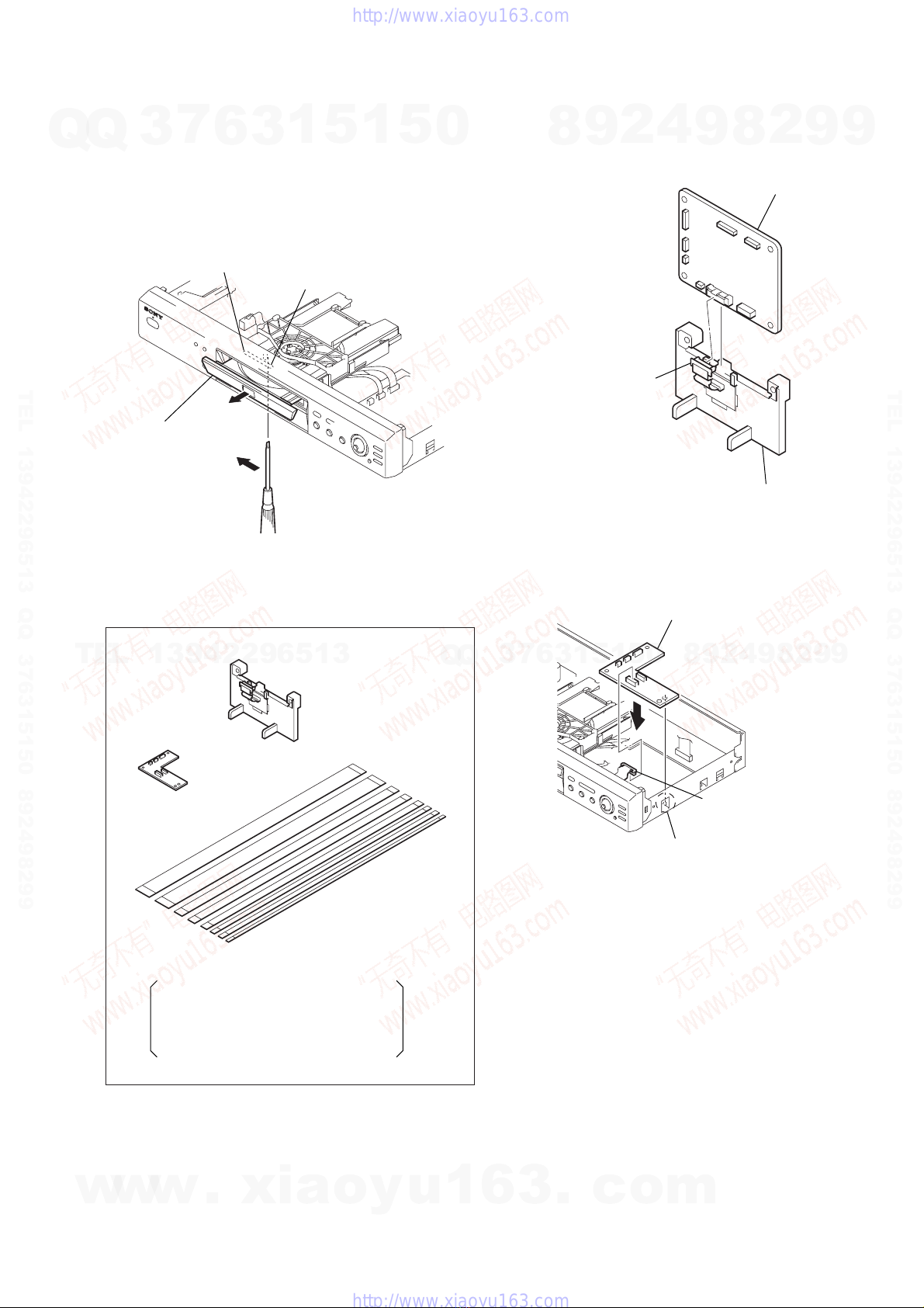
2-1. Case Removal ............................................................... 2-1
2-2. MB-98 Board Removal .................................................. 2-1
2-3. ER-14 Board Removal (AEP, UK, RUS) ....................... 2-1
2-4. Rear Panel Removal ..................................................... 2-1
2-5. AV-56 Board Removal ................................................... 2-2
2-6. Tray Cover Removal ...................................................... 2-2
2-7. Front Panel Removal..................................................... 2-2
2-8. Power Block Removal ................................................... 2-2
2-9. Mechanism Deck Removal............................................ 2-3
2-10. Tray Removal................................................................. 2-3
2-11. Loading Motor (M001), MS-81 Board Removal............ 2-3
2-12. Optical Pick-up Removal ............................................... 2-3
2-13. IF-80 Board Removal .................................................... 2-4
2-14. Internal Views ................................................................ 2-5
2-15. Circuit Boards Location ................................................. 2-6
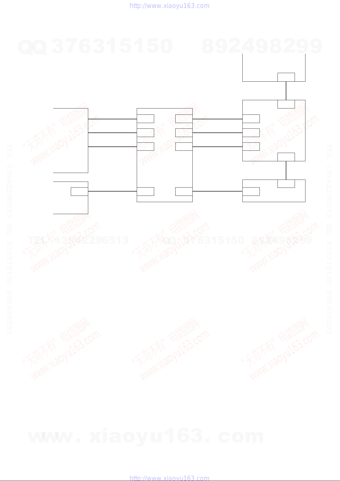
3. BLOCK DIAGRAMS
3-1. Overall Block Diagram................................................... 3-1
3-2. RF/Servo Block Diagram............................................... 3-3
3-3. Signal Processor Block Diagram .................................. 3-5
3-4. System Control Block Diagram ..................................... 3-7
3-5. Video Block Diagram..................................................... 3-9
3-6. Audio Block Diagram..................................................... 3-11
3-7. Interface Control Block Diagram ................................... 3-13
3-8. Power 1 Block Diagram ................................................. 3-15
3-9. Power 2 Block Diagram ................................................. 3-17
3-10. Power 3 Block Diagram ................................................. 3-19
4. PRINTED WIRING BOARDS AND SCHEMATIC
DIAGRAMS
4-1. Frame Schematic Diagram............................................ 4-3
4-2. Printed Wiring Boards and Schematic Diagrams ......... 4-5
MS-81 (LOADING) Printed Wiring Board and
Schematic Diagram ....................................................... 4-5
MB-98 Printed Wiring Board ......................................... 4-7
MB-98 (RF AMP, SERVO) Schematic Diagram ............ 4-11
MB-98 (ARP, SERVO DSP) Schematic Diagram.......... 4-13
MB-98 (AV DECODER) Schematic Diagram................ 4-15
MB-98 (BNR) Schematic Diagram ................................ 4-17
MB-98 (DRIVE) Schematic Diagram ............................ 4-19
MB-98 (SYSTEM CONTROL)
Schematic Diagram ....................................................... 4-21
MB-98 (CLOCK GENERATOR)
Schematic Diagram ....................................................... 4-23
MB-98 (AUDIO DSP, D/A CONVERTER)
Schematic Diagram ....................................................... 4-25
AV-56 Printed Wiring Board .......................................... 4-29
AV-56 (VIDEO BUFFER) Schematic Diagram.............. 4-31
AV-56 (AUDIO AMP) Schematic Diagram .................... 4-33
IF-80 Printed Wiring Board ........................................... 4-35
IF-80 (IF CON) Schematic Diagram ............................. 4-37
ER-14 Printed Wiring Board (AEP, UK, RUS)............... 4-39
ER-14 (EURO AV) Schematic Diagram
(AEP, UK, RUS) ............................................................. 4-41
HS13S0E Printed Wiring Board (AEP, UK, AR, AUS,
E12, EA, HK, KR, ME, RUS, SP) .................................. 4-43
HS13S0E Schematic Diagram (AEP, UK, AR, AUS,
E12, EA, HK, KR, ME, RUS, SP) .................................. 4-45
HS13S0F Printed Wiring Board (BR, E32, PX) ............ 4-47
HS13S0F Schematic Diagram (BR, E32, PX) .............. 4-49
HS13S0U Printed Wiring Board (US, CND, MX, TW) .. 4-51
HS13S0U Schematic Diagram (US, CND, MX, TW) .... 4-53
TOP-244U Printed Wiring Board (US, CND, MX) ......... 4-55
TOP-244U Schematic Diagram (US, CND, MX)........... 4-57
5. IC PIN FUNCTION DESCRIPTION
5-1. System Control Pin Function
(MB-98 Board IC103) .................................................... 5-1
6. TEST MODE
6-1. General Description ...................................................... 6-1
6-2. Starting Test Mode ........................................................ 6-1
6-3. Syscon Diagnosis.......................................................... 6-1
6-4. Drive Auto Adjustment .................................................. 6-5
6-5. Drive Manual Operation ................................................ 6-7
6-6. Mecha Aging ................................................................. 6-10
6-7. Emergency History........................................................ 6-10
6-8. Version Information ....................................................... 6-11
6-9. Video Level Adjustment ................................................ 6-11
6-10. IF CON Self Diagnostic Function.................................. 6-11
6-11. Troubleshooting ............................................................. 6-18
7. ELECTRICAL ADJUSTMENT
7-1. Power Supply Check ..................................................... 7-1
1. HS13S0E/HS13S0F/HS13S0U/TOP-244U Boards...... 7-1
7-2. Adjustment of Video System......................................... 7-2
1. Video Level Adjustment ................................................ 7-2
2. Checking S Video Output S-Y....................................... 7-2
3. Checking S Video Output S-C....................................... 7-2
4. Checking Component Video Output Y .......................... 7-2
5. Checking Component Video Output B-Y ...................... 7-3
6. Checking Component Video Output R-Y ...................... 7-3
7. Checking RGB Output R ............................................... 7-3
8. Checking RGB Output G............................................... 7-3
9. Checking RGB Output B ............................................... 7-4
7-3. Adjustment Related Parts Arrangement ....................... 7-6
8. REPAIR PARTS LIST
8-1. Exploded Views ............................................................. 8-1
8-1-1. Case Assembly ........................................................ 8-1
8-1-2. Chassis Assembly .................................................... 8-3
8-1-3. Mechanism Deck Assembly ..................................... 8-5
8-2. Electrical Parts List ....................................................... 8-6
• Abbreviation
AR : Argentina
AUS :Australian
BR :Brazilian
CND : Canadian
E12 : 220-240 V AC Area in E
E32 : 110-240 V AC Area in E
EA :Saudi Arabia
HK :Hong Kong
KR :Korea
ME : Middle East
MX :Mexican
RUS : Russian
SP : Singapore
TW :Taiwan
w
w
w
.
x
i
a
o
y
u
1
6
3
.
c
o
m
Q
Q
3
7
6
3
1
5
1
5
0
9
9
2
8
9
4
2
9
8
T
E
L
1
3
9
4
2
2
9
6
5
1
3
9
9
2
8
9
4
2
9
8
0
5
1
5
1
3
6
7
3
Q
Q
TEL 13942296513 QQ 376315150 892498299
TEL 13942296513 QQ 376315150 892498299
http://www.xiaoyu163.com
http://www.xiaoyu163.com