SERVICE MANUAL
Sony CONFIDENTIAL
For Authorized Servicer
WH-1000XM3
SPECIFICATIONS
WIRELESS NOISE CANCELING STEREO HEADSET
US Model
Canadian Model
AEP Model
UK Model
E Model
Australian Model
Chinese Model
Tourist Model
Ver. 1.1 2018.10
Except CH: CH:
Communication specification
Communication system:
Bluetooth Specification version 4.2
Output:
Bluetooth Specification Power Class 2
Maximum communication range:
Line of sight approx. 10 m (30 ft)1)
Frequency band:
2.4 GHz band (2.4000 GHz - 2.4835 GHz)
Compatible Bluetooth profiles2):
A2DP (Advanced Audio Distribution Profile)
AVRCP (Audio Video Remote Control Profile)
HFP (Hands-free Profile)
HSP (Headset Profile)
Supported Codec3):
SBC4)
AAC5)
LDAC™
Qualcomm® aptX™ audio
aptX HD
Supported content protection method:
SCMS-T
Transmission range (A2DP):
20 Hz - 40,000 Hz (Sampling frequency LDAC 96 kHz, 990
kbps)
1) The actual range will vary depending on factors such as
obstacles between devices, magnetic fields around a microwave
oven, static electricity, reception sensitivity, antenna’s
performance, operating system, software application, etc.
2) Bluetooth standard profiles indicate the purpose of Bluetooth
communications between devices.
3) Codec: Audio signal compression and conversion format
4) Subband Codec
5) Advanced Audio Coding
Design and specifications are subject to change without notice.
System requirements for battery
charge using USB
USB AC adaptor
A commercially available USB AC adaptor capable of supplying an
output current of 1.5 A or more
Personal Computer
(As of August 2018)
Personal computer with pre-installed with any of the following
operating systems and USB port:
Operating Systems:
When using Windows
Windows® 10 Home / Windows® 10 Pro
Windows® 8.1 / Windows® 8.1 Pro
Windows® 8 / Windows® 8 Pro
Windows® 7
Home Basic / Home Premium / Professional / Ultimate
When using Mac
macOS (version 10.10 or later)
Compatible iPhone/iPod models
iPhone X
iPhone 8
iPhone 8 Plus
iPhone 7
iPhone 7 Plus
iPhone SE
iPhone 6s
iPhone 6s Plus
iPhone 6
iPhone 6 Plus
iPhone 5s
iPod touch (6th generation)
(As of August 2018)
Wireless Noise Canceling Stereo
Headset
Power source:
DC 3.7 V: Built-in lithium-ion rechargeable battery
DC 5 V: When charged using USB
Operating temperature:
0 °C to 40 °C (32 °F to 104 °F)
Rated power consumption:
8 W
Usage hours:
When connecting via the Bluetooth device
Music playback time: Max. 30 hours (NC ON), Max. 22 hours
(Ambient Sound Mode), Max. 38 hours (NC OFF)
Communication time: Max. 24 hours (NC ON), Max.
Standby time: Max. 30 hours (NC ON), Max. 22 hours
(Ambient Sound Mode), Max. 200 hours (NC OFF)
When connecting via the headphone cable with NC ON: Max.
36 hours
Note: Usage hours may be shorter depending on the Codec
and the conditions of use.
Charging time:
Approx. 3 hours
(About 5 hours of music playback is possible after 10 minutes
charging.)
Note: Charging and usage hours may be dierent depending
on the conditions of use.
Charging temperature:
Mass:
Approx. 255 g (8.99 oz)
Receiver
Typ e:
Closed, dynamic
Driver unit:
40 mm (1 5/8 in.)
Impedance:
47 Ω (1 kHz) (when connecting via the headphone cable with
the unit turned on)
16 Ω (1 kHz) (when connecting via the headphone cable with
the unit turned o)
Sensitivity:
104 dB/mW (when connecting via the headphone cable with
the unit turned on)
101 dB/mW (when connecting via the headphone cable with
the unit turned o)
Frequency response:
4 Hz - 40,000 Hz (JEITA)
Microphone
Typ e:
MEMS
Directivity:
Omni directional
18 hours (Ambient Sound Mode), Max. 30 hours (NC OFF)
5 °C to 35 °C (41 °F ~ 95 °F)
Eective frequency range:
50 Hz - 8,000 Hz
Included items:
Wireless Noise Canceling Stereo Headset (1)
USB Type-C™ cable (USB-A to USB-C™) (approx. 20 cm
Headphone cable (approx. 1.2 m (47 1/4 in.)) (1)
Carrying case (1)
Plug adaptor for airplane (1)1)
1) Depending on the in-flight entertainment services, it may not be
supported.
(7 7/8 in.)) (1)
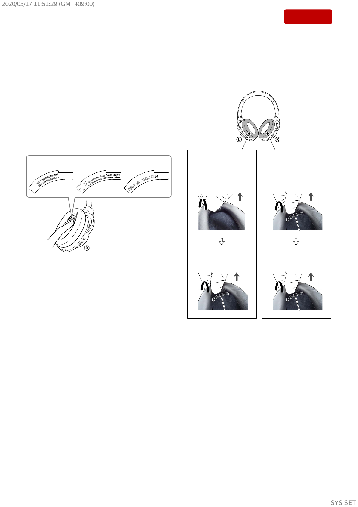
Operating frequency: (AEP, UK)
Bluetooth: 2,400 MHz - 2,483.5 MHz
NFC: 13.56 MHz
Maximum output power: (AEP, UK)
Bluetooth: < 4 dBm
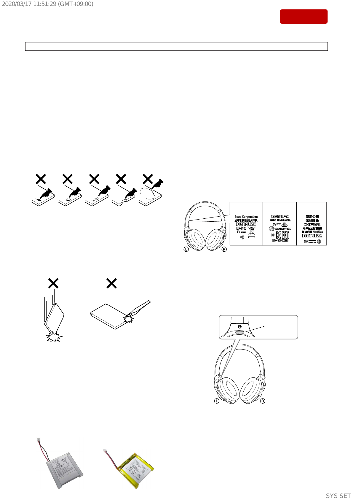
㕄丣斱◎䨯ặ⡔侗㚞
䒙㷴濕
䙘㲥4/8!W濕仒摦䤟⪴₩䒙䒙㯄
䙘㲥6!W濕ợ䒌VTC₩䒙㕚
ⵉỀ㶍⸊濕
1!D兗51!D
栁⫾∃佻濕
9!X
ợ䒌㕚敘濕
彾弫Cmvfuppui嬢⡫彂㌉㕚
杗ᶴ㐑㒢㕚敘濕㙤擣41⭳㕚濃ODㆷ濄濇
㙤擣33⭳㕚濃䌓⟧⡔㦅濄濇㙤擣49⭳㕚
濃OD救濄
彾嬓㕚敘濕㙤擣35⭳㕚濃ODㆷ濄濇㙤擣
29⭳㕚濃䌓⟧⡔㦅濄濇㙤擣41⭳㕚濃OD
救濄
⻩㚞㕚敘濕㙤擣41⭳㕚濃ODㆷ濄濇㙤擣
33⭳㕚濃䌓⟧⡔㦅濄濇㙤擣311⭳㕚
濃OD救濄
ODㆷ㚃敘彾弫侗㚞彂㌉丣彂㌉㕚濕㙤擣47
⭳㕚
㱌び濕太乺奇䝥◌⏰ợ䒌〩ℙ佰⫾濇ợ䒌㕚
敘⍓偡Ṿ亍䝑Ɂ
₩䒙㕚敘濕
上4⭳㕚
濃₩䒙21Ⅺ搃⍲⍓㐑㒢杗ᶴ上6⭳㕚Ɂ濄
㱌び濕₩䒙㕚敘⏰ợ䒌㕚敘⍓偡♄ợ䒌〩ℙ
佰Ɂ
₩䒙㶍⸊濕
6!D兗46!D
岌愳濕
上366!h
㌉㒚◌
䯟⛯濕
⭥救濇∌⽥
槕∌⊹₧濕
51!nn
斟ㇻ濕
58!Ω濃2!lI{濄濃㚐㚞ㆷ㚃敘彾弫侗㚞彂
㌉丣彂㌉㕚濄
27!Ω濃2!lI{濄濃㚐㚞救㚃敘彾弫侗㚞彂
㌉丣彂㌉㕚濄
㿙㒳⸊濕
215!eC0nX濃㚐㚞ㆷ㚃敘彾弫侗㚞彂㌉丣
彂㌉㕚濄
212!eC0nX濃㚐㚞救㚃敘彾弫侗㚞彂㌉丣
彂㌉㕚濄
柵䋫ⷸ濕
5!I{!.!51111!I{濃KFJUB濄
渊₯栲
䯟⛯濕
NFNT
㉫⍵⾋濕
㉫⍵
㙭㒬柵䋫剧♘濕
61!I{!.!9111!I{
≩堩䇍␥濕
㕄丣斱◎䨯ặ⡔侗㚞濃2濄
VTC!Uzqf.D™!彂㌉丣濃VTC.B兗VTC.D™濄!
濃上31!dn濄濃2濄
侗㚞彂㌉丣濃上2/3!n濄濃2濄
ἣ㎞䘶濃2濄
㚞ᵮᵷ䒌㌶⢘彦悱◌濃2濄2*
2*!
太㚞ᵮ⦕ᶴ㙱∅佰⫾濇⍓偡ᵱ⌻㒓㉥Ɂ
孛≣㌶
㚐㌶⢘彦悱◌嬢嬅ᶞ⚌桂㚞ᵮợ䒌Ɂ孛≣⭪
彂㌉↔䒙㷴㌶⸋Ɂ
彾嬓夨㞠
彾嬓䱟乃濕
Cmvfuppui夨㞠䆬㚐5/3
廷⅞濕
Cmvfuppui夨㞠∃䋫䪭下3
㙤⢋彾嬓剧♘濕
太丣上21!n2*
柵䋫㱆㬙;
3/5!HI{㱆㬙濃3/5111!HI{!.!3/5946!HI{濄
柵䋫剧♘濕
3511!NI{!.!3594/6!NI{
⌵⭨∃䋫濕
≤!31!eCn濃FJSQ濄
⬝䗨Cmvfuppui悱仒⊳嬒3*濕
B3EQ濃樼下杗柵Ⅺ悱悱仒⊳嬒濄
BWSDQ濃杗柵太柵彀䥯㌋↚悱仒⊳嬒濄
IGQ濃₱㌴悱仒⊳嬒濄
ITQ濃侗㚞悱仒⊳嬒濄
㒓㉥䗨乺奇䝥◌4*濕
TCD5*
BBD6*
MEBD™
Rvbmdpnn®!bquY™!bvejp
bquY!IE
㒓㉥䗨⬝ὁ㈈㔝㰹濕
TDNT.U
Ẅ廷剧♘濃B3EQ濄濕
31!I{!.!51111!I{濃愫㞛柵䋫MEBD!:7!
lI{濇::1!lcqt濄
2*!
⬂斩剧♘⭪♄嬢⡫敘䗨昀䟱䇍ɀ⼒㱆㿭⏌♘䗨
䠥⚞ɀ暽䒙ɀ㌉㒚㿙㒳⸊ɀ⢍丣⾋偡ɀ㐱Ề䱟
乃ɀ廓Ṛⷸ䒌䥯ⷳ䪭♄䲄佰Ɂ
3*!
Cmvfuppui㝫K悱仒⊳嬒㉫䢞嬢⡫ᶯ敘䗨
Cmvfuppui彾嬓䙒䗨Ɂ
4*!
乺奇䝥◌濕杗柵ὅ⍛⋯亍⏰廐㋆㞠
5*!
⪴ⶊ乺奇䝥◌
6*!
樼下杗柵乺䝥
嬢嬅⏰夨㞠⣦㙭⌼㙘濇⾹ᵱ⍊垰彾䝉Ɂ
ợ䒌VTCᶞ䒙㯄₩䒙䗨䱟乃壥㮦
VTCḈ㲥䒙㷴彦悱◌
偡⢃ỿⷸ2/6!Bㅺ㙘樼廷⅞䒙㲥䗨ⵦ⒒VTCḈ㲥
䒙㷴彦悱◌
ᶎḞ䒙偵
濃ㆎ兗3129ⷘ9㙬濄
柨堩ṉᵯṟび㐱Ề䱟乃ᵸ悱⡫VTC䩓⍇䗨ᶎḞ䒙
偵濕!
㐱Ề䱟乃濕!
ợ䒌Xjoepxt㕚
Xjoepxt®!21!Ipnf!0!Xjoepxt®!21!Qsp
Xjoepxt®!9/2!0!Xjoepxt®!9/2!Qsp
Xjoepxt®!9!0!Xjoepxt®!9!Qsp
Xjoepxt®!8
Ipnf!Cbtjd!0!Ipnf!Qsfnjvn!0!!
Qspgfttjpobm!0!Vmujnbuf
ợ䒌Nbd㕚
nbdPT濃21/21ㅺ㙘㔔䆬㚐濄
⬝jQipof0jQpe㚞⛯
jQipof!Y
jQipof!9
jQipof!9!Qmvt
jQipof!8
jQipof!8!Qmvt
jQipof!TF
jQipof!7t
jQipof!7t!Qmvt
jQipof!7
jQipof!7!Qmvt
jQipof!6t
jQpe!upvdi濃䪐7ṇ濄
濃ㆎ兗3129ⷘ9㙬濄
SYSSET
2020/03/1711:51:29(GMT+09:00)
 User manual")