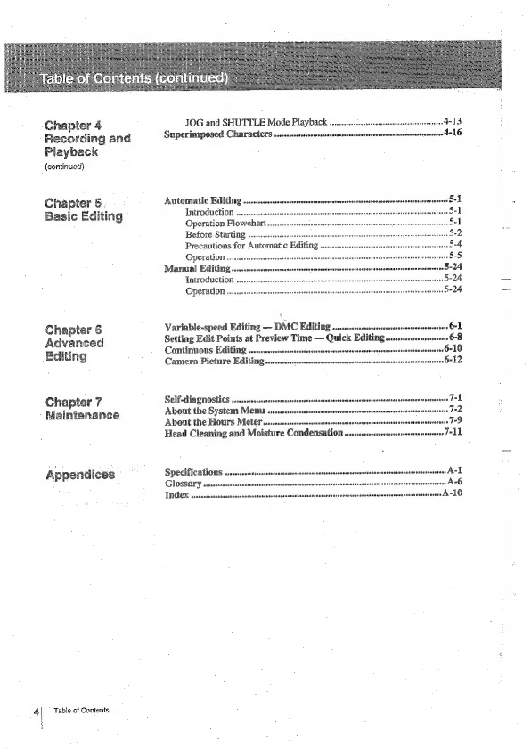
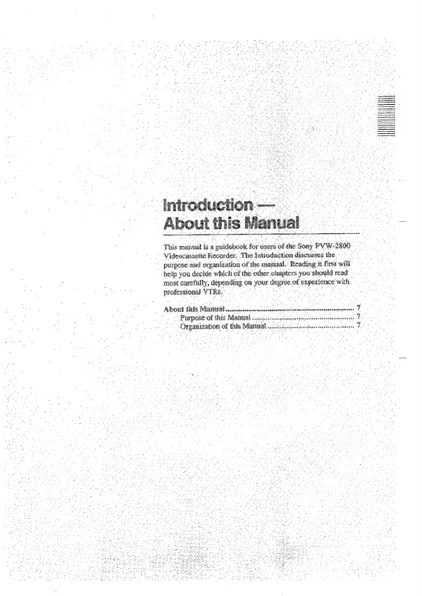
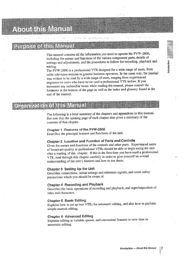
Sony PVW-2800 User manual

ve
Pee
nats
ae
tarsi
*
it
2000
PRO

Owner’s
Record
The
mode!
and
seria}
numbers
are
located
at
the
rear.
Record
the
serial
number
in
the
space
provided
below.
Refer
to
these
nurnbers
whenever
you
call
upon
your
Sony
dealer
regarding
this
product.
Model
No.
PVW-2800
Serial
No.
To
prevent
fire
or
shock
hazard,
do
not
expose
the
unit
to
rain
or
moisture.
RISK
OF
ELECTRIC
SHOCK
DO
NOT
OPEN
CAUTION:
TO
REDUCE
THE
RISK
OF
ELECTRIC
SHOCK,
DO
NOT
REMOVE
COVER
(OR
BACK).
NO
USER-SERVICEABLE
PARTS
INSIDE.
REFER
SERVICING
TO
QUALIFIED
SERVICE
PERSONNEL.
This
symbolis
intended
to
alert
the
userto
the
presence
of
uninsulated
“dangerous
voltage”
within
the
product's
enclosure
that
may
be
of
sufficient
magnitude
to
constitute
a
risk
of
electric
shock
to
persons.
This
symbolis
intended
to
alert
the
userto
the
presence
of
important
operating
and
main-
tenance
(servicing)
instructions
in
the
fitera-
ture
accompanying
the
appliance.
Thi
For
the
customers
in
the
USA
‘équipment
has
been
tested
and
found
to
comply
with
the
limits
for
a
Class
A
digital
device,
pursuant
to
Part
15
of
the
FCC
Rules.
These
limits
are
designed
to
provide
reasonable
protection
against
harmiul
interference
when
the
equipment
is
operated
in
a
commercial
environment.
This
equipment
generates,
uses,
and
can
radiate
radio
frequency
energy
and,
if
not
installed
and
used
in
accordance
with
the
instruction
rnanual,
may
cause
harmful
interference
to
radio
communications.
Operation
of
this
equipment
in
a
residential
area
is
likely
to
cause
harmful
interference
in
which
case
the
user
will
be
required
te
correct
the
interference
at
his
own
expense.
You
are
cautioned
that
any
changes
or
modifications
not
expressly
approved
in
this
manual
could
void
your
authority
to
operate
this
equiprnent.
The
shielded
interface
cable
recommended
in
this
manual
must
be
used
with
this
equipment
in
order
to
comply
with
the
limits
for
a
digital
device
pursuant
to
Subpart
B
of
Part
15
of
FCC
Rules.
For
customers
in
Canada
This
apparatus
complies
with
the
Class
A
limits
for
radio
noise
emissions
set
out
in
Radio
Interference
Regulations.
For
customers
in
the
USA
Television
programs,
films,
video
tapes
and
other
materiais
may
be
copyrighted.
Unauthorized
recording
of
such
material
may
be
contrary
to
the
provisions
of
copyright
laws.

introduction
=~
Aboutthis®
Manual
Chapter-1
.
Features
of
the
-
PYW-2600
Chapter
2
Location
and-
Function.
of
Parts
and
Controls
-
Chapter
3°
Setting
Up
the
Unit
:
Chapter
a
Recording.
and
Playback
(contin)
About
this
Mantaal
.....cessscssssssessssessneseree
Purpose
of
this
Manual
..
Organization
of
this
Manu:
The
Betacam
SP
Format...
Advanced
Editing
Functions
Ease
of
Operation
.......
Other
Features.
Control
Panel
(Front)
......
Upper
Control
Panel...
Lower
Control
Pane]
(Edit
ide
Comet:
System
Panel..
Precautions
....sscccssocrerseren
Safety
Precautions
..
Handling
Precautions
Connections
vesaasevacsosesanaseanerne
-3
Connections
of
Video
and
Audio
Equipment
.
-3
Connector
Pane]
Switch
Settings
..
Editing
System
Connections
....
Reference
Control
Settings
Main
Menu
.....
Changing
Menu
Settings
Reference
Signals
for
Time
Base
Corrector
and
Servo
System
About
Reference
Signals
Genlock
of
the
Built-in
Black
Burst
Generator
Selection
of
the
Reference
Signal
for
the
Servo
System
Reference
Signal
Connections
..
About
Cassettes
.....
Recommended
Cassettes
Inserting
and
Ejecting
the
Cassette
Preventing
Accidental
Erasure
ReCOFEIIG
«...sesseresecrsrersrsrneesrerarerernsersvessonsrsroanen!
Preparing
to
Record...
Recording
Video
and
Audio
Signals
Recording
Time
Codes
and
User
Bi
Playback:
....csesccssserreee
Preparing
for
Playback
.......
Normai
Speed
Playback
.....
Table
of
Contents

4
\
Chapter
4
Recording
and
Playback
(continued)
Chapter
5
Basic
Editing
Chapter
6
Advanced
Editing
Chapter
7
Maintenance
Appendices
Table
of
Conients
JOG
and
SHUTTLE
Mode
Playback
..
Superimposed
Characters
...ssccvesssresnnsersrerne
Automatic
Editing
Introduction
....
Operation
Flowchart.
Before
Starting
......
Precautions
for
Automatic
Editin;
Operation
...
Manual
Editing.
Introduction
Operation...
Variable-speed
Editing
—
DMC
Editing
.........
Setting
Edit
Points
at
Preview
Time
—
Quick
Editing
Continuous
Editing
......00-+0
Camera
Picture
Editing.......
Self-diagnostics
....srseccsene
About
the
System
Mens
....
About
the
Hours
Meter...
Head
Cleaning
and
Moisture
Condensation
Specifications
....-rsesees
Glossary
Index...

About
this
Manual
This
mada
isa
guidebook
for
tiser’
8
ihe
Sony
Py
w-2800
Videocassette
Recorder:
The
Introduction
discusses
the
~
purpose
and
organization
of
the
maatual.:
‘Reading.
ii
First
will
help
you
decide
which
of
the
other
chapters
you
should
read
most
carefully,
depending
on
your.
degree:
of
pices
with
professional
VTRes.
About
this
Manual
niece:
Purpose
of
this
Manual
.
Organization
of
this
Mat


This
manual
contains
all
the
information
you
need
to
operate
the
PVW-2800,
including
the
names
and
functions
of
the
various
component
parts,
details
of
settings
and
adjustments,
and
the
procedures
to
follow
for
recording,
playback
and
editing.
The
PVW-2800
is
a
professional
VIR
designed
for
a
wide
range
of
users,
from
cable
television
stations
to
general
business
operators.
In
the
same
way,
the
manual
was
written
to
be
read
by
a
wide
range of
users,
ranging
from
experienced
engineers
to
users
who
have
never
used
a
professional
VTR
before.
If
you
encounter
any
unfamiliar
terms
while
reading
the
manual,
please
consult
the
footnotes
at
the
bottom
of
the
page
as
well
as
the
index
and
glossary
found
at
the
end
of
the
manual.
The
following
is
a
brief
summary
of
the
chapters
and
appendices
in
this
manual.
But
note
that
the
opening
page
of
each
chapter
also
gives
a
summary
of
the
contents
of
that
chapter.
Chapter
1
Feaiures
of
the
PYW-2800
Describes
the
principal
features
and
functions
of
the
unit.
Chapter
2
Location
and
Function
of
Paris
and
Controls
Gives
the
names
and
functions
of
the
controls
and
other
parts.
Experienced
users
of
broadcast-quality
or
professional
VTRs
should
be
able
to
begin
using
the
unit
after
a
reading
of
this
chapter.
If
this
is
the
first
time
you
have
used
a
professional
VTR,
read
through
this
chapter
carefully
in
order
to
give
yourself
an
overall
understanding
of
the
unit’s
features
and
how
to
use
them.
Chapier
3
Setting
Up
the
Unit
Describes
connections,
initial
settings
and
reference
signals,
and
some
safety
precautions
which
you
should
be
aware
of.
Chapter
4
Recording
and
Playback
Describes
the
basic
operations
of
recording
and
playback,
and
superimposition
of
titles
and
characters.
Chapter
5
Basic
Editing
.
Explains
how
to
set
up
two
VTRs
for
automatic
editing,
and
also
how
to
perform
simple
manual
editing.
Chapter
6
Advanced
Editing
Explains
editing
at
variable
speeds,
and
convenient
features
to
save
time
in
automatic
editing.
Introduction
—
About
this
Manual
7
Introduction

€
Z
3
g
3
g
&
Chapter
7
Maintenance
Describes
the
unit’s
self-diagnosis
functions,
cleaning
and
maintenance,
and
the
setup
menu
for
less-used
features.
Appendices
©
Specifications
©
Glossary
@
Index
Technical
Terms
Technical
terms
are
explained
in
the
body
of
the
text
at
the
point
where
they
first
occur,
or
at
the
foot
of
the
page.
You
may
also
consult
the
glossary
of
terms
at
the
end
of
this
manual.
lilustrations
for
operating
procedures
As
a
general
rule,
the
numbers
indicated
in
the
illustrations
for
operating
procedures
correspond
to
the
operation
step
numbers
in
the
text
below
the
illustrations.
If
necessary,
the
names
of
the
parts
and
controls
to
be
used
for
the
operation
are
also
indicated
in
the
illustration.
Cross
References
Throughout
the
manual
you
will
find
italicized
references
to
sections
of
this
manual
or
other
manuals
which
contain
additional
information.
Also
printed
in
italics
are
questions
which
you
should
discuss
with
the
Sony
dealer
from
whom
you
purchased
this
unit.
important
Notes
Be
sure
to
read
the
sections
of
the
manual
marked
.
They
explain
points
which
you
should
be
aware
of
in
order
to
operate
the
unit
correctly
and
prevent
malfunctions.
8B!
Introduction
—-
About
this
Manual
|

Chapter
1
Features
of
the
PYW-2800_
This
chapter
describes
special
features
of
the.
unit
which
you.
should
be.aware
of
before
you
operate
it
it
The
Betacam
SP
Format
.
Advanced
Editing
Function:
Ease
of
Operation.
Other
Features
..


The
PVW-2800
is
a
professional
VIR
designed
for
use
by
cable
television
stations,
business
operators
and
others
who
require
the
high
quality
of
Sony’s
Betacam
SP
(Superior
Performance)
format.
Together
with
the
other
units
in
the
Betacam
SP
2000
PRO
series,
it
combines
high
cost
performance
with
the
advantages
of
the
SP
format,
widely
used
by
broadcasters
and
production
companies
throughout
the
world.
You
can use
the
PVW-2800
for
standalone
recording
and
playback,
or
connect
it
to
asecond
Betacam
SP,
U-matic,
Hi8
or
J-inch
VTR*
for
electronic
editing.
Metal
tape
Using
metal
particle
tape
and
newly
developed
video
heads,
the
SP
format
offers
improved
signal-to-noise
ratios,
better
frequency
response,
and
superior
waveform
and
detai}
reproduction
characteristics.
The
high
durability
of
metal
tape
makes
the
unit
suitable
for
use
in
demanding
professional
applications.
Metal
tape
offers
excellent
frequency
response
and
low-
distortion
longitudinal
(LNG**)
recording,
and
video
quality
remains
high
even
after
multiple
dubbings.
Longer
recording
and
playing
time
Compared
to
the
30
minutes
of
conventional
small
cassette
tapes,
the
large
cassette
tapes
used
in
the
Betacam
SP
format
offer
a
maximum
of
90
minutes
of
recording
and
playing
time.
*
Connectable
equipment;
Betacam
SP
VTRs:
BYW-35/S0/70/75
Betacam
SP
videocassette
players:
PV
W-2600/2650,
BVW-60/65
Betacam
VIRs:
BY
W-40
Betacam
videocassette
players:
BVW-10/15
U-matic
VTRs:
BVU-800/820/950
1-inch
helical
scan
VFRs:
BVH-2006/2500/3000/3
100
Hi8
VTRs:
EVO-9500A/9800A
**
LNG
(Longitudinal):
Longitudinal
recording
is
the
method
used
by
conventional
tape
recorders.
Tracks
along
the
length
of
the
tape
are
recorded
with
high-frequency
bias
by
moving
the
tape past
fixed
recording
heads.
Chapter
i
Features
of
the
PYW-2800
1-1
i

i
Compatibility
with
conventional
Betacam
SP
VTRs
Regardless
of
tape
type,
metal
or
oxide,
a
cassette
tape
recorded
with
this
unit
can
be
played
back
on
a
conventional
Betacam
SP
VTR.
The
unit
automatically
detects
the
size
of
the
cassette,
and
determines
whether
the
tape
is
metal
or
oxide.
Metal
or
oxide
cassettes
recorded
with
a
conventional
Betacarn
SP
VTR
may
also
be
played
back
on
this
unit.
However,
AFM*
(Audio
Frequency
Modulation)
recording
and
playback
is
not
possible.
You
can
connect
two
PVW-2800s
to
perform
manual
or
automatic
editing
in
assemble
or
insert
mode.
The
unit
features
a
wide
variety
of
editing
functions,
including
preview,
review,
preroll,
and
entry
or
trimming
of
edit
points,
Quick
access
to
edit
points
The
search
dial
gives
you
quick
access
to
edit
points
via the
SHUTTLE
mode,
with
19
speeds
ranging
from
0
to
+24
times
normal
speed,
and
the
JOG
mode,
which
gives
you
a
choice
of
any
speed
between
0
and
+1.
Color
pictures
may
be
monitored
at
speeds
from
0
to
+10
times
normal
speed.
In
INSERT
mode,
you
can
set
audio
and
video
edit
points
separately,
Edit
duration
display
By
simultaneously
pressing
any
two
of
the
IN,
OUT,
AUDIO
IN
and
AUDIO
OUT
buttons,
you
can
display
the
duration
between
any
two
points.
Digital
time
counter
The
unit’s
time
counter
display
indicates
the
CTL**
running
time,
LTC/VITC***
time
code,
or
user
bit
data,
for
precise
setting
of
edit
points.
*
AFM
(Audio
Frequency
Modulation):
Audio
signals
are
subjected
to
frequency
modulation,
and
recorded
together
with
the
FM
video
signals
in
the
video
tracks.
st
CTL
(Control
Signal):
Pulse
signals
used
to
control
tape
movement
and
head
position
during
recording
and
playback.
1-2
Chapter
1
Features
of
the
PYW-2800
**%
LTC
(Longitudinal
Time
Cede):
A
frame-rate
time
code
recorded
on
the
longitudinal
time
code
track.
VITC
(Vertical
Interval
Time
Code):
A
field-rate
time
code
recorded
in
video
tracks
during
the
vertical
(blanking)
interval.

Set
up
and
control
menus
Settings
for
control
of
the
unit
or
the
interface
to
other
components
are
easily
adjusted
via
menus,
using
controls
Jocated
on
the
front
panel.
Built-In
time
code
generator
and
reader
The
built-in
time
code
generator
allows
you
to
record
LTC/VITC
time
codes
or
user
bits
together
with
video
or
audio
signals.
Time
codes
and
user
bits
are
read
back
by
the
built-in
time
code
reader
during
playback.
Chapter
1
|
Computer
servo
system
Four
computer-controlled
servo
motors
in
the
unit
drive
the
drum,
capstan
and
two
reels,
for
quick
and
accurate
tape
access.
Limiter
circuits
and
independent
volume
control
You
can
set
maximum
recording
levels
to
trigger
limiter
circuits,
preventing
distortion
by
excessive
audio
input.
‘The
recording
and
playback
levels
of
the
two
audio
channels
can
be
set
independently.
Dolby
noise
reduction
system
The
built-in
Dolby
C*
noise
reduction
system
uses
the
same
circuitry
adopted
for
other
components
in
the
Betacam
SP
series.
Dolby
noise
reduction
can
be
turned
on
or
off
as
necessary
for
oxide
tape
playback.
Built-in
time
base
corrector
The
unit
features
a
built-in
time
base
corrector
to
adjust
for
timing
irregularities.
The
unit’s
output
signals
comply
with
standards
for
video
output
signals,
and
may
be
used
to
supply
stable
video
signals
directly
to
all
kinds
of
video
equipment.
Easy-to-use
front
panel
All
important
controls
have
been
concentrated
on
the
easy-to-use
front
panel,
which
is
divided
into
an
upper
and
a
Jower
control
panel,
The
lower
contro!
panel
can
be
tilted
for
the
operator's
convenience.
Mounts
in
standard
19-inch
rack
The
PVW-2800
can
be
mounted
in
an
EIA
standard
19-inch
rack.
Please
contact
your
Sony
dealer
for
details
regarding
rack
mounting.
¥
Dolby
noise
reduction
manufactured
under
licence
from
Dolby
Laboratories
Licensing
Corporation.
Corporation.
“DOLBY”
and
the
double-D
symbol
OU
are
Chapter
1
Features
of
the
PVW-2800
1-3

Compact,
lightweight,
low
power
consumption
The
unit
can
be
taken
out
of
the
studio
for
use
in
a
variety
of
Electronic
Field
Production
(EFP)
assignments.
Chapter
1
4
Remote
control
operation
The
PVW-2800
can
be
controlled
from
an
external
unit
over
the
standard
RS-422A
serial
interface.
A
BKW-2010
control
panel
extension
kit
is
required
to
use
the
control
panel
from
a
remote
location.
Please
contact
your
Sony
dealer
for
more
information
on
the
BEW-2010
control
panel
extension
kit.
ai
hours
meter
Four
different
kinds
of
hour
values
can
be
displayed:
total
elapsed
time
since
the
unit
was
turned
on,
total
drum
revolutions,
total
tape
running
time
and
total
threadings
and
unthreadings.
Superimposed
output
Time
codes,
tape
speed
and
other
information
can
be
superimposed
on
video
signal
output
and
the
monitor
display.
Superimposition
can
be
turned
on
and
off
as
necessary.
Seli-diagnostics
In
the
event
of
a
malfunction,
the
unit
performs
self-diagnostics
and
displays
an
error
code
in
the
time
counter
display
on
the
front
panel.
§-VIDEO
connector
The
PVW-2800
can
be
connected
to
any
VTR
or
other
component
having
an
S-
VIDEO
connector,
to
exchange
video
signals
with
very
little
degradation.
U-matie
dubbing
connector
The
unit
is
equipped
with
a
U-matic
video
output
dubbing
connector.
You
can
use
the
connector
to
perform
editing
and
dubbing
to
another
unit
with very
little
degradation.
The
optional
BKW-2020
U-matic
dubbing
output
kit
is
required
to
use
this
connector.
Please
contact
your
Sony
dealer
for
more
information
on
the
BKW-2020
U-matic
dubbing
output
kit.
Chapter
1
Features
of
the
PVW-2800.

Chapter
2
Location
and
Function
of:
Parts
and
Controls
_
This
chapter
gives.
brief
deséription
of
the
purposes
aid
functions
of
the
principal
parts
of
the
unit.
Tf
you
have
used.a
professional
VTR
before,
you"
should
be
able
to
begin
using
the
unit
aftera
reading
of
this
chapter.
ff
this
is
the
first
time
you
have
used'a
professional
VTR,
read
through
this
chapter
to
familiarize
-yourself
with
the
controls,
then
follow
the
procedures
for
setup
anid
operation
given
in
Chapter
3
and
following,
Refer
to
this
chapter
and
the
anges
to
clarify
the
functions
of
the
various
controls.
Control
Panel
(Front)
Upper
Control
Panel...
Lower
Control
Panel
Editing
Conse)
System
Panel
.-.rsrcsosviversrssessnesnessets
Connector
Pamel
(Rear)
.sssssseese
i


=
|
|
1]
POWER
switen
———-——~——[2]
HEADPHONES
jack
and
volume
level
controt
—~{3]
Audio
tevel
meters
—{4]
REC
tevel
controls
———~{5]
aupio
MONITOR
switch
ie
Cassette
compartment
[8]
aupio
LIMITER
switch
Ey
Indicators
-———-—-—
fi]
VIDEO/RF
mater.
[0]
nseut
SELECT
ewiteh
————--—---—~
id
[J
viveo
tevel
contro!
os
_
a
ees
[13]
TRACKING
contro}
--—~-
>
—
[14]
REMOTE/LOCAL
switeh-——
POWER
switch
Set
the
switch
to
ON
ta
turn
on
the
power.
The
audio
Ievel
meter,
VIDEO/RF
meter
and
time
counter
display
will
light
up.
[2]
HEADPHONES
jack
and
volume
level
control
Connect
8Q
stereo
headphones
to
monitor
the
signal
selected
with
the
AUDIO
MONITOR
switch.
Adjust
the
volume
with
the
volume
level
control.
Chapter
2
Location
and
Function
of
Parts
and
Contrals
j

;
E
ea)
(4)
EA
*
EE
mode
(Electric
to
Electric
mod
Audio
level
meters
Indicate
recording
level
in
REC
or
EE*
modes,
and
playback
level
in
PLAY
mode.
REC
(recording)
level
controls
You
can
adjust
audio
recording
levels
independently
for
each
channel.
To
adjust
the
recording
level,
put
the
unit
into
EE
mode,
pull
out
the
control
and
adjust
while
monitoring
the
audio
level
meters.
Hf
the
controls
are
pushed
in,
the
recording
level
is
fixed
at
the
factory
preset
level
and
cannot
be
adjusted.
(The
reading
of
the
Jeve]
meters
for
the
preset
level
is
O
VU
when
the
signal
is
input
at
+4
dBu**.)
Contact
your
Sony
dealer
if
you
wish
to
change
the
preset
audio
recording
level.
PB
(playback)
level
controls
You
can
adjust
audio
playback
levels
independently
for
each
channel.
To
adjust
the
playback
level,
put
the
unit
in
PLAY
mode,
pull
out
the
control
and
adjust
while
monitoring
the
audio
level
meter.
If
the
controls
are
pushed
in,
the
audio
playback
level
is
fixed
at
the
factory
preset
level
and
cannot
be
adjusted.
Contact
your
Sony
dealer
if
you
wish
to
change
the
preset
audio
playback
level.
AUDIO
MONITOR
switch
Select
the
audio
output
to
the
HEADPHONES
jack,
8-pin
MONITOR
connector
and
the
AUDIO
MONITOR
connector
(XLR
type)
on
the
rear
panel
by
setting
the
switch
to
one
of
the
following
settings.
7|
Cassette
compartment
oe
¢
CH-1
|
Channel
i
audio
|
Channel
4
audio
MIX
|
Stereo
audio
Mixed
Channel
1
and
2
audio
CH-2
|
Channel
2
audio
|
Channei
2
audio
Audio
and
video
signals
input
inte
the
VIR’s
recording
circuits
are
supplied
to
other
circuits,
but
not
to
the
recording
heads.
2-2)
Chapter
2
Location
and
Function
of
Parts
and
Controls
Insert
cassettes
here,
To
insert
a
small
cassette,
align
it
with
the
marks
in
center
of
the
compartment
window.
[8]
AUDIO
LIMITER
switch
0]
After
adjusting
the
recording
levels,
set
this
switch
to
ON
io
activate
the
limiter
circuits.
These
circuits
prevent
distortion
due
to
excessive
input,
for
example
a
sudden
Joud
noise
during
microphone
recording.
[2]
indicators
AUTO
OFF
indicator
Lights
when
moisture
condensation
is
detected
on
the
head
drum
and
when
tape
transport
irregularities
are
detected.
DOLBY
NR
indicator
Lights
when
the
DOLBY
noise
reduction
circuits
are
activated.
LTC
indicator
PLAY
mode:
Lights
if
recorded
LTC
signals
are
detected
on
the
tape.
REC,
EE
modes:
Always
lights,
unless
the
input
is
from
an
external
source
which
does
not
generate
LTC
signals
although
the
TC
GENERATOR
EXT/
INT
switch
on
the
system
panel
is
set
to
EXT
and
the
REGEN/PRESET
switch
to
PRESET.
VITC
indicator
PLAY
mode:
Lights
if
recorded
VITC
signals
are
detected
on
the
tape.
REC,
EE
modes:
Lights
if
VITC
signals
are
being
inserted
into
the
video
signals.
**
0
dBu
=
0.775
Vrins

FS]
ik]
INPUT
SELECT
switch
Selects
input
video
signals
for
recording
or
editing.
COMPOSITE:
Record
or
edit
composite
signals
from
the
VIDEO
INPUT
connectors.
Y-R,B:
Record
or
edit
¥
(Luminance),
R-Y,
and
B-Y
(Chrominance)
signals
from
the
COMPONENT
1
connector‘or
the
three
COMPONENT
2
connectors,
selected
with
the
COMPONENT
connector
select
switch
on
the
connector
panel.
§-VIDEQ:
Record
or
edit
Y
(Luminance)
and
C
(Chroma:
3.58MHz)
signals
from
the
S-VIDEO
input
connector.
11]
VIDEO/AF
meter
In
REC
or
EE
mode,
indicates
the
video
signal
recording
level.
In
PLAY
mode,
indicates
the
tape
tracking
status
(RF
signal
level).
VIDEO
level
control
Allows
you
to
adjust
the
video
recording
level,
but
only
if
the
unit
is
in
EE
mode
and
the
INPUT
SELECT
switch
is
set
to
COMPOSITE.
To
adjust
the
video
recording
level,
pull
out
this
control
and
adjust
it
so
that
the
pointer
of
the
YVIDEO/RF
meter
is
in
the
blue
zone.
When
this
control
is
pushed
in,
the
video
secording
level
is
set
automatically
to
an
appropriate
level.
TRACKING
control
During
playback,
adjusts
the
tape
tracking.
If
noise
appears
in
the
picture,
adjust
this
control
so
that
the
pointer
of
the
VIDEO/RF
meter
indicates
the
maximum
RF
level.
Normally
this
control
should
be
set
to
the
center
FIXED
position.
During
recording,
this
control
must
be
set
to
the
center
FLXED
position.
REMOTE/LOCAL
switch
Set
this
switch
to
control
the
unit
locaily
or
from
equipment
connected
to
the
REMOTE
connector
on
the
rear
panel.
REMOTE:
The
unit
is
controlled
from
an
extemal
component
connected
to
the
9-pin
REMOTE
connector
on
the
rear
panel,
Setting
this
switch
to
REMOTE
disables
all
tape
transport
buttons
on
the
control
panel,
except
for the
STOP
and
EJECT
buttons.
Ifyou
wish,
you
can
enable
any
buttons
including
the
STOP
and
EJECT
buttons,
or
disable
all
buttons.
For
more
information,
refer
to
the
explanation
of
Main
Menu
item
006
on
page
3-8.
LOCAL;
The
unit
is
controlled
from
its
control
panel.
Chapier
2
Location
and
Function
of
Paris
and
Controls
2-3

INSERT
buttons:
~-~[4]
pme
epit
button
‘—[8]
aupio
mnvourt
butions
and
MEMORY
\—{10]
enTAY
button
5]
PREVIEW
butt
L
’
iB)
i
ff]
invour
buttons
'
indicator
Gy
AUTO
EDIT
button
i)
REVIEW
bution
How
to
tilt
the
lower
control
panel
[=|
DELETE
button
‘|
Raise
the
panel
to
the
desired
angle.
2
While
pressing
the
levers
al
the
right
and
left
sides
of
the
panel,
pull
the
panel
up
unilt
it
stops.
:
3
Tighten
the
screws
on
the
right
and
left
sides
inside
the
panel
i
by
turring
them
clockwise.
4
While
pressing
ihe
ievers,
lower
the
panel
to
the
desired
angle.
2-4
Chapter
2
Location
and
Function
of
Parts
and
Gontrois
Other manuals for PVW-2800
3
Table of contents
Other Sony Measuring Instrument manuals

Sony
Sony LE-SP6800 Series Installation and operating manual

Sony
Sony MG40 Series Installation manual

Sony
Sony TC-377 User manual

Sony
Sony DK805AR User manual

Sony
Sony Ipela NSR-S20 User manual

Sony
Sony TC-788-4 Setup guide

Sony
Sony PWS-100TD1 User manual

Sony
Sony TC-260 User manual

Sony
Sony MZ-N920 User manual

Sony
Sony HDR-CX620 User manual

Sony
Sony AXS-R7 User manual

Sony
Sony PCM-D100 User manual

Sony
Sony DCR-PC115 User manual

Sony
Sony Handycam DCR-TRV6 User manual

Sony
Sony DG155BPM User manual

Sony
Sony ICD-LX30 User manual

Sony
Sony PCM-A10 User manual

Sony
Sony M-640V - Microcassette Recorder User manual

Sony
Sony AM-NX9 User manual

Sony
Sony TC-730 User manual