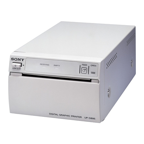
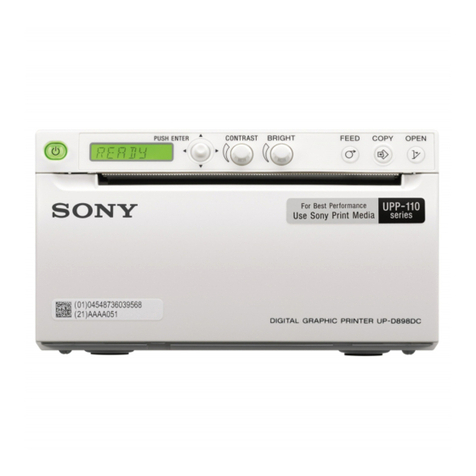
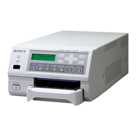
Sony UP-D711MD User manual

Digital Graphic Printer
Instructions for Use
Before operating the unit, please read this manual thoroughly
and retain it for future reference.
UP-D711MD
4-417-500-16 (1)
2017-08
© 2012 Sony Corporation

2
Indications for Use/Intended Use
The Sony UP-D711MD printer is a compact, medical
grade black and white digital printer. It is designed to be
integrated into digital radiology imaging systems such
as mobile c-arm, ultrasound, cardiac cath lab and other
compatible medical imaging systems and produce hard
copy prints of still images captured by these systems for
the patient record or for referrals.
Notes
• Output images from this equipment cannot be used for
diagnostic use.
• This equipment is for medical professionals.
• This equipment is intended for use in medical
environments, such as clinics, examination rooms,
and operating rooms.
To reduce the risk of fire or electric shock, do
not expose this equipment to rain or moisture.
To avoid electrical shock, do not open the
cabinet. Refer servicing to qualified personnel
only.
No modification of this equipment is allowed.
WARNING
Symbols on the product
Safety sign
Follow the warnings in the instructions for
use for parts of the unit on which this symbol
appears.
NOTE Background color: Blue
Symbol: White
Consult the instructions for use
Follow the directions in the instructions for
use for parts of the unit on which this symbol
appears.
This symbol indicates the manufacturer, and
appears next to the manufacturer’s name and
address.
This symbol indicates the date of
manufacture.
This symbol indicates the serial number.
This symbol indicates the version of the
accompanying document.
Storage and transport temperature
This symbol indicates the acceptable
temperature range for storage and transport
environments.
Storage and transport humidity
This symbol indicates the acceptable
humidity range for storage and transport
environments.
Storage and transport pressure
This symbol indicates the acceptable
atmospheric pressure range for storage and
transport environments.
This symbol indicates the European
Community representative, and appears next
to the European Community representative’s
name and address.
For accessories
This symbol indicates the batch code.
This symbol indicates that re-use is not
permitted.

3
For customers in the U.S.A.
This equipment has been tested and found to comply
with the limits for a Class A digital device, pursuant to
part 15 of the FCC Rules. These limits are designed to
provide reasonable protection against harmful
interference when the equipment is operated in a
commercial environment. This equipment generates,
uses and can radiate radio frequency energy and, if not
installed and used in accordance with the instruction
manual, may cause harmful interference to radio
communications. Operation of this equipment in a
residential area is likely to cause harmful interference in
which case the user will be required to correct the
interference at his own expense.
You are cautioned that any changes or modifications not
expressly approved in this manual could void your
authority to operate this equipment.
All interface cables used to connect peripherals must be
shielded in order to comply with the limits for a digital
device pursuant to Subpart B of part 15 of FCC Rules.
For customers in the U.S.A.
Caution
Federal law (United States of America) restricts this
device to sale by or on the order of a licensed healthcare
practitioner.
For customers in Canada
This unit has been certified according to Standard CAN/
CSA-C22.2 No.60601-1.
Important safeguards and notices for use
in the medical environments
1. All devices connected to the unit must be certified or
compliant according to IEC 60601-1, IEC 60950-1,
and IEC 60065 standards and other IEC/ISO
standards applicable to the devices.
2. Furthermore, the system as a whole must comply
with IEC 60601-1 standards. All peripheral devices
connected to the signal input/output sections of the
unit constitute the medical-use system, and
therefore, the user is responsible for ensuring that the
system as a whole complies with IEC 60601-1
standards. If in doubt, consult qualified Sony service
personnel.
3. Connecting the unit to other devices may increase the
leakage current.
4. For all peripheral devices connected to the unit that
operate on commercial power supplies and do not
comply with IEC 60601-1 standards, incorporate an
isolation transformer that complies with IEC 60601-
1 standards and connect to the commercial power
supply via the transformer.
5. The unit generates, uses, and may radiate radio
frequency energy. If it is not installed and used in
accordance with the instruction manual, it may cause
interference on other devices. If the unit causes
interference (which can be determined by
disconnecting the power cord from the unit), try the
following.
– Relocate the unit with respect to the affected
devices.
– Connect the unit and the affected devices to
different branch circuits.
For more information, consult qualified Sony service
personnel.
(Applicable standard: IEC 60601-1-2)

4
Important EMC notices for use in medical environments
• The UP-D711MD needs special precautions regarding EMC and needs to be installed and put into service according
to the EMC information provided in the instructions for use.
• Portable and mobile RF communications equipment, such as cellular phones, can affect the UP-D711MD.
WARNING
The use of accessories and cables other than those specified, with the exception of replacement parts sold by Sony
Corporation, may result in increased emissions or decreased immunity of the UP-D711MD.
WARNING
If the UP-D711MD will be used adjacent to or stacked with other equipment, normal operation of the UP-D711MD
under such configurations should be verified via observation.
Guidance and manufacturer’s declaration – electromagnetic emissions
The UP-D711MD is intended for use in the electromagnetic environment specified below.
The customer or the user of the UP-D711MD should assure that it is used in such an environment.
Emission test Compliance Electromagnetic environment – guidance
RF emissions
CISPR 11 Group 1
The UP-D711MD uses RF energy only for its internal
function. Therefore, its RF emissions are very low
and are not likely to cause any interference in nearby
electronic equipment.
RF emissions
CISPR 11
Class B
The UP-D711MD is suitable for use in all
establishments, including domestic establishments
and those directly connected to the public low-voltage
power supply network that supplies buildings used for
domestic purposes.
Harmonic
emissions
IEC 61000-3-2
Not applicable
Voltage
fluctuations/flicker
emissions
IEC 61000-3-3
Not applicable

5
Guidance and manufacturer’s declaration – electromagnetic immunity
The UP-D711MD is intended for use in the electromagnetic environment specified below. The customer or
the user of the UP-D711MD should assure that it is used in such an environment.
Immunity test IEC 60601
test level
Compliance
level Electromagnetic environment – guidance
Electrostatic
discharge (ESD)
IEC 61000-4-2
±6 kV contact
±8 kV air
±6 kV contact
±8 kV air
Floors should be wood, concrete or ceramic tile. If
floors are covered with synthetic material, the
relative humidity should be at least 30%.
Electrical fast
transient/burst
IEC 61000-4-4
±2 kV for power
supply lines
±1 kV for input/
output lines
±1 kV for input/
output lines
Mains power quality should be that of a typical
commercial or hospital environment.
Surge
IEC 61000-4-5
±1 kV line(s) to
line(s)
±2 kV line(s) to
earth
Not applicable Mains power quality should be that of a typical
commercial or hospital environment.
Voltage dips,
short
interruptions and
voltage
variations on
power supply
input lines
IEC 61000-4-11
< 5% UT
(> 95% dip in
UT)
for 0.5 cycle
40% UT
(60% dip in UT)
for 5 cycles
70% UT
(30% dip in UT)
for 25 cycles
< 5% UT
(> 95% dip in
UT)
for 5 sec
Not applicable Mains power quality should be that of a typical
commercial or hospital environment. If the user of
the UP-D711MD requires continued operation
during power mains interruptions, it is
recommended that the UP-D711MD be powered
from an uninterruptible power supply or a battery.
Power frequency
(50/60 Hz)
magnetic field
IEC 61000-4-8
3 A/m 3 A/m Power frequency magnetic fields should be at
levels characteristic of a typical location in a typical
commercial or hospital environment.
NOTE: UTis the a.c. mains voltage prior to application of the test level.

6
Guidance and manufacturer’s declaration – electromagnetic immunity
The UP-D711MD is intended for use in the electromagnetic environment specified below. The customer or
the user of the UP-D711MD should assure that it is used in such an environment.
Immunity test IEC 60601
test level
Compliance
level Electromagnetic environment – guidance
Conducted RF
IEC 61000-4-6
Radiated RF
IEC 61000-4-3
3 Vrms
150 kHz to
80 MHz
3 V/m
80 MHz to
2.5 GHz
3 Vrms
3 V/m
Portable and mobile RF communications
equipment should be used no closer to any part of
the UP-D711MD, including cables, than the
recommended separation distance calculated from
the equation appliance to the frequency of the
transmitter.
Recommended separation distance
d= 1.2 √P
d= 1.2 √P80 MHz to 800 MHz
d= 2.3 √P800 MHz to 2.5 GHz
Where Pis the maximum output power rating of
the transmitter in watts (W) according to the
transmitter manufacturer and dis the
recommended separation distance in meters (m).
Field strengths from fixed RF transmitters, as
determined by an electromagnetic site survey, a
should be less than the compliance level in each
frequency range. b
Interference may occur in the vicinity of equipment
marked with following symbol:
NOTE 1: At 80 MHz and 800 MHz, the higher frequency range applies.
NOTE 2: These guidelines may not apply in all situations. Electromagnetic propagation is affected by
absorption and reflection from structures, objects and people.
a Field strengths from fixed transmitters, such as base stations for radio (cellular/cordless) telephones
and land mobile radios, amateur radio, AM and FM radio broadcast and TV broadcast cannot be
predicted theoretically with accuracy. To assess the electromagnetic environment due to fixed RF
transmitters, an electromagnetic site survey should be considered. If the measured field strength in the
location in which the UP-D711MD is used exceeds the applicable RF compliance level above, the
UP-D711MD should be observed to verify normal operation. If abnormal performance is observed,
additional measures may be necessary, such as reorienting or relocating the UP-D711MD.
b Over the frequency range 150 kHz to 80 MHz, field strengths should be less than 3 V/m.

7
Caution
When you dispose of the unit or accessories, you must
obey the laws in the relative area or country and the
regulations in the relative hospital regarding
environmental pollution.
Caution
Do not use the device in a MR (Magnetic Resonance)
environment.
It may cause a malfunction, fire, and unwanted
movement.
Recommended separation distances between portable and mobile RF communications equipment
and the UP-D711MD
The UP-D711MD is intended for use in an electromagnetic environment in which radiated RF disturbances
are controlled. The customer or the user of the UP-D711MD can help prevent electromagnetic interference
by maintaining a minimum distance between portable and mobile RF communications equipment
(transmitters) and the UP-D711MD as recommended below, according to the maximum output power of
the communications equipment.
Rated maximum output power of
transmitter
W
Separation distance according to frequency of transmitter
m
150 kHz to 80 MHz
d= 1.2 √P
80 MHz to 800 MHz
d= 1.2 √P
800 MHz to 2.5 GHz
d= 2.3 √P
0.01 0.12 0.12 0.23
0.1 0.38 0.38 0.73
1 1.2 1.2 2.3
10 3.8 3.8 7.3
100 12 12 23
For transmitters rated a maximum output power not listed above, the recommended separation distance d
in meters (m) can be estimated using the equation applicable to the frequency of the transmitter, where P
is the maximum output power rating of the transmitter in watts (W) according to the transmitter
manufacturer.
NOTE 1: At 80 MHz and 800 MHz, the separation distance for the higher frequency range applies.
NOTE 2: These guidelines may not apply in all situations. Electromagnetic propagation is affected by
absorption and reflection from structures, objects and people.
For the customers in the U.S.A.
SONY LIMITED WARRANTY - Please visit
http://www.sony.com/psa/warranty for important
information and complete terms and conditions of
Sony’s limited warranty applicable to this product.
For the customers in Canada
SONY LIMITED WARRANTY - Please visit
http://www.sonybiz.ca/pro/lang/en/ca/article/
resources-warranty for important information and
complete terms and conditions of Sony’s limited
warranty applicable to this product.
For the customers in Europe
Sony Professional Solutions Europe - Standard
Warranty and Exceptions on Standard Warranty.
Please visit http://www.pro.sony.eu/ warranty for
important information and complete terms and
conditions.
For the customers in Korea
SONY LIMITED WARRANTY - Please visit
http://bpeng.sony.co.kr/handler/BPAS-Start for
important information and complete terms and
conditions of Sony’s limited warranty applicable to
this product.

8
Table of Contents
Getting Started
Overview .................................................................9
Location and Function of Parts and Controls .....9
Front Panel ..........................................................9
Rear Panel .........................................................10
Checking the accessories .....................................11
Connections ..........................................................11
Connecting to the USB Connector ...................12
Connecting the DC Cable .................................12
Installing the Printer Driver ..............................12
Paper .....................................................................13
Paper You Can Use ...........................................13
Loading Paper in the Unit ...................................13
Loading Paper ...................................................14
Operation
Printing .................................................................15
Starting a Print Job ...........................................15
Canceling a Print Job ........................................15
Feeding Paper ...................................................15
Cutting Paper ....................................................15
Others
Precautions ...........................................................16
Notes on use ......................................................16
On Safety ..........................................................16
On Installation ..................................................16
On the Printer Carriage .....................................16
Cleaning the Cabinet .........................................17
Cleaning the Thermal Head ..............................17
Cleaning the Platen Roller ................................18
Specifications ........................................................19
Troubleshooting ....................................................20
Lamp Indicators ................................................21
Index ......................................................................22

9
Getting Started
Overview
This unit is a printer that prints images by heating a
thermal head, according to the input image data, and
pressing the head against special thermal printing paper
to print the image on the paper. It features the following
characteristics.
Quiet, High Quality, Fast Printing
• Employs a thin thermal head with a built-in high speed
drive IC, capable of high resolution images of
11.8 dots/mm.
• Print speeds of approximately 1 high quality image
(896 × 1196 dots (approx. 76 × 101 mm)) every
5 seconds when the “High Speed Print Mode”
checkbox is on.
• Standard image memory capable of handling and
printing images up to 896 ×2688 dots (approx. 76 ×
227 mm).
• Monochrome printing with up to 256 shades of
gradation.
USB interface
The unit is equipped with a USB connector which
complies with the USB specification.
Easy Paper Loading
Free access to the door allows you to drop paper into the
unit for easy loading.
Location and Function
of Parts and Controls
For more details, see the referenced page numbers
enclosed in parentheses ( ).
Front Panel
A1On/standby switch
1On/standby lamp
(14, 15, 17)
Press to turn the unit on (1On/standby lamp
lights).
BPRINT lamp
Lights while printing.
CFEED button (14, 15)
Hold down to feed paper.
The paper will only feed when the button remains
pressed.
If insufficient paper has been fed after printing,
press the button for a short time to feed extra paper.
For details on feeding paper after printing, see
“Setup Guide.”
Press to cancel a print job that is currently in
progress.
DPAPER lamp
Lights when the paper is not set in the tray correctly
or if the tray is empty.
EALARM lamp
Lights when the door is open or if a problem occurs
in the printer.
FOPEN button (14)
Press to open the door.
Press and hold down this button all the way, to open
the door.
OPEN
ALARM
PAPER
FEED
PRINT

10
GPaper cutter
Cuts the paper as each image is printed.
About the lamp indicators
The lamp lights or blinks to show the state of the printer.
For details, see “Lamp Indicators” (page 21)
Rear Panel
AUSB connector (12)
Connects to a computer equipped with a USB
interface.
Do not use a USB cable longer than 3 meters.
BDC connector
Use a Hosiden–manufactured connector to connect.
Part no: TCP8927-53
Wire rod: For voltages above 60V at max. The wire
rod’s rating must be more than 7A.
Warning on power supply devices
For the DC power supply, be sure to use the AC adapter
that is supplied or one that is recommended, or a device
that complies with the IEC 60601-1 standard and is
protected by double insulation or reinforced insulation.
Be sure to use a power supply device capable of
supplying a voltage of 12 V to 24 V and a current of 6 A
(at 12 V) to 3 A (at 24 V) or more.
However, the device should not be capable of supplying
240 VA for 60 seconds or more (20 A or less at 12 V,
10 A or less at 24 V).
Use of power supply devices other than the above may
result in fire or electric shock.
Class I devices should only be connected to a power
outlet that is properly earthed to avoid the risk of electric
shock.
For information on how to shut off the main power
supply, refer to the instructions for use supplied with the
power supply device.
If the information is not available for whatever reason,
obey the following.
• To shut off the main power, disconnect the power plug
from the outlet.
• When installing the unit, incorporate a readily
accessible shutoff device in the fixed wiring, or
connect the power plug to a power outlet near the unit
that can be easily accessed during use.
• Do not install the ME unit in a position that will make
unplugging the power plug difficult.
• If a malfunction occurs, cut power via the shutoff
device, or disconnect the power plug from the outlet.
Caution
Connect the DC connector to the unit, then supply the
power source to the unit.
To remove the DC connector, disconnect the power
source first, then remove the DC connector.
Do not touch the DC connector pin and a patient at the
same time.
A voltage of 12 to 24 V is applied to the DC connector
pin and may have a harmful effect on the patient.
GND
DC12~24V
(6-3A)
NC

11
Checking the
accessories
Check the accessories.
Thermal head cleaning sheet (1)
Before Using this Printer (1)
CD-ROM (1)
Service Contact List (1)
European Representative (1)
Connections
With the DC cable disconnected from the external power
supply, connect the USB connecting cable between the
unit and computer, then connect the DC cable. For
details about the unit connection, refer to the manuals
for the computer or other peripheral devices.
WARNING
Using this unit for medical purposes
The connectors on this unit are not isolated.
Do not connect any device other than one which
conforms to IEC 60601-1 standards.
When an information technology device or AV device
that uses an alternating current is connected, current
leakage may result in an electric shock to the patient or
operator.
If use of such a device is unavoidable, isolate its power
supply by connecting an isolation transformer, or by
connecting an isolator between the connecting cables.
After implementing these measures, confirm that the
reduced risk now conforms to IEC 60601-1 standards.
Notes
• Make sure that the USB cable is connected securely at
both ends.
• Make sure that the DC cable is connected securely
until it is locked.
• The unit drive software provided with the unit is not
suitable for using the unit connected to a network.
• Printer operation is not guaranteed when connecting
to the computer using the USB cable via a USB hub.
• Use a DC 12 V – DC 24 V power supply with at least
72 W, for the unit.
(DC12V 6A or greater, DC24V 3A or greater)
• Before connecting or disconnecting the DC cable, be
sure to turn the external power supply off. Otherwise
damage to the unit may result.

12
Connecting to the USB Connector
Connecting the DC Cable
Installing the Printer Driver
For computers running on Windows XP/
Windows Vista
After connecting the printer to your computer, turn on
the printer. For details on installation, refer to the
installation guide and Readme file included on the
supplied CD-ROM.
For computers running on Windows 7
Before connecting the printer, install the supplied printer
driver onto your computer. For details on installation,
refer to the installation guide and Readme file included
on the supplied CD-ROM.
Note
Do not allow the connected computer to enter Standby
(Suspend) or Sleep mode while the printer is turned on,
as this may cause the printer to stop operating properly.
to (USB) connector
USB connecting
cable
UP-D711MD
Insert the connector with the
(USB) mark facing up.
Insert the connector with the
arrow mark facing up.

13
Paper
Use only Sony UPP-84S/84HG paper designed for use
with this unit. High print quality cannot be guaranteed if
any other paper is used with this unit, and such paper
could damage the unit.
Paper You Can Use
Paper characteristics are as follows.
Notes on storing and handling paper
Storing unused paper
• Store unused paper at a temperature below 30°C
(86°F) in a dry location that is not exposed to direct
sunlight.
• Do not store unused paper near volatile liquids or
allow the paper to contact any organic volatile liquid,
cellophane tape, or any compound of vinyl chloride.
Loading paper
• Handle the paper carefully when loading to avoid
touching the printing surface with your fingers.
Perspiration or oil from you hands could cause
pictures to blur.
• After removing the sheet from the leading edge of the
paper, pull the paper out about 15 cm (6 in.) before
printing. Sheet adhesive remaining on the paper could
spoil a picture.
Storing printouts
• To prevent printouts from fading or changing color,
store them in a cool, dry location where the
temperature is not higher than 30°C (86°F).
• Store printouts in a polypropylene pouch or between
sheets of paper that contain no plastic.
• Do not store printouts where they will be exposed to
direct sunlight or high humidity.
• Do not store printouts near volatile liquids or allow the
prints to contact any organic volatile liquid,
cellophane tape, or any compound of vinyl chloride.
• To prevent fading, do not stack printouts on or under a
diazo copy sheet.
• To mount printouts on another sheet of paper, use
double-sides tape or a water base adhesive.
Loading Paper in the
Unit
When loading paper in the unit, be sure to note the
caution graphic symbols on the unit.
A paper cutter is mounted with the unit.
When loading paper, be careful not to touch
the paper cutter. Touching the paper cutter
may cause injury.
Do not insert your finger into the back of the
paper tray. Your finger may become stuck in
an internal gap, which may lead to injury.
Caution
Do not touch any unit circuitry and the patient at the
same time.
If the unit malfunctions, it may generate voltage that
could be harmful to the patient.
Notes
• Before loading paper in the unit, see “Paper”
(page 13).
• Always handle paper carefully when loading to avoid
adversely affecting the quality of the printouts. Never
bend or crease the paper and never touch the printing
surface with your fingers. Fingerprints perspiration
can blur printing.
• Do not use any paper other than UPP-84S/84HG
paper. (page 13)
• Confirm that the printer driver paper type settings are
suitable for the paper to be used.
• You can check the currently selected paper on the
printer driver display.
For more details, see “Setup Guide.”
Print Characteristics Paper Type
Normal UPP-84S
High Glossy UPP-84HG
Do not re-use
Doing so may result in malfunction and
negatively affect printing results.
Caution
Caution

14
Loading Paper
1
Press the 1On/standby switch to turn the unit on.
The 1On/standby lamp lights green.
The PAPER lamp lights orange if no paper is
loaded.
2
Press the OPEN button to open the door.
3
Remove the sheet from the leading edge of the
paper, pull out about 15 cm (6 in.) of the paper, and
then set the paper roll in the paper tray.
Note
To avoid exposing the paper to dust, dirt, etc.
always handle it carefully when removing from its
package and loading it in the unit. Paper exposed to
dirt or dust cannot be used for printing.
4
Close the door and press on it to shut it.
Notes
• Make sure that the paper is loaded straight. If it is
skewed, this could cause the paper to jam.
• If you did not pull out enough paper in step 3, press the
FEED button on the operation panel to feed some
more paper out of the unit without pulling out the
paper.
Remove sheet and pull
out about 15 cm (6 in.).
Load the paper in the orientation shown
in the diagram. Printing is not possible if
the paper is reversed.
Make sure that the paper is set
straight.

15
Operation
Printing
Before Starting a Print Job
Always check the following points:
• Unit connected correctly? (page 12)
• Printer driver installed? (page 12)
• Paper loaded correctly? (page 14)
• Printer driver settings done correctly? (Setup Guide)
Starting a Print Job
1
Press the 1On/standby switch to turn the unit on.
The 1On/standby lamp lights green.
2
Execute the print job with the application software.
If the unit stops printing during prolonged
printing
When printing almost black images continuously, the
thermal head protection circuit may shut down the unit
to prevent the thermal head from overheating. In such a
case, the PRINT lamp blinks slowly.
Leave the unit until the head cools down and the PRINT
lamp lights.
Canceling a Print Job
To cancel a print job in progress, press the FEED button.
Feeding Paper
To feed paper, press the FEED button. The unit will
continue to feed paper as long as you hold down the
FEED button. Do not attempt to pull paper out of the
unit with your hand.
Cutting Paper
Hold the printer firmly, then pull the paper diagonally
upwards and cut it as shown in the figure.
When the paper cutter on the bottom is
used
Hold the bottom of the paper you want to cut and pull
diagonally downwards to cut.
Note
The paper cutter on the bottom is positioned at the left
and right edges. If you attempt to cut the paper by
holding the paper at its center, it may not be cut well.

16
Others
Precautions
Notes on use
If the printer is not going to be used for a
long time
• Press the 1On/standby switch to turn off the printer
and the external power supply, then disconnect the DC
cable.
• After disconnecting the USB cable, disconnect the DC
cable.
• Check the operating voltage before operation.
Operate the unit only with a power source specified in
“Specifications”.
• Stop operation immediately if any liquid or solid
object falls into the cabinet. Unplug the unit and have
it checked by qualified personnel.
• The DC cable has a lock. To disconnect, grasp the DC
plug, then pull it.
• Do not damage the DC power cable.
On Safety
• Do not disassemble the cabinet. Refer servicing to
qualified personnel only.
Caution on the paper cutter
A paper cutter is mounted with the unit. When loading a
paper or cleaning the unit, be careful not to touch the
paper cutter. Touching the paper cutter may cause injury.
On Installation
• Place the unit on a level and stable surface.
If you use the unit with placed on an uneven surface,
malfunction of the unit is likely to occur.
• Do not place the unit in a location subject to strong
light, such as a halogen lamp.
• Do not place the unit in an excessively hot or humid
place. Avoid locations near radiators or air ducts, or
places subject to direct sunlight or excessive dust,
humidity, mechanical shock or vibration.
• In winter, humidity tends to be lower. It is
recommended to use the unit in a place of at least 35%
humidity.
• Provide adequate air circulation to prevent heat build-
up. Do not place the unit on surfaces such as rugs,
blankets, etc., or near materials such as curtains and
draperies.
• If the unit is subjected to wide and sudden changes in
temperature, such as when it is moved from a cold
room to a warm room or when it is left in a room with
a heater that tends to produce large amounts of
moisture, condensation may form inside the unit. In
such cases the unit will probably not work properly,
and may even develop a fault if you persist in using it.
If moisture or condensation forms, turn off the power
and allow the unit to stand for at least one hour.
Caution
To prevent internal heat built-up, leave enough room
around the printer (at least more than 10 mm
(0.4 inches)). Do not cover the holes on the right and left
sides of the printer and on the rear panel.
On the Printer Carriage
• Do not impact the unit, or drop it.
• Do not carry or move the unit when the paper roll is
placed in the unit. Doing so may cause a malfunction.
Slide the plug.
Ventilation holes
Ventilation holes

17
Cleaning the Cabinet
Note
Before cleaning the printer, be sure to turn off the power
and disconnect the power cord.
When the cabinet becomes dirty
When solvents such as benzene or thinner, or acid,
alkaline or abrasive detergent, or chemical cleaning
cloths are used on the printer surface, the surface finish
may be damaged. Take care with respect to the
following:
• Clean the printer surface with a 50 to 70 v/v%
concentration of isopropyl alcohol or a 76.9 to
81.4 v/v% concentration of ethanol.
• Stubborn stains may be removed with a soft cloth such
as a cleaning cloth lightly dampened with mild
detergent solution and then cleaned using the above
chemical.
• Do not use unnecessary force to rub the printer surface
with a stained cloth. The printer surface may be
scratched.
• Do not keep the printer surface in contact with a
rubber or vinyl resin product for a long period of time.
The surface finish may deteriorate or the coating may
come off.
Cleaning the Thermal Head
If the printout is dirty or white stripes appear on the
printouts, clean the thermal head using the cleaning
sheet supplied.
Note
A paper cutter is mounted with the unit. When attaching
the head cleaning sheet, be careful not to touch the paper
cutter. Touching the paper cutter may cause injury.
1
Press the 1On/standby switch to turn the unit on.
2
Press the OPEN button to open the door.
If the paper is loaded in the paper tray, remove it.
3
Insert the cleaning sheet, with the black surface
facing down, into the groove of the paper tray.
4
Close the door by pushing it.
Insert the cleaning
sheet into the
grooves of the
paper tray.
Cleaning sheet supplied
With the black side facing down
wide
grooves of the paper tray
narrow

18
5
Press and hold the FEED button until the PAPER
lamp lights.
The unit starts cleaning the thermal head.
When the cleaning sheet stops and the alarm
sounds, the cleaning is completed.
6
Press the OPEN button to open the door and remove
the cleaning sheet.
7
Close the door by pushing it.
Note
Clean the thermal head only when necessary. If you
clean the thermal head too frequently, it may cause a
malfunction.
Cleaning the Platen Roller
When the surface of the platen roller gets dirty, paper
will not be ejected smoothly after printing, resulting in
paper jams and inconsistent print quality. The surface of
the platen roller also may get dirty, which may make it
difficult to cut paper with the cutter. Press the 1On/
standby switch to ON to turn the unit on, and then press
the FEED button for a second or so to feed some more
paper out of the unit. It is likely that the roller is getting
dirty if paper is easily pulled out by hand.
Clean the platen roller using a soft cloth moistened with
ethyl alcohol when it becomes dirty.
1
Press the 1On/standby switch to turn the unit on.
2
Press the OPEN button to open the door.
If the paper is loaded in the paper tray, remove it.
3
Clean the platen roller gently using a soft cloth
moistened with ethyl alcohol.
4
Press and hold down the FEED button so that the
platen roller turns automatically. Release the FEED
button when the surface of the platen roller to be
cleaned appears.
• Do not put your hand close to the platen roller
while it is rotating. Your hand may become
caught and suffer injury.
Notes
• After the surface of the platen roller wiped has
been dried completely, turn the platen roller to
clean another portion.
• Do not turn the platen roller with hands. Use the
FEED button to turn it. To clean another part of
the surface of the platen roller, go to the next step.
• A paper cutter is mounted with the unit. When
loading a paper or cleaning the unit, be careful
not to touch the paper cutter. Touching the paper
cutter may cause injury.
• The platen roller is turning while you are pressing
the FEED button. Be careful so that you have
your fingers caught in the turning platen roller.
• Be sure to start cleaning only after the platen
roller has stopped completely.
Caution
Platen roller
Be careful not to get your hand caught in the
turning platen roller.

19
5
Repeat steps 3 and 4 until the platen roller becomes
clean.
6
After the platen roller has been dried completely,
close the door by pushing it.
Specifications
Power Requirements
12 V to 24 V DC
Input Current 6 A to 3 A
Operating Temperature
5 °C to 35 °C (41 °F to 95 °F)
Operating Humidity
20% to 80% (no condensation allowed)
Operating Pressure
700 hPa to 1,060 hPa
Storage and Transport Temperature
–20 °C to +60 °C (–4 °F to +140 °F)
Storage and Transport Humidity
20% to 80% (no condensation allowed)
Storage and Transport Pressure
700 hPa to 1,060 hPa
Dimensions 140 × 70 × 125 mm (w/h/d)
(5 5/8 × 2 7/8 × 5 inches) Not incl.
projecting parts
Mass 1 kg (2 lb 3.3 oz) (printer only)
Thermal head Thin-film thermal head, 896 dots
Gradation 256-level gradation (8-bit)
Memory capacity
896 × 2688 × 8 (bit)
Picture size 75.7 × 227.1 mm (max.)
Printing speed About 5 sec./image (896 × 1196 dots)
(High speed print mode)
About 8 sec./image (896 × 1196 dots)
(Normal speed print mode)
Picture elements
896 × 2688 dots (max.)
Dot density H: 75.7 mm/896 dots = 0.085
V: 75.7 mm/896 dots = 0.085
Square dots
Interface USB(full-speed)
Accessories provided
Thermal head cleaning sheet
(4-419-859- ) (1)
CD-ROM (including multi-lingual
instructions for use, Readme and
printer driver) (1)
Before Using this Printer (1)
Service Contact List (1)
European Representative (1)
Optional accessories
Thermal Print Media: UPP-84S/84HG

20
Medical Specifications
Protection against harmful ingress of
water:
Ordinary
Degree of safety in the presence of a
flammable anesthetic mixture with
air or with oxygen or nitrous oxide:
Not suitable for use in the presence
of a flammable anesthetic mixture
with air or with oxygen or nitrous
oxide
Mode of operation:
Continuous
The design and these specifications are subject to
change without prior notification.
Troubleshooting
Before you call for service, please check the problems
and solutions described below. If you cannot solve the
problem, contact the nearest authorized dealer.
Notes
• Always verify that the unit is operating properly
before use.
SONY WILL NOT BE LIABLE FOR DAMAGES
OF ANY KIND INCLUDING, BUT NOT
LIMITED TO, COMPENSATION OR
REIMBURSEMENT ON ACCOUNT OF
FAILURE TO PRINT CONTENT OF ANY TYPE
OR LOSS OF DATA DUE TO FAILURE OF THIS
UNIT, ITS PAPER OR ASSOCIATED
SOFTWARE.
• SONY WILL NOT BE LIABLE FOR DAMAGES
OF ANY KIND INCLUDING, BUT NOT
LIMITED TO, COMPENSATION OR
REIMBURSEMENT ON ACCOUNT OF THE
LOSS OF PRESENT OR PROSPECTIVE
PROFITS DUE TO FAILURE OF THIS UNIT,
EITHER DURING THE WARRANTY PERIOD
OR AFTER EXPIRATION OF THE WARRANTY,
OR FOR ANY OTHER REASON
WHATSOEVER.
Symptom Causes/remedies
First few prints
spotted with small
dots.
New paper roll just installed?
tIf a new roll of paper has just been
loaded, paper dust may cause white
spots in printed images. Press the
FEED button and hold it down to
feed about 15 cm (6 in.). and then
release. (page 14)
Print job does not
start.
• Paper does not feed.
tPower switched on?
tUnit connected correctly?
tPaper roll loosen?
• The PRINT lamp blinks slowly.
tThermal head temperature
rising? When printing almost
black images continuously, the
temperature of the thermal head
may rise. Leave the unit idle
until the head cools down.
• Paper feeds but printing does not
start.
tPaper loaded with the wrong
side up? (page 14)
Paper Jams • Jammed paper visible?
tPress the OPEN button to open
the door, remove the printout or
the paper roll, and then gently
pull the jammed paper out of the
unit.
• Condensation collected in unit?
tIf the unit has just been brought
into a warm room from a cold
location, condensation may have
formed inside the unit. Switch
the unit off and let it set for 1 - 2
hours (until it warms to room
temperature), then try printing
again.
Printouts dirty. • Thermal head dirty?
tUse the head cleaning sheet
provided with the unit to clean
the thermal head. (page 17)
• Platen roller dirty?
tClean the platen roller using a
soft cloth moistened with ethyl
alcohol. (page 18)
• Has print paper been installed at a
slant?
tReload the print paper correctly,
as a paper jam may result.
(page 14)
The unit stops printing
while printing almost
black images
continuously and the
PRINT lamp blinks
slowly.
When printing almost black images
continuously, the printer may stop.
This is the thermal head pauses to cool
down.
tWait until the PRINT lamp lights.
Other manuals for UP-D711MD
3
Table of contents
Other Sony Printer manuals

Sony
Sony UPA-WU10 User manual

Sony
Sony UPD25MD User manual

Sony
Sony DPP-FP50 Fall 2005 User manual

Sony
Sony DPP-FP55 User manual

Sony
Sony FVP-1/1E User manual

Sony
Sony UPA-PC100 Installation and operating instructions

Sony
Sony UPX-C300 User manual

Sony
Sony DPP-SV55 User manual

Sony
Sony DPP-MS300 Marketing User manual

Sony
Sony PIX1L User manual

Sony
Sony DPP-FP75 User manual

Sony
Sony UP-DF500 User manual

Sony
Sony UP-D898MD User manual

Sony
Sony FilmStation UP-DF750 User manual

Sony
Sony UP-895 User manual

Sony
Sony UP-51MD User manual

Sony
Sony AC-T11 User manual

Sony
Sony DPP-M55 Marketing User manual

Sony
Sony UP-D895MD User manual

Sony
Sony FVP-1E User manual