Sony UPX-C21 User manual

Inst SS Ver.4.0 UPX-C21GFE/3-204-293-12(1)
Digital Printing
System
UPX-C21
2000 Sony Corporation
3-204-293-12(1)
UPX-C21
Operating Instructions page 2
Mode d’emploi page 58
Manual de instrucciones página 116 ES
GB
FR

2
Owner’s Record
The model and serial numbers are located at the rear.
Record these number in the space provided below.
Refer to these numbers whenever you call upon your Sony
dealer regarding this product.
Model No.
Serial No.
WARNING
To prevent fire or shock hazard, do not
expose the unit to rain or moisture.
To avoid electrical shock, do not open the
cabinet. Refer servicing to qualified
personnel only.
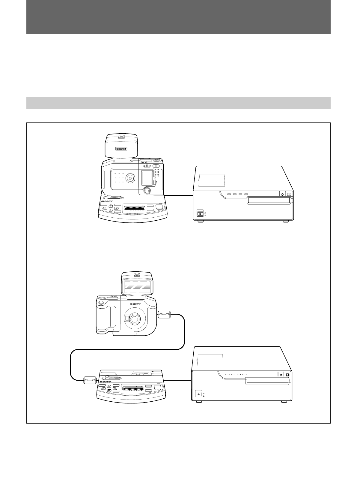
for the UPD-C21X Printer, UPA-C21X Station
and DKC-C21X Digital Still Camera
For the customers in the U.S.A.
This equipment has been tested and found to comply with
the limits for a Class A digital device, pursuant to Part 15 of
the FCC Rules. These limits are designed to provide
reasonable protection against harmful interference when the
equipment is operated in a commercial environment. This
equipment generates, uses, and can radiate radio frequency
energy and, if not installed and used in accordance with the
instruction manual, may cause harmful interference to radio
communications. Operation of this equipment in a residential
area is likely to cause harmful interference in which case the
user will be required to correct the interference at his own
expense.
for the PCS-AC08 AC Power Adaptor
For the customers in the U.S.A.
This equipment has been tested and found to comply with
the limits for a Class B digital device, pursuant to Part 15 of
the FCC Rules. These limits are designed to provide
reasonable protection against harmful interference in a
residential installation. This equipment generates, uses and
can radiate radio frequency energy and, if not installed and
used in accordance with the instructions, may cause harmful
interference to radio communications. However, there is no
guarantee that interference will not occur in a particular
installation. If this equipment does cause harmful
interference to radio or television reception, which can be
determined by turning the equipment off and on, the user is
encouraged to try to correct the interference by one or more
of the following measures:
- Reorient or relocate the receiving antenna.
- Increase the separation between the equipment and
receiver.
- Connect the equipment into an outlet on a circuit different
from that to which the receiver is connected.
- Consult the dealer or an experienced radio/TV technician
for help.
English
You are cautioned that any changes or modifications not
expressly approved in this manual could void your authority
to operate this equipment.
This device requires shielded interface cables to comply with
FCC emission limits.
for the DKC-C21X Digital Still Camera
CAUTION
Danger of explosion if the battery is incorrectly replaced.
Replace only with the same or equivalent type recommended
by the manufacturer. Dispose of used batteries according to
the manufacturer’s instructions.
Voor de Klanten in Nederland
• Dit apparaat bevat een MnO2-Li batterij voor memory back-
up.
• De batterij voor memory back-up van het geheugen is
bevestigd in de batterijhouder van de camera.
• Raadpleeg uw leverancier over de verwijdering van de
batterij op het moment dat u het apparaat bij einde
levensduur afdankt.
• Gooi de batterij niet weg, maar lever hem in als KCA.
• Bij dit produkt zijn batterijen geleverd. Wanneer deze leeg
zijn, moet u ze niet weggooien maar inleveren als KCA.
for the UPC-C21X Printer
WARNING
THIS APPARATUS MUST BE EARTHED

3
System Overview............................................................... 4
System Configuration .............................................................4
Printouts that Can Be Made with This System .......................5
Precautions ........................................................................ 7
Safety ......................................................................................7
Installation...............................................................................8
Operation.................................................................................9
Cleaning ..................................................................................9
Locations of Parts ........................................................... 10
Camera ..................................................................................10
Station ...................................................................................13
Printer....................................................................................15
Preparations..................................................................... 17
Preparation of Printer ............................................................17
Connections...........................................................................25
Preparation of the Camera.....................................................29
Operation.......................................................................... 37
Taking a Picture ....................................................................37
Viewing a Picture..................................................................42
Picture Erasure ......................................................................43
Protecting a Picture ...............................................................46
Printing..................................................................................48
Specifications .................................................................. 52
Troubleshooting .............................................................. 54
Indicators on the Front Panel of the Printer ..........................57
Table of Contents
GB
English

4
System Overview
The Sony UPX-C21 digital printing system is designed to take pictures by
the digital camera and to reproduce them on A6-sized paper in high
resolution (310 dpi) and 256 shades of gray in black and white or in full
color (16,700,000 colors).
System Configuration
Case 1
Case 2
Station
Camera
Printer
Station Printer
Camera
B/W COL
POWER/BUSY
MENU
BATTERY
CHARGE
CAMERA
RELERASE
BW/
COLOR
MULTI
PICTURE
EXEC
PRINT
UPX-C21
1698421
S
O
N
Y
Z
O
O
M
L
E
N
S
/
O
P
T
I
C
A
L
1
.
3
x
F
=
1
2
-
1
5
.
6
m
m
1
:
4
.
0
-
4
.
7
H/S
POWER
PLAY CAMERA
LCD
M,OMITOR
ON
OFF
W
MODE
SET
T
H/S
POWER
ON OFF
B/W COL
POWER/BUSY
MENU
BATTERY
CHARGE
CAMERA
RELERASE
BW/
COLOR
MULTI
PICTURE
EXEC
PRINT
UPX-C21
1698421

5
Printouts that Can Be Made with This System
Printouts of split images
With this system, the following types of printouts can be made:
Model for the U.S.A. and Canada
* Printout of six reduced images is possible only when the UPC-2040A or
UPC-2045 Self-laminating color printing pack is used.
Single portrait Wallets U.S. passport
Printout of Printout of Printout of
four reduced images six reduced images* 16 reduced images

6
Model for the Europe
* Pr intout of six reduced images is possible only when the UPC-2040A or
UPC-2045 Self-laminating color printing pack is used.
Note
Depending on the number of split images on a printout, the ratio between
the height and width of an image may differ.
Color-guide printout
When taking color pictures, a color guide for adjustment can be printed.
For details on color-guide printout, refer to the Operating Instructions (Advanced
Operations).
Hue (RGB) adjustment Light intensity (DARK, LIGHT,
GAMMA) adjustment
-
B + 3 : = (0, 0, +3) G – 3 : = (0, –3, 0)
now : = (0, 0, 0)
G + 3 : = (0, +3, 0) B – 3 : = (0, 0, –3)
R – 3 : = (–3, 0, 0) R + 3 : = (+3, 0, 0)
D + 3 : = (+3, 0, 0) L + 3 : = (0, +3, 0) Gm + 3 : = (0, 0, +3)
now : =(0, 0, 0)
D – 3 : = (–3, 0, 0) L – 3 : = (0, –3, 0) Gm – 3 : = (0, 0, –3)
System Overview
Printout of Printout of Printout of
six reduced images* nine reduced images 16 reduced images
Printout of Printout of Printout of
a full-sized image two reduced images four reduced images

7
Precautions
Safety
• Operate the printer and the AC power adaptor using the power source
specified in “Specifications” (pages52 and 53).
• Be careful not to damage the power cable by placing or dropping heavy
objects on it; it is dangerous to use the printer or AC power adaptor with
a damaged power cable.
• If you do not intend to use the printer or AC power adaptor for a long
time, disconnect the power cable.
• Unplug the power cable by grasping the plug, not the cable itself.
• The negligible amount of electric current will flow into the AC power
adaptor as long as the AC power adaptor is plugged into the wall outlet.
• While the AC power adaptor is in use, it gets warm. But this is normal.
• Be sure that nothing metallic comes into contact with the metal parts of
the AC power adaptor or connecting plate. If it does, a short may occur
and the unit may be damaged.
• Always keep the metal contacts of the AC power adaptor clean.
• Do not apply mechanical shock or drop the unit.
• Do not disassemble or convert the unit.
• Do not remove the cover. There is a danger of electric shock from the
internal parts.
• Be careful not to spill water or other liquids on the unit, or to allow
combustible or metallic material to enter the cabinet. If used with foreign
matter in the cabinet, the unit is liable to fail, or present a risk of fire or
electric shock.
• Ventilation holes are provided to prevent the printer from overheating.
Be careful not to obstruct them with other units or by covering the printer
with a cloth etc.
• If the printer malfunctions or if a foreign body falls into the cabinet,
disconnect the power immediately and consult your Sony service facility
or your Sony dealer.
• Do not open the top cover of the printer during printing because of
mechanical hazard. If you do, turn off the power switch first.
• Do not use the supplied connecting cord with any other AC power
adaptor but this unit. The supplied connecting cord operates normally
only when used with the supplied AC power adaptor.

8
Installation
•Avoid placing the printer or camera in a location subject to:
— mechanical vibration
— high humidity
— excessive dust
— where it is exposed to rain
— direct or excessive sunlight
— extremely high or low temperatures
— close to sources of strong magnetism
— close to sources of powerful electromagnetic radiation, such as radios
or TV transmitters
•Do not use other electronic equipment near the printer. It will not work
properly in strong electromagnetic fields.
•Do not place a heavy object such as a monitor on the printer.
•Keep the AC power adaptor away from AM receivers, because it will
disturb AM reception.
Condensation
•If the printer is subject to wide and sudden changes in temperature, such
as when it is moved from a cold room to a warm room or when it is left in
a room with a heater that tends to produce large amounts of moisture,
condensation may form inside the printer. In such cases the printer will
probably not work properly, and may even develop a fault if you persist
in using it. If condensation forms, turn off the power and leave the
printer to stand for at least one hour.
•If the printing pack is subjected to wide and sudden changes in
temperature, condensation may form on the ink ribbon or paper. This
will cause the printer to malfunction. Also, if the printing pack is used in
this state, spots are likely to appear on the printout. Therefore, avoid
storing the printing pack in locations subject to wide and sudden changes
of temperature.
•To store a half-used printing pack, replace it in its original packing and
reseal the package. If possible, keep the sealed printing pack in a cool,
dark location. To subsequently use the printing pack, place it, in its
sealed package, in a warm room for several hours. Doing so prevents
condensation from forming when the printing pack is removed from its
package.
Location
To prevent internal heat built-up, leave enough room around the printer for
air to circulate through the vents on the left hand side of the cabinet.
Precautions

9
On transportation
• Do not transport the printer with the supplied accessories. Doing so may
cause malfunction.
• Retain the original carton and packing materials in case you have to
transport the unit in the future.
Operation
Test shooting
Before shooting, you should always take a few test shots and review them
to see that the camera is functioning normally.
Copyright laws
You may take pictures for your personal enjoyment with this digital still
camera. However, it is illegal to take pictures of items protected by
copyright laws without the permission of the copyright owner. Keep this
in mind when shooting in concerts, shows and exhibitions, etc. —many of
the items on display are protected by copyrights.
Cleaning
• Clean the cabinet, panel and controls with a soft dry cloth, or a soft cloth
lightly moistened with a mild detergent solution. Do not use any type of
solvent, such as alcohol or benzine, which may damage the finish.
• Use a blower to remove dust from the lens.

10
Locations of Parts
For details, see the pages shown in parentheses.
Camera
Front
1Release button (37)
Press to take a picture shown on the display and record
it in the camera memory.
2Strobe shoe (Refer to the Operating Instructions
(Advanced Operations).)
Attach an external strobe. When an external clip-on
strobe is attached, the strobe will light synchronized
with shutter operation.
3Strobe (37)
Lights according to the selection made with the flash
mode button.
4FLASH jack (Refer to the Operating
Instructions (Advanced Operations).)
Connect a cord from an external strobe.
5VIDEO OUT jack (RCA phono) (Refer to the
Operating Instructions (Advanced Operations).)
If a video monitor is connected using an optional video
cable, you can view a picture displayed on the LCD on
the monitor’s screen.
6RELEASE jack (minijack) (Refer to the
Operating Instructions (Advanced Operations).)
Connect an optional remote release.
7RS-232C jack (minijack) (28)
To use the camera far from the station, connect to the
CAMERA jack of the station using the supplied
connecting cable.
8DC8.4V IN jack (26)
Connect an optional AC power adaptor. The power is
supplied to the camera.
9Lens (f = 12 to 15.6 mm, f-4 to f-4.7)
Auto focus lens.
0Viewfinder (39)
You can see the subject through the viewfinder and
can shoot a picture without using the LCD monitor.
H/S
2
3
4
5
6
7
8
09
1
VIDEO OUT
FLASH
RELEASE
RS-232C
DC8.4V IN
OFF
POWER
ON
S
O
N
Y
Z
O
O
M
L
E
N
S
/
O
P
T
I
C
A
L
1
.
3
x
F
=
1
2
-
1
5
.
6
m
m
1
:
4
.
0
-
4
.
7

11
Rear
1Flash mode button (Refer to the Operating
Instructions (Advanced Operations).)
Selects the flash mode. Each time you press this
button, the setting changes cyclically.
A:The lighting conditions are detected
automatically by prelighting (automatic
photometry function), and the optimum shutter
speed is selected. If necessary, the built-in strobe
lights at the optimum level.
:The built-in strobe always lights at the optimum
level determined by prelighting. The shutter
speed is fixed at 1/250 second, and exposure is
controlled automatically.
E: The built-in strobe always lights. The shutter
speed is fixed at 1/250 second, and exposure is
controlled automatically for a distance of 1.2
meters between the subject and the lens. This
distance is recomended for shooting with the
built-in and external strobes.
:The built-in strobe does not light. The optimum
shutter speed is selected by automatically
detecting the lighting conditions.
E: The built-in strobe does not light, but only the
external strobe lights. The shutter speed is fixed
at 1/250 second.
:The redeye effect that may occur in flash
shooting is reduced by prelighting several times.
Other operations are the same as with A.
2H/S (picture resolution mode) button (Refer to
the Operating Instructions (for Advanced
Operations).)
Selects the picture quality. Each time you press the
button, the setting changes cyclically.
S: High-resolution mode (640 ×480).
Up to 30 pictures can be taken.
Hi1: Super-high-resolution 1 mode (1280 ×960).
Five or more pictures can be taken.
Hi2: Super-high-resolution 2 mode (1280 ×960).
Ten or more pictures can be taken.
H/S
PLAY CAMERA
LCD
MONITOR
ON
OFF
W
MODE
SET
T
POWER
OFF ON
1
2
3
4
5
6
7
8
qa 0
qs
9
qf
qd

12
3Operation display
When the POWER switch is set to ON, the operation
mode or setting status appears.
4Power switch (37, 42)
Turns the power to the camera ON or OFF.
5Zoom lever (Refer to the Operating Instructions
(Advanced Operations).)
Adjusts the framing of the picture.
T: For a telephoto picture
W: For a wide picture
6PLAY/CAMERA switch (37, 42, 43, 46)
PLAY: To see pictures stored in the camera’s
memory.
CAMERA: To take pictures. The standby lamp
lights or flashes in green.
7Liquid-crystal display (LCD)
When the LCD MONITOR switch is set to ON, and
when the PLAY/CAMERA switch is set to CAMERA,
the scene picked up by the lens appears.
When the PLAY/CAMERA switch is set to PLAY, the
picture stored in memory appears independent of the
setting of the LCD MONITOR switch.
When the camera is connected to the station, no
picture is displayed during communication between
the camera and station.
When you press MODE of the mode button, the mode
screen appears.
For details on the mode screen, see “Mode button.”
8LCD MONITOR switch (37, 39)
For turning the LCD ON or OFF when the PLAY/
CAMERA switch is set to CAMERA.
9Battery compartment lid (29)
Insert the lithium ion batteries (large and small,
supplied), and close the lid.
0Mode button (42, 43, 46)
Lightly press the MODE, SET, bor Bside of the
button, and the following action is obtained.
MODE: Each time you press this side, the mode
displayed on the LCD changes cyclically.
When the PLAY/CAMERA switch is set to
PLAY, it changes as follows: no indication t
MULTI (multiple screen) tPROTECT t
ERASE tSET UP.
When the PLAY/CAMERA switch is set to
CAMERA, it changes as follows: no indication
tAUTO/MAN tEXPOSURE t
APERTURE tWHITE BALANCE.
To cancel a selection made by pressing bor B, or
to cancel an operation in progress, press this side.
SET: An item selected by pressing MODE, b, or B
of the mode button is registered.
b, B: A picture to display, erase or protect is set.
qa Metal contacts
For connection with the station. Always keep them
clean. If they become dirty, clean them with a cotton
swab, etc.
Locations of Parts
Picture resolution mode
Flash mode
Redeye reduction
Battery indicator Remaining number
of pictures
Flash mode
Protect mark
(The current picture is protected.)
Picture number
(The number of the
current picture)
Mode display
MULTI: To select nine-picture multiple display
PROTECT: To set or release the protection of
a picture
ERASE: To erase a picture or pictures
SET UP: To set time and day, guideline, and
power saving
MULTI
Hi-1 01
Resolution
(Resolution of the
current picture)

13
qs Tripod screw hole (36)
Used to attach the camera to the tripod. A quick shoe
can be also attached.
qd Standby lamp (37)
The lamp is lit or flashing to indicate the following
conditions when the PLAY/CAMERA switch is set to
CAMERA.
Flashing in red: Preparing for recording, charging
the flash, storing the data (recording is disabled).
Lit in red: Memory full
Flashing in green: Manual setting for exposure, iris
or white balance
Lit in green: Standby for recording
Station
1Camera attachment part (27)
Attach the camera here.
2Metal contacts
For connection with the camera. Always keep them
clean. If they become dirty, clean them with a cotton
swab, etc.
3POWER/BUSY lamp (48)
Lights in green when the connected printer is turned
on. Blinks in red while image data is being transmitted
from the camera to the station. Do not remove the
camera from the station while this lamp is blinking in
red.
qf qg 12
qs
qd
3
4
5
6
7
8
9
0
qa
PRINTER DC IN
CAMERA
RELERASE
B/W COL
POWER/BUSY
MENU BATTERY
CHARGE BW/
COLOR
SPLIT
EXEC
PRINT
UPX-C21
1698421
CAMERA
qf Viewfinder (39)
You can see the subject through the viewfinder and
can shoot a picture without using the LCD monitor.

14
Locations of Parts
4PRINT button (49)
Press to print the image selected on the camera.
5SPLIT button (48)
Select the type of printout: a full-sized image or a split
reduced-image printout.
6B/W COLOR button (48)
Select B/W (black and white) or COL (color) for a
printout.
7Liquid-crystal display (LCD) (48)
Displays adjustment items in the menu operation and
settings of the B/W COLOR and SPLIT buttons.
8BATTERY CHARGE button (31)
Press to charge the large battery installed in the
camera.
9EXEC (execute) button (49, 50)
Press to store the values set in the menu operation.
0Cursor keys (49, 50)
Use during the menu operation.
qa MENU button (49, 50)
Press to enter menu operation. Press again to return to
the normal display.
qs CAMERA RELEASE lever (27)
Slide to the left to detach the camera.
qd CAMERA connector (minijack) (28)
To use the camera far from the station, connect to the
RS-232C connector of the camera.
qf PRINTER connector (D-sub 25-pin) (26)
Connect to the station connector of the printer.
qg DC IN connector (25)
To supply DC power to the station, connect the AC
power adaptor (supplied).

15
9Front panel
Pull the top on the front door toward you to open it.
Opening the front panel reveals the ink ribbon
cartridge, paper tray and paper cover.
When the front panel is open
AInk ribbon cartridge (17)
Insert the ink ribbon cartridge.
BPaper cover (22)
Paper is ejected onto this cover.
CPaper tray (20, 23)
Load paper into this tray.
Printer
Front panel
A
C
B
1!POWER switch (48)
Press to switch the unit on or off.
2Top cover
Only in case the paper has jammed inside the top
cover, open the top cover to remove a jammed paper.
3PRINT indicator (48, 57)
Lights while printing.
4ALARM indicator (48, 57)
Lights in case of paper jamming or occurrence of any
other problem.
5RIBBON indicator (48, 57)
Lights when a problem for ink ribbon cartridge occurs.
6PAPER indicator (48, 57)
Lights when a problem for paper occurs.
7STOP button
Press to stop printing midway.
8PRINT button
Press to reprint the image stored in the memory of the
printer.

16
-AC IN
Rear panel
1Station connector (26)
Connect the interface cable of the station.
2AC IN connector (25)
Used to connect the printer to a wall outlet with the
supplied power cord.
Locations of Parts

17
Preparations
Preparation of Printer
Here are described the following operations that must be made prior to
starting printing.
• Loading an ink ribbon cartridge, a component of an optional printing
pack (see the below)
• Loading paper and the paper cover (see page 20)
Once the above operations have been completed, there should be no need
to repeat them during routine printing. Perform them only when
absolutely necessary.
Loading an ink ribbon cartridge
To make printouts, an ink ribbon cartridge and paper (which are
compatible) must be loaded. (see “Printing pack and paper tray” page 23)
Notes
• Use only ink ribbon cartridge and paper that are designed for use with
this printer. Failing to do so is likely to result in unsatisfactory printing
or malfunctions.
• When replacing the ink ribbon cartridge, it is not required to turn off the
power. Turning off the power will cause the image stored in the memory
to be lost.
1Open the front panel by pulling the front panel top toward you.
(Continue to next page)

18
Preparations
2Remove the ink ribbon cartridge by pushing the ink ribbon cartridge
itself.
The ink ribbon cartridge pops out.
When you use the printer first, this operation is not required.
Note
Never put your hand into the ink ribbon compartment. The thermal head
becomes very hot. You may burn yourself if you touch it.

19
3Remove any slack from the ink ribbon.
If the ribbon is left slack, it may be damaged when inserted.
4Insert the ink ribbon cartridge firmly until it stops.
5Close the front panel.
Wind the spool until the not-used
point comes to the right-end.

20
Preparations
Notes
When using ink ribbon cartridge
•Once an ink ribbon cartridge has been completely used, replace it. Ink
ribbon cartridges are not reusable.
•Do not touch the ink ribbon cartridge or place it in a dusty location.
Finger prints or dust on the ink ribbon will result in imperfect printing or
malfunction of the head.
When storing ink ribbon cartridge
•Avoid placing the ink ribbon in a location subject to:
—high temperatures
—high humidity
—excessive dust
—direct sunlight
•Store a partially used ink ribbon cartridge in its original packaging.
If your ink ribbon should tear
Repair the tear with transparent tape. There should be no problem with
using the remaining portion of the ribbon.
Loading the paper and paper cover
To load paper, follow the procedure below.
Use the paper tray with appropriate paper size.
Notes
•Use only ink ribbon cartridge and paper that are designed for use with
this printer. Failing to do so is likely to result in unsatisfactory printing
or malfunctions.
•When replacing paper trays or reloading the paper, it is not required to
turn off the power. Turning off the power will cause the image stored in
the memory to be lost.
1Open the front panel by pulling the front panel top towards you.
2Push the part marked with PUSH on the paper tray. The paper tray
pops out.
Turn the spool in the direction of the arrow
to remove any slack until the transparent
tape cannot be seen.
Transparent tape
Table of contents
Languages:
Other Sony Printer manuals

Sony
Sony UP-960 User manual

Sony
Sony UP-D71XR User manual

Sony
Sony UPD-X100 User manual

Sony
Sony UPX-C300 User manual

Sony
Sony UP-890CE User manual

Sony
Sony SpectaProof UP-D9500 User manual

Sony
Sony UP-DR80MD User manual

Sony
Sony UP-21MD User manual

Sony
Sony DPP-FP97 User manual

Sony
Sony SpectaProof UP-D9500 User manual

Sony
Sony SnapLab UP-CR15L Guide

Sony
Sony UP-CX2 User manual

Sony
Sony DPP-SV88 User manual

Sony
Sony UP-2300 User manual

Sony
Sony DPP-FP55 User manual

Sony
Sony S-Frame DPP-F800 User manual

Sony
Sony DPP-EX50 User manual

Sony
Sony DPP-M55 Marketing User manual

Sony
Sony UP-DR150 User manual

Sony
Sony UPX-C200 User manual