Sony BRIGHTERA VPL-FH30 User manual

4-186-250-14 (1)
© 2010 Sony Corporation
Data
Projector
Operating Instructions
Before operating the unit, please read this manual and supplied Quick Reference Manual
thoroughly and retain it for future reference.
VPL-FH30
VPL-FX35/FX30
Not all models are available in all countries and area. Please check
with your local Sony Authorized Dealer.

2Table of Contents
Table of Contents
Overview
Location and Function of Controls .... 3
Main Unit ..................................... 3
Connector Panel ........................... 4
Remote Commander and Control
Panel .......................................... 5
Preparation
Connecting the Projector ................... 8
Connecting a Computer ................ 8
Connecting a Video Equipment ... 9
Connecting an External Monitor and
Audio Equipment .................... 11
Projecting/Adjusting an
Image
Projecting an Image ......................... 12
Adjusting the Focus, Size, and
Position of the Projected
image ....................................... 13
Turning Off the Power ................ 14
Adjustments and Settings
Using a Menu
Using a MENU ................................ 15
The Picture Menu ............................. 16
The Screen Menu ............................. 18
The Function Menu .......................... 22
The Operation Menu ........................ 23
The Connection/Power Menu .......... 24
The Installation Menu ...................... 25
The Information Menu ..................... 26
Network
Using Network Features ...................27
Displaying the Control Window of
the Projector with a Web
Browser ...................................27
Confirming the Information
regarding the Projector ............28
Operating the Projector from a
Computer .................................28
Using the e-mail report
Function ...................................28
Others
Indicators ..........................................30
Messages List ...................................31
Troubleshooting ................................32
Replacing the Lamp ..........................34
Cleaning the Air Filter ......................36
Removing/Attaching the Projection
Lens ...............................................37
Removing ....................................37
Attaching .....................................37
Attaching the Projection Lens
Adapter to the Projection
Lens .........................................37
Specifications ...................................39
Projection Distance and Lens Shift
Range ............................................47
Dimensions .......................................51
Index .................................................54

3
Location and Function of Controls
Overview
BOverview
Location and Function of Controls
aLens (page 37)
bFocus ring (page 13)
cZoom lever (page 13)
dLens shift dial (page 13)
eFront panel (page 37)
fRear panel (pages 34, 36)
gVentilation holes (intake)
hVentilation holes (exhaust)
Do not place anything near the ventilation
holes as this may cause internal heat
buildup. Do not place your hand near the
ventilation holes and the circumference as
this may cause injury.
iON/STANDBY indicator
(page 30)
jLAMP/COVER indicator
(page 30)
kControl panel (page 5)
lConnector panel (page 4)
mRemote control detector
The remote control detectors are located
at the front and rear of the projector.
nAdjusters (page 13)
oAntitheft lock
Connects to an optional antitheft cable
manufactured by Kensington.
For details, visit Kensington’s web site.
http://www.kensington.com/
pAntitheft bar
Connects to a commercially available
antitheft chain or wire.
Main Unit
8
3q
s
q
f
2
qa qd9q;4 1 4 5
7
qgqh qd
6
Caution

4Location and Function of Controls
Input (pages 8)
aINPUT A
Video: RGB/YPBPRinput connector
(RGB HD VD/YPBPR)
Audio: Audio input connector (AUDIO)
bINPUT B
Video: RGB input connector (RGB)
Audio: Audio input connector (AUDIO)
cINPUT C
Video: DVI-D input connector (DVI-D)
Audio: Audio input connector (AUDIO)
dINPUT D (VPL-FH30 only)
Video: HDMI input connector (HDMI)
Audio: HDMI input connector (HDMI)
eS VIDEO (S VIDEO IN)
Video: S video input connector
Audio: Audio input connector (AUDIO
L [MONO]/R)
fVIDEO (VIDEO IN)
Video: Video input connector
Audio: Audio input connector (AUDIO
L [MONO]/R)
• The audio input connectors of the projector
are for output to external equipment.
Connect external audio equipment to
output an audio (page 11).
• The audio inputs of INPUT B and INPUT C
are shared. The audio inputs of S VIDEO
and VIDEO also are shared.
Output (page 11)
gOUTPUT
Video: Monitor output connector
(MONITOR)
Audio: Audio output connector
(AUDIO)
This connector outputs the projected image or
audio. The image is output as a computer signal
input from the RGB input connector (INPUT
A, INPUT B) or a video signal input from the
YPBPRinput connector (INPUT A).
Others
hRS-232C connector
RS-232C compatible control connector
iLAN connector (page 27)
jCONTROL S input connector
(DC power supply) (CONTROL S
IN PLUG IN POWER)
Connects to the CONTROL S output
connector on the supplied Remote
Commander with a connecting cable
(stereo mini plug (not supplied)) when
using it as a wired Remote Commander.
You do not need to install batteries in the
Remote Commander, as the power is
supplied from this connector.
kAC IN (∼) socket
Connects the supplied AC power cord.
Connector Panel
qa 9
56 1 7 1 7
56 23
8q; 32 4
Notes
Note

5
Location and Function of Controls
Overview
Remote Commander
Control Panel
aTurning on the power/Going to
standby
?(On) key
1(Standby) key
bSelecting an input signal
(page 12)
INPUT key (main unit)
Direct input select keys (Remote
Commander)
VPL-FH30: The E and F keys are not
provided in this projector.
VPL-FX35/FX30: The D, E, and F keys
are not provided in this projector.
cOperating a menu (page 15)
ENTER /V/v/B/b(arrow) keys
MENU key
RETURN key
RESET key
dAdjusting the image (page 13)
FOCUS key
This function is not provided in this
projector.
ZOOM key
This function is not provided in this
projector.
SHIFT key
This function is not provided in this
projector.
ASPECT key (pages 18, 20)
Changes the aspect ratio of the projected
image.
KEYSTONE key
Adjusts the vertical trapezoidal
distortion of the image manually. When
you press this key, the Keystone menu is
displayed. Use the arrow keys (V/v/B/
b) for adjustment.
PATTERN key (page 13)
APA (Auto Pixel Alignment) key*
Automatically adjusts a picture to its
clearest while a signal is input from a
computer. You can cancel the adjustment
by pressing the APA key again while
adjusting.
*Use this key when inputing a computer
signal via the RGB input connector
(INPUT A, INPUT B).
Remote Commander and Control Panel
ONSTANDBY
INPUT
ABC
DE F
VIDEO
MENU
ECO
MODE
S
VIDEO
ENTER
RESETRETURN
SHIFTZOOMFOCUS
ASPECT PATTERN
KEY-
STONE
D ZOOM VOLUME
MUTING
PIC
AUDIO
+
–
+
–
TWIN FREEZEAPA
1 2 3
ID MODE
1
7
2
6
3
4
8
9
5
ECO
MODE
ENTER
MENU INPUT
3126
Note

6Location and Function of Controls
eUsing various functions during
projecting
D ZOOM (Digital Zoom) +/– key*1
Enlarges a portion of the image while
projecting.
1Press the D ZOOM + key to display
the digital zoom icon on the projected
image.
2Press the V/v/B/bkeys to move the
digital zoom icon to the point on the
image you wish to enlarge.
3Press the D ZOOM + key or the D
ZOOM – key repeatedly to change the
enlargement ratio. The image can be
enlarged up to 4 times.
Press the RESET key to restore the
previous image.
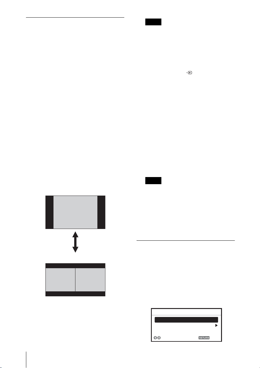
TWIN (Twin Picture) key
(VPL-FH30 only)
You can project the images from two
input signals on the screen as a main
picture and subpicture at the same time.
To switch between one and two pictures,
press the TWIN key on the Remote
Commander.
You can select the image to project to the
main picture.
The subpicture is preset to display the
image from INPUT B.
For details on combinations of input
signals, see “Combinations of Input
Signals” on page 46.
• When displaying a two pictures, the ?
(On) key, 1(standby) key, INPUT key,
and MUTING (PIC) key are available.
• When “Screen Aspect” (page 25) is set
to “4:3,” the two picture function is not
available.
• When displaying a two pictures, the
input signal icon does not appear in
the input select window (page 12).
• Picture settings set for one pictures may
not be reflected as two pictures.
MUTING key
PIC: Cuts off the image. Press again to
restore the image.
AUDIO: Mutes the audio output. Press
again to restore the previous volume.
VOLUME +/– key
For adjusting the volume output from
the audio output connector of the
projector.
FREEZE key*2
Pauses a projected image. Press again to
restore the image.
*1: Use this key when inputting a
computer signal. But it may not be
enabled, depending on the resolution
of the input signal and when
displaying a two pictures (VPL-FH30
only).
*2: Use this key when inputting a
computer signal.
fSetting the energy–saving mode
easily
ECO MODE key
“Lamp Mode,” “Power Saving Mode,”
and “Standby Mode” for energy-saving
can be set easily.
1Press the ECO MODE key to display
the ECO Mode menu.
One picture display
TWIN key
Two pictures display
(A) Main picture (B) Subpicture
Notes
Notes
ECO
User
Sel Back
ECO Mode
ECO Mode Menu

7
Location and Function of Controls
Overview
2Press the V/vkey or ECO MODE key
to select ECO or User mode.
ECO: Sets each mode to the optimum
energy-saving value.
Lamp Mode: Standard
Power Saving Mode: Standby
Standby Mode: Low
(go to step 6)
User: Sets each item of the energy-
saving mode menu as you desire
(go to step 3).
3Select “User” then press the bkey.
The setting items appear.
4Press the V/vkey to select the ECO
Mode item then press the b key or the
ENTER key.
5Press the V/vkey to select the setting
value.
6Press the RETURN key to restore the
previous image.
For details on ECO Mode settings, see
“Lamp Mode” (page 22) on the Function
menu and “Standby Mode” (page 24)
and “Power Saving Mode” (page 24) on
the Connection/Power menu.
Others
gInfrared transmitter
hID MODE 1/2/3 switch (page 23)
Sets an ID mode of the Remote
Commander. If you assign a different ID
number to each projector when multiple
projectors are used, you can control only
the projector with the same ID mode as
that of the Remote Commander.
iCONTROL S output connector
Connects to the CONTROL S input
connector on the projector with a
connecting cable (stereo mini plug (not
supplied)) when using the Remote
Commander as a wired one.
You do not need to install batteries in the
Remote Commander, as the power is
supplied from the projector.
About Remote Commander operation
• Direct the Remote Commander toward the
remote control detector.
• The shorter the distance between the
Remote Commander and the projector is,
the wider the angle within which the
Remote Commander can control the
projector becomes.
• If there is any obstruction between the
Remote Commander and the remote
control detector on the projector, the
projector may not be able to receive
signals from the Remote Commander.
Lamp Mode Standard
Power Saving Mode Off
Standby Mode Standard
Sel Back
User
Set

8Connecting the Projector
BPreparation
Connecting the Projector
• Turn off all equipment before making any connections.
• Use the proper cables for each connection.
• Insert the cable plugs firmly; Loose connections may reduce performance of picture signals or
cause a malfunction. When pulling out a cable, be sure to grip it by the plug, not the cable itself.
• For more information, refer also to the instruction manuals of the equipment you are connecting.
• Use a no-resistance audio cable.
Connection with a computer is explained for each input signal.
INPUT A
For connection when there is some distance between a computer and the projector.
INPUT B
For connecting a computer with an RGB output connector.
It is recommended that you set the resolution of your computer to 1920 × 1200 pixels (VPL-FH30)
or 1024 × 768 pixels (VPL-FX35/FX30) for the external monitor.
Notes
Connecting a Computer
Mini D-sub 15-pin
– BNC cable
(not supplied)
Audio cable
(Stereo mini plug)
(not supplied)
RGB output
connector
Audio output
connector
Computer
Note
Mini D-sub 15-pin
cable
(not supplied)
Audio cable
(Stereo mini plug)
(not supplied)
RGB output
connector
Audio output
connector
Computer

9
Connecting the Projector
Preparation
INPUT C
For connecting a computer with a DVI-D output connector.
INPUT D (VPL-FH30 only)
For connecting a computer with a HDMI output connector.
• The HDMI connector of this projector is not compatible with DSD (Direct Stream Digital) Signal
or CEC (Consumer Electronics Control) Signal.
• Be sure to use the HDMI cable with an HDMI logo.
Connections with a VHS video deck, DVD player, or BD player are explained for each input
signal.
S VIDEO IN
For connecting video equipment with an S-video output connector.
Notes
Connecting a Video Equipment
DVI-D cable
(not supplied)
DVI-D output
connector
Computer
Audio output
connector
Audio cable
(Stereo mini plug)
(not supplied)
INPUT D HDMI
HDMI cable
(not supplied)
HDMI output
connector
Computer
S video cable
(not supplied)
Audio cable (Phone plug × 2) (not supplied)
S video output
connector
Audio output
connector
Video equipment

10 Connecting the Projector
VIDEO IN
For connecting video equipment with a video output connector.
INPUT A
For connection when there is some long distance between the video equipment and projector.
INPUT D (VPL-FH30 only)
For connecting video equipment with a HDMI output connector.
• The HDMI connector of this projector is not compatible with DSD (Direct Stream Digital) Signal
or CEC (Consumer Electronics Control) Signal.
• Be sure to use the HDMI cable with an HDMI logo.
Notes
Video cable
(not supplied)
Audio cable (Phone plug × 2) (not supplied)
Video output
connector
Audio output
connector
Video equipment
Component – BNC
cable (not supplied)
Audio cable (Phone plug
× 2 – stereo mini plug)
(not supplied)
Video equipment
YPBPRoutput
connector
Audio output
connector
INPUT D HDMI
HDMI cable
(not supplied)
Video equipment
HDMI output
connector

11
Connecting the Projector
Preparation
To attach the HDMI cable
Fix the cable to the cable tie holder at the bottom of the projector, using a commercially
available cable tie, as in the illustration.
Use a cable tie of less than 1.9 mm × 3.8 mm in thickness.
OUTPUT
Projected images and input audio can be output to display equipment such as a monitor and
audio equipment such as speakers with a built-in amplifier.
This connector outputs the projected image or audio. The image is output as a computer signal input
from the RGB input connector (INPUT A, INPUT B) or a video signal input from the YPBPRinput
connector (INPUT A).
Connecting an External Monitor and Audio Equipment
Cable tie holder
Cable tie
(commercially
available)
Bottom of the projector
Note
Mini D-sub 15-
pin cable
(not supplied)
RGB input
connector
Display equipment
Audio input
connector
Audio cable
(stereo mini plug)
(not supplied)
Audio equipment

12 Projecting an Image
BProjecting/Adjusting an Image
Projecting an Image
The size of a projected image depends on the distance between the projector and screen. Install
the projector so that the projected image fits the screen size. For details on projection distances
and projected image sizes, see “Projection Distance and Lens Shift Range” (page 47).
1Plug the AC power cord into a wall
outlet.
2Connect all equipment to the projector
(page 8).
3Turn on the projector.
Press the ?/1key on the main unit or the
?key on the Remote Commander.
4Turn on the connected equipment.
5Select the input source.
Press the INPUT key on the projector to
display the input select window. Press
the INPUT key repeatedly or the V/v
key to select an image to be projected.
The signal icon appears on the right
side in the input select window when a
signal is input.
You can select the input source using
Direct input select keys on the Remote
Commander (page 5).
6Switch your computer to output to
external display by changing your
computer’s setting.
How to switch the computer to output to
the projector varies, depending on the
type of computer.
(Example)
7Adjust the focus, size, and position of
the projected image (page 13).
INPUT
Video
S-Videoo
Input-A
Input-B
Input-C
Input-D
Sel Skip
Input
Computer
Video equipment
Projector
Wall outlet
1
23
5
4
5
6
Input select window
+

13
Projecting an Image
Projecting/Adjusting an Image
Adjusting the tilt of the projector with the adjusters
When the projector is installed on an uneven
surface and the projected position is low, you
can adjust using the adjusters. To correct any
trapezoidal distortion of the projected
image, use the Keystone correction feature
(page 5, 25).
• Be careful not to let the projector down on your fingers.
• Do not push hard on the top of the projector with the adjuster extended.
• Since the Keystone adjustment is an electronic correction, the image may be deteriorated.
Displaying a pattern for adjusting an image
You can display a pattern for adjusting the projected image with the PATTERN key on the
Remote Commander. Press the PATTERN key again to restore the previous image.
Adjusting the Focus, Size, and Position of the Projected image
Focus Size (Zoom) Position (Lens shift)
Notes

14 Projecting an Image
1Press the ?/1key on the main unit or
the 1key on the Remote Commander.
The message appears if you press the ?/
1key on the main unit. Press it again
according to the message.
The fan continues to run for a while to
reduce internal heat.
2Unplug the AC power cord from the
wall outlet.
You may unplug the AC power cord
before the fan stops.
To move the projector just after turning it
off, be sure to wait until the fan stops
before unplugging the AC power cord.
Unplugging the AC power cord before the
fan stops may cause a malfunction.
To erase the confirmation message
The message disappears if you press any key
other than the ?/1key on the main unit or 1
key on the Remote Commander, or if you do
not press any key for a while.
To turn off the power with the key
on the main unit without a
confirmation message being
displayed
Hold the ?/1key on the main unit pressed
for a few seconds.
Turning Off the Power
Note

15
Using a MENU
Adjustments and Settings Using a Menu
BAdjustments and Settings Using a Menu
Using a MENU
The menu displays used for the explanation below may be different depending on the model you are
using.
1Press the MENU key to display the
menu.
2Select the setting menu.
Use the Vor vkey to select the setting
menu then press bor ENTER key.
3Select the setting item.
Use the Vor vkey to select the setting
menu then press bor ENTER key.
To return to the selection screen of the
setting menu, press the Bkey or the
RETURN key.
4Make the setting or adjustment for the
selected item.
Menu operation differs depending on the
setting item. If the next menu window is
displayed, select the item according to
the operations in step 3and then press
the ENTER key to register the setting.
To return to the selection screen of the
setting items, press the Bkey or the
RETURN key. Also, to reset the setting
value of an item to its factory preset
value, press the RESET key during
setting or adjusting.
Using a pop-up menu
Press the V/v/B/bkey to select an item.
Press the ENTER key to register the
setting. The previous screen is restored.
Using the setting menu
Press the Vor vkey to select the item.
Press the ENTER key to register the
setting. The previous screen is restored.
Using the adjustment menu
To increase the number, press the Vor b
key and to decrease the number, press
the vor Bkey. Press the ENTER key to
register the setting. The previous screen
is restored.
5Press the MENU key to clear the
menu.
The menu disappears automatically if no
key is pressed for a while.
Note
Picture Mode Standard
Reset
Contrast 80
Brightness 50
Color 50
Hue 50
Color Temp. Middle
Sharpness 50
Expert Setting
Sel Set Back
Picture
Setting menu
Picture Mode Standard
Reset
Contrast 80
Brightness 50
Color 50
Hue 50
Color Temp. Middle
Sharpness 50
Expert Setting
Sel Set Back
Picture
Setting items
Audio Output Volume
Smart APA Standard
CC Display
Lamp Mode Standard
Lamp Timer Reset
Background Blue
Start Up Image On
Sel Set Back
Function
On
Off
Selecting items
Dynamic
Standard
Presentation
Sel Back
Picture Mode
Adjust Back
Contrast
Min
80 Max

16 The Picture Menu
The Picture Menu
For adjusting the picture for each input signal.
*1: When a computer signal is input, this option is available.
*2: When a video signal is input, this option is available.
*3: When “Picture Mode” is set to the item other than “Presentation,” this option is available.
*4: When a B & W signal is input, this option is not available.
*5: When an analog TV signal is input, this option may not available, depending on the color system.
*6: When a video signal is input, this option is available (VPL-FX35/FX30).
Setting items Description
Picture Mode Dynamic: Emphasizes the contrast to produce a “dynamic” picture.
Standard: Makes the picture be natural and well balanced.
Presentation*1:Makes the picture bright to suit for a presentation.
Reset The picture settings are initialized to their factory preset values.
However, “Picture Mode” and “Custom1,” “Custom2,” and “Custom3” of
“Color Temp.” do not return to the factory preset values.
Contrast The higher the setting, the greater the contrast. The lower the setting, the lower
the contrast.
Brightness The higher the setting, the brighter the picture. The lower the setting, the darker
the picture.
Color*2 *4 The higher the setting, the greater the intensity. The lower the setting, the lower
the intensity.
Hue*2 *4 *5 The higher the setting, the more greenish the picture becomes. The lower the
setting, the more reddish the picture becomes.
Color Temp.*3 High/Middle/Low: The higher the temperature, the more bluish the picture.
The lower the temperature, the more reddish the picture.
Custom1/ Custom2/ Custom3: An adjusted color temperature setting can be
stored for each item.
The factory settings are Custom1: High, Custom2: Middle, Custom3: Low.
Sharpness*6 The higher the setting, the sharper the picture. The lower the setting, the softer
the picture.
Expert Setting
Film
Mode*2 *7
Auto: Precisely reproduces the image from a film source to suit the original
film source. Normally, select this option.
Off: Select this option if the images are rough around the edges when “Auto” is
selected.
Black Level
Adj.
(Adjust) *2
High/Low/Off: Emphasizes dark portions of the projected image to suit your
taste.
Gamma
Mode*1 Graphics: Improves the reproduction of halftones. Photos can be reproduced
in natural tones.
Text: Contrasts black and white. Suitable for images that contain lots of text.
DICOM GSDF Sim.*8:Gamma setting is in accordance with the Grayscale
Standard Display Function (GSDF) of the Digital Imaging and
Communications in Medicine (DICOM) standards.
Notes

17
The Picture Menu
Adjustments and Settings Using a Menu
*7: When a progressive signal is input, this option is not available.
*8: Available when a computer signal is input from the DVI-D input connector (INPUT C) and
HDMI input connector (INPUT D). This projector is not to be used as a device for medical
diagnosis (VPL-FH30).

18 The Screen Menu
The Screen Menu
For adjusting the size, position, and aspect ratio of the projected image for each input signal.
*1: • Note that if the projector is used for profit or for public viewing, modifying the original picture
by switching to the aspect mode may constitute an infringement of the rights of authors or
producers, which are legally protected.
• Depending on the input signal, setting items for aspect ratio or some other setting items cannot
be set in some cases, or changing the aspect ratio setting may have no effect.
• A part of the image may be displayed in black, depending on the setting item.
*2: Available for VPL-FH30 only.
Setting items Description
Aspect*1 Changes the aspect ratio of the projected image. (page 20).
When the
computer
signal is
input
Full1: Displays the image to fit the maximum projected image size without
changing the aspect ratio of the input signal.
Full2: Displays the image to fit the maximum projected image size.
Normal: Displays the image on the center point of the projected image
without changing the resolution of the input signal or enlarging the image.
When the
video signal
is input
4:3: Displays the image to fit the maximum projected image size with an
aspect ratio fixed to 4:3.
16:9: Displays the image to fit the maximum projected image size with an
aspect ratio fixed to 16:9.
Full*2:Displays the image to fit the maximum projected image size.
Zoom: Display the center point of the projected image to zoom.
V Center*2 *3 Adjust the whole projected image by moving up and down on the screen.
As the selected number increases, the screen moves up, and as the selected
number decreases, the projected image moves down.
Vertical Size*2 *3 Reduces or enlarges the image vertically.
The projected image is enlarged as the setting increases and reduced as the
setting decreases. If the subtitle of a movie, etc. cannot be seen, use this
together with “V Center.”
Over Scan*3 On/Off: Hides the outline of the image when set to “On.” Select “On” if
noise appears along the edge of the image.
Adjust Signal*6 Adjusts the image of a computer signal. Use this item if the edge of the
image is cut and reception is bad.
APA*4 *5 Automatically adjusts the projected image to an optimum quality when you
press the ENTER key.
Phase*4 Adjusts the dot phase of the display pixel and the input signal. Set to the
value where looks clearest.
Pitch*4 The higher the setting, the wider the horizontal image elements (pitch). The
lower the setting, the narrower the horizontal image elements (pitch).
Shift*6 H: The higher the setting, the farther right the image is projected on the
screen. The lower the setting, the image farther left.
V: The higher the setting, the farther up the image is projected on the screen.
The lower the setting, the image farther down.
Notes

19
The Screen Menu
Adjustments and Settings Using a Menu
*3: Available when a video signal is input from the YPBPRinput connector (INPUT A), DVI-D input
connector, and HDMI input connector.
*4: Available when a computer signal is input from the RGB input connector (INPUT A, INPUT B).
*5: If the projected image includes large amount of black portion around it, the APA function will
not work properly and a part of the image may not be displayed on the screen and also optimum
image cannot be obtained, depending on the type of input signal. In this case, adjust the “Phase,”
“Pitch,” and “Shift” items manually.
*6: Available when a computer signal is input from the RGB input connector (INPUT A, INPUT
B) or a video signal is input from the YPBPRinput connector (INPUT A). This option is available
only when “Aspect” is set to “Zoom.”

20 The Screen Menu
Aspect
VPL-FH30
*1: If you select “Normal,” the image is
projected in the same resolution as the
input signal without changing the aspect
ratio of the original image.
*2: If you select “Full2,” the image is projected
to fit the projected image size, regardless
of the aspect ratio of the image.
*3: Depending on the input signal, the
projected image may be projected as
illustrated below. In this a case, select
“16:9.”
*4: Depending on the input signal, the image
may be projected as illustrated below. In
this a case, select “Zoom.”
*5: If you select “Full,” the image is projected
to fit the projected image size, regardless
of the aspect ratio of the image.
Input signal Recommended
setting value and
projected image
Computer signal
(4:3) (Full1)*1 *2
(16:9) (Full1)*1 *2
(16:10) (Full1)*1
Video signal
(4:3) (4:3)*3 *5
(16:9) (16:9)*4 *5
Other manuals for BRIGHTERA VPL-FH30
5
This manual suits for next models
6
Table of contents
Other Sony Projector manuals

Sony
Sony HDMI VPL-FE40L User manual

Sony
Sony VPL-DX131 User manual

Sony
Sony VPL-PX31 User manual

Sony
Sony VPLCX275 Service manual

Sony
Sony VPL-CX5 User manual

Sony
Sony Superlite VPL-DS100 User manual

Sony
Sony VPL-S500U User manual

Sony
Sony VPH-G70Q User manual

Sony
Sony VPL-GTZ280 User manual

Sony
Sony VPL-EW5 User manual

Sony
Sony VPL-CX236 User manual

Sony
Sony VPL-VZ1000 User manual

Sony
Sony VPL-VW995ES User manual

Sony
Sony VPL-EW246 User manual

Sony
Sony VPL-CX100 Service manual

Sony
Sony MP-CL1A User guide

Sony
Sony VPL-CS3 User manual

Sony
Sony HDMI VPL-FE40 User manual

Sony
Sony VPL-CS10 User manual

Sony
Sony VPL-CX85 User manual