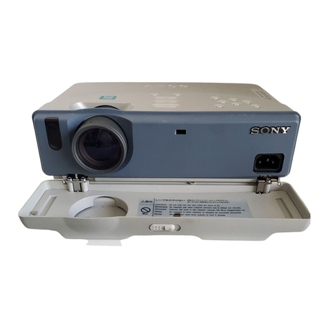
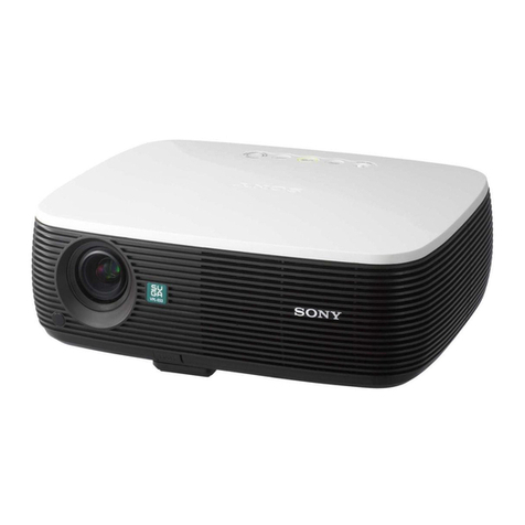
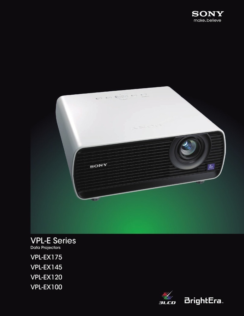
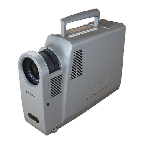
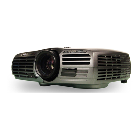
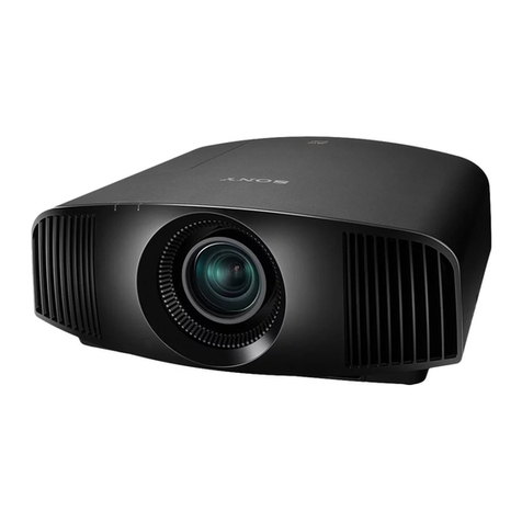
Sony VPL-PX11 User manual

.............. .........
SERVICE MANUAL
.............. .........
MODEL DEST. MODEL DEST.
VPL-PX11 WORLD
VPL-PX11 CHINA
LCD DATA PROJECTOR
VPL-PX11 LCD Data Projector
VPLL-CT10/CW10 Projection Lens (Not Included)
RM-PJM12 Remote Commander
Serial No. 6,500,001 and later
Serial No. 6,000,001 to 6,500,000
VPLL-CT10 WORLD
VPLL-CW10 WORLD
RM-PJM12 WORLD

VPL-PX11
WARNING!!
AN INSULATEDTRANSFORMER SHOULD BE USED DURING
ANY SERVICE TO AVOID POSSIBLE SHOCK HAZARD, BE-
CAUSE OF LIVE CHASSIS.
THE CHASSIS OFTHIS RECEIVER IS DIRECTLY CONNECTED
TO THE AC POWER LINE.
SAFETY-RELATED COMPONENT WARNING !!
COMPONENTS IDENTIFIED BYA !!
!!
!MARKONTHESCHEMATIC
DIAGRAMS, EXPLODEDVIEWS AND INTHE PARTS LIST ARE
CRITICAL TO SAFE OPERATION. REPLACE THESE COMPO-
NENTSWITH SONY PARTSWHOSE PART NUMBERS APPEAR
AS SHOWN IN THIS MANUAL OR IN SUPPLEMENTS PUB-
LISHED BY SONY.
ATTENTION!!
AFIN D’ÉVITER TOUT RISQUE D’ÉLECTROCUTION
PROVENANT D’UN CHÂSSIS SOUS TENSION, UN
TRANSFORMATEUR D’ISOLEMENTDOITETRE UTILISÉ LORS
DE TOUT DÉPANNAGE.
LE CHÂSSIS DE CE RÉCEPTEUR EST DIRECTEMENT
RACCORDÉ Á L’ALIMENTATION SECTEUR.
ATTENTION AUX COMPOSANTS RELATIFS Á LA
SÉCURITÉ!!
LES COMPOSANTS IDENTIFIÉS PAR UNE MAPQUE !!
!!
!SUR
LES SCHÉMAS DE PRINCIPE, LES VUES EXPLOSÉES ET LES
LISTES DE PIECES SONT D’UNE IMPORTANCE CRITIQUE
POUR LA SÉCURITÉ DU FONCTIONNEMENT. NE LES
REMPLACER QUE PAR DES COMPOSANTS SONY DONT LE
NUMÉRO DE PIÈCE EST INDIQUÉ DANS LE PRÉSENT
MANUEL OU DANS DES SUPPLÉMENTS PUBLIÉS PAR SONY.
!WARNING
This manual is intended for qualified service personnel only.
To reduce the risk of electric shock, fire or injury, do not perform any servicing other than that
contained in the operating instructions unless you are qualified to do so. Refer all servicing to
qualified service personnel.
!WARNUNG
Die Anleitung ist nur für qualifiziertes Fachpersonal bestimmt.
Alle Wartungsarbeiten dürfen nur von qualifiziertem Fachpersonal ausgeführt werden. Um die
Gefahr eines elektrischen Schlages, Feuergefahr und Verletzungen zu vermeiden, sind bei
Wartungsarbeiten strikt die Angaben in der Anleitung zu befolgen.Andere als die angegeben
Wartungsarbeiten dürfen nur von Personen ausgeführt werden, die eine spezielle Befähigung
dazu besitzen.
!AVERTISSEMENT
Ce manual est destiné uniquement aux personnes compétentes en charge de l’entretien.Afin
de réduire les risques de décharge électrique, d’incendie ou de blessure n’effectuer que les
réparations indiquées dans le mode d’emploi à moins d’être qualifié pour en effectuer d’autres.
Pour toute réparation faire appel à une personne compétente uniquement.

VPL-PX11 1 (P)
CAUTION
Danger of explosion if battery is incorrectly replaced.
Replace only with the same or equivalent type
recommended by the manufacturer.
Dispose of used batteries according to the
manufacturer’s instructions.
Vorsicht!
Explosionsgefahr bei unsachgemäßem Austausch
der Batterie.
Ersatz nur durch denselben oder einen vom
Hersteller empfohlenen ähnlichen Typ.Entsorgung
gebrauchter Batterien nach Angaben des
Herstellers.
ATTENTION
Il y a danger d’explosion s’il y a remplacement
incorrect de la batterie.
Remplacer uniquement avec une batterie du même
type ou d’un type équivalent recommandé par le
constructeur.
Mettre au rebut les batteries usagées conformément
aux instructions du fabricant.
ADVARSEL!
Lithiumbatteri-Eksplosionsfare ved fejlagtig
håndtering.
Udskiftning må kun ske med batteri
af samme fabrikat og type.
Levér det brugte batteri tilbage til leverandøren.
ADVARSEL
Lithiumbatteri - Eksplosjonsfare.
Ved utskifting benyttes kun batteri som
anbefalt av apparatfabrikanten.
Brukt batteri returneres
apparatleverandøren.
VARNING
Explosionsfara vid felaktigt batteribyte.
Använd samma batterityp eller en likvärdig typ
som rekommenderas av apparattillverkaren.
Kassera använt batteri enligt gällande
föreskrifter.
VAROITUS
Paristo voi räjähtää jos se on virheellisesti
asennettu.
Vaihda paristo ainoastaan laitevalmistajan
suosittelemaan tyyppiin.
Hävitä käytetty paristo valmistajan ohjeiden
mukaisesti.

VPL-PX11
2 (P)
For the customers in the Netherlands
Voor de klanten in Nederland
Dit apparaat bevat een Li-ion batterij voor memory back-
up.
Raadpleeg uw leverancier over de verwijdering van de
batterij op het moment dat u het apparaat bij einde
levensduur afdankt.
Gooi de batterij niet weg. maar lever hem in als KCA.
Bij dit product zijn batterijen geleverd.
Wanneer deze leeg zijn, moet u ze niet
weggooien maar inleveren als KCA.
Für Kunden in Deutschland
Entsorgungshinweis: Bitte werfen Sie nur entladene
Batterien in die Sammelboxen beim Handel oder den
Kommunen. Entladen sind Batterien in der Regel dann,
wenn das Gerät abschaltet und signalisiert “Batterie
leer”oder nach längerer Gebrauchsdauer der Batterien
“nicht mehr einwandfrei funktioniert”. Um
sicherzugehen, kleben Sie die Batteriepole z.B. mit
einem Klebestreifen ab oder geben Sie die Batterien
einzeln in einen Plastikbeutel.
For the customers in the Netherlands
Voor de klanten in Nederland
Bij dit product zijn batterijen geleverd.
Wanneer deze leeg zijn, moet u ze niet
weggooien maar inleveren als KCA.

1
VPL-PX11
Table of Contents
1. Service Informations
1-1. Board Layout...............................................................................................1-1
1-2. Disassembly ................................................................................................1-2
1-2-1. Hood Assembly and Front Assembly Removal .........................1-2
1-2-2. H Board Removal.......................................................................1-3
1-2-3. NF Board Removal ....................................................................1-3
1-2-4. C Board Removal .......................................................................1-4
1-2-5. BB and BA Boards Removal .....................................................1-5
1-2-6. Power Block Removal................................................................1-6
1-2-7. Optics Unit Assembly Removal .................................................1-7
1-2-8. GB Board Removal ....................................................................1-8
1-2-9. QA Board Removal....................................................................1-9
1-2-10. QB Board Removal ..................................................................1-10
1-2-11. F and V Boards Removal .........................................................1-11
1-2-12. Prism Block Assembly and Polarizer Removal .......................1-12
1-2-13. Lamp Assembly Removal ........................................................1-13
1-2-14. Extension Boards and Extension Cables Connection ..............1-14
1-2-15. Main Soft and Pixel Works Soft Writing .................................1-15
1-2-16. Warning on Power Connection ................................................1-16
2. Electrical Adjustments
2-1. Preparations.................................................................................................2-1
2-1-1. Equipment Required...................................................................2-1
2-1-2. How to Enter and Use the Factory Mode ...................................2-1
2-2. V-COM Adjustment....................................................................................2-1
2-3. Adjustment Item Initialize Data ..................................................................2-2
2-4. Service Kowhow .........................................................................................2-7
2-4-1. After Replacing the Prism Block ...............................................2-7
2-4-2. After Replacing the Board .........................................................2-7
2-5. White Balance Adjustment .........................................................................2-8
2-5-1. Signal Level Adjustment ............................................................2-8
2-5-2. White Balance Adjustment ........................................................2-8
2-6. Memory .......................................................................................................2-9
3. Semiconductors ..................................................................................3-1
4. Spare Parts
4-1. Notes on Repair Parts..................................................................................4-1
4-2. Exploded Views ..........................................................................................4-2
4-3. Electrical Parts List ...................................................................................4-10

2VPL-PX11
5. Block Diagrams
Overall ....................................................................................................5-1
BA, BB (1/5), QA (1/2) ............................................................................5-2
BB (2/5), (3/5), NF, QA (2/2), QB ...........................................................5-3
BB (4/5), H, V...........................................................................................5-4
BB (5/5) ....................................................................................................5-5
C ...............................................................................................................5-6
F, G, GB ....................................................................................................5-7
6. Diagrams
6-1. Frame Schematic Diagram ..........................................................................6-2
Frame (1/3) ...............................................................................................6-2
Frame (2/3) ...............................................................................................6-3
Frame (3/3) ...............................................................................................6-4
6-2. Schematic Diagrams and Printed Wiring Boards........................................6-5
Schematic Diagrams
QA (1/2) ....................................................................................................6-6
QA (2/2) ....................................................................................................6-7
QB (1/3) ....................................................................................................6-9
QB (2/3) ..................................................................................................6-10
QB (3/3) ..................................................................................................6-11
BA (1/2) ..................................................................................................6-14
BA (2/2) ..................................................................................................6-15
BB (1/7) ..................................................................................................6-18
BB (2/7) ..................................................................................................6-19
BB (3/7) ..................................................................................................6-20
BB (4/7) ..................................................................................................6-21
BB (5/7) ..................................................................................................6-22
BB (6/7) ..................................................................................................6-23
BB (7/7) ..................................................................................................6-24
C (1/5) ....................................................................................................6-30
C (2/5) ....................................................................................................6-31
C (3/5) ....................................................................................................6-32
C (4/5) ....................................................................................................6-33
C (5/5) ....................................................................................................6-34
F .............................................................................................................6-38
G (1/3) ....................................................................................................6-38
G (2/3) ....................................................................................................6-39
G (3/3) ....................................................................................................6-40
H .............................................................................................................6-41
V .............................................................................................................6-42
NF ...........................................................................................................6-42
GB ...........................................................................................................6-43
3
VPL-PX11
Printed Wiring Boards
QA.............................................................................................................6-5
QB .............................................................................................................6-8
BA ...........................................................................................................6-13
BB ...........................................................................................................6-17
C .............................................................................................................6-28
G .............................................................................................................6-36
F .............................................................................................................6-37
H .............................................................................................................6-41
NF ...........................................................................................................6-42
V .............................................................................................................6-42
GB ...........................................................................................................6-43


1-1
VPL-PX11
Section 1
Service Informations
1-1. Board Layout
C
BA
BB
G
H
QA
QB
F
NF
V
Power block
(Lamp)
GB

1-2 VPL-PX11
1-2. Disassembly
1-2-1. Hood Assembly and Front Assembly Removal
Screw
(B3 x5)
Screw
(B3 x5)
Screw
(B3 x5)
Two screws
(PSW3 x90)
Screw
(PSW3 x90)
Hood assembly
Front assembly
Lens cap (main)
1
2
34
5
6
7
Screw
(B3 x5)
Matching connector
Matching
connector
8
9
H board
CN10

1-3
VPL-PX11
1-2-2. H Board Removal
Hood assembly
Three screws
(B3 x4)
H board 1
2
1-2-3. NF Board Removal
Front assembly
NF board
Adjuster
Screw
(B3 x5)
Screw
(BVTP3 x8)
Three Screws
(BVTP3 x8)
1
2
Plate (FHB)
CN15
34
5
6

1-4 VPL-PX11
1-2-4. C Board Removal
C board
Two screws
(B3 x5) Two screws
(B3 x5)
CN304
CN1207
CN1205
CN1209
CN305
1
2
3

1-5
VPL-PX11
1-2-5. BB and BA Boards Removal
*Remove the C board. (Refer to 1-2-4.)
B block assembly
BB board BA board
Screw
(B3 x5)
Two screws
(B3 x3)
CN801
CN810
CN809 CN811
CN303
CN806
1
2
3
4
Bracket (BB)
5
6
QA board
CN20
QB board
CN31

1-6 VPL-PX11
1-2-6. Power Block Removal
G board
Three screws
Screw
(B3 x5)
Two screws
(B3 x5)
Two screws
(B3 x5)
Two screws
(B3 x5)
CN1101
CN1102
CN1107
1
2
3
4
5
Power block assembly Bracket (BB)
Ballast connector
CN1108
CN1104
Sheet (G)
Sheet (BS)
Bracket (G)
Power block
6
7
8
9
!/
!-
a
a
(B3 x5)
(B3 x8)
(B3 x5)

1-7
VPL-PX11
1-2-7. Optics Unit Assembly Removal
*Remove the C board. (Refer to 1-2-4.)
Two screws
(B3 x8)
Three screws
(B3 x8) Three screws
(B3 x8)
Two screws
(B3 x8)
1
2
3
4
Optics unit asembly
Handle
Matching connector
Matching connector
5
6

1-8 VPL-PX11
1-2-8. GB Board Removal
*Remove the optics unit assembly. (Refer to 1-2-7.)
Two screws
(B3 x5)
3
Five
screws
(B3 x5)
1
CE shield
2
GB board
4

1-9
VPL-PX11
1-2-9. QA Board Removal
*Remove the optics unit assembly. (Refer to 1-2-7.)
6Earth spring
5Video sleeve
1Unit bracket
3Screw
(B3 x5)
2Four screws
4QA board

1-10 VPL-PX11
1-2-10. QB Board Removal
*Remove the QA board. (Refer to 1-2-9.)
Screw
(B3 x5)
Screw
(B3 x5)
Screw
(B3 x5) Two screws
(B3 x5)
Two screws
(B3 x5)
Two screws
(B3 x5)
1
2
3
4
5
6
Four supplied
screws
9
7
8
CN12
CN33
CN30
QB board
assembly
AC inlet
QB board
Plate (CP)0
!-

1-11
VPL-PX11
1-2-11. F and V Boards Removal
*Remove the Power Block. (Refer to 1-2-6.)
*Remove the optics unit assembly. (Refer to 1-2-7.)
Two screws
(B3 x5)
Two screws
(B3 x5)
Screw
(PSW4 x8)
1
2
3
4
5
CN1002 CN16
CN1001
F board
V board
Sheet (F)

1-12 VPL-PX11
1-2-12. Prism Block Assembly and Polarizer Removal
*Remove the optics unit assembly. (Refer to 1-2-7.)
Prism block assembly
Three
screws
Screw
Screw
Out-polarizer (G)
Screw
Out-polarizer (R)
Screw
Out-polarizer (B)
Screw
Two Screws
Screw
1
2
3
4
5
6
7
8
9
!/
!-
!=
![
!]
Polarizer
retainer spring
Polarizer
retainer spring
Polarizer
retainer spring
Polarizer
retainer spring
Polarizer
retainer spring
In-polarizer (G)
In-polarizer (R)
Top cover
Sheet
In-polarizer (B)
Polarizer
retainer spring
!,
!.
@/
!\
!;
!'
@-
@=
@[
Other manuals for VPL-PX11
4
This manual suits for next models
3
Table of contents
Other Sony Projector manuals

Sony
Sony VPL-PX41 User manual

Sony
Sony VPL-HW30ESB User manual

Sony
Sony SXRD SRX-R110 User manual

Sony
Sony VPL-CW275 User manual

Sony
Sony VPH-1001Q User manual

Sony
Sony BRAVIA VPL-VW90ES User manual

Sony
Sony VPL-VW665 Service manual

Sony
Sony BRAVIA VPL-VW60 User manual

Sony
Sony VPL-EW5 User manual

Sony
Sony VPL-CS3 User manual

Sony
Sony VPD-LE100 User manual

Sony
Sony VPL-SW630 User manual

Sony
Sony VPL-CS2 User manual

Sony
Sony MP-CL1 User guide

Sony
Sony SuperLite VPL-CS7 User manual

Sony
Sony VPL-CX11 User manual

Sony
Sony VPL-SW630C User manual

Sony
Sony SuperData VPH-1251Q User manual

Sony
Sony BRIGHTERA VPL-FH30 User manual

Sony
Sony VPL-CX75 User manual