1 (E)
VPL-VW760ES
Table of Contents
Manual Structure
Purpose of this manual............................................................ 3 (E)
Related manuals...................................................................... 3 (E)
Trademarks.............................................................................. 3 (E)
1. Service Overview
1-1. Precautions for Service Personnel.............................1-1 (E)
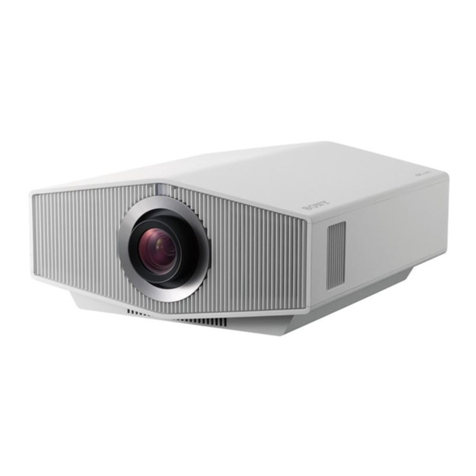
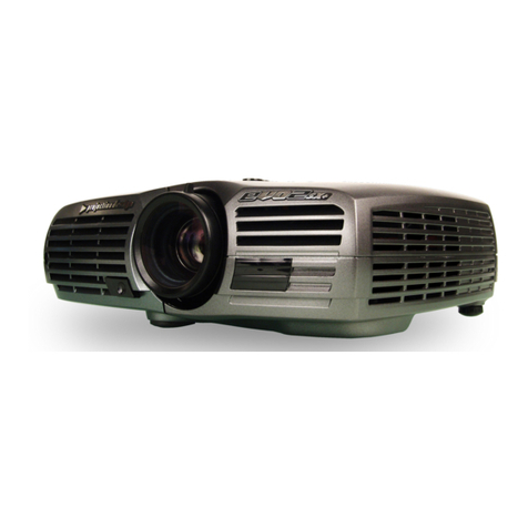
1-2. Appearance Figure ....................................................1-1 (E)
1-3. Locations ...................................................................1-2 (E)
1-3-1. Board Locations...............................................1-2 (E)
1-3-2. Fan Locations................................................... 1-2 (E)
1-4. Tightening Torque .....................................................1-3 (E)
1-5. Disassembly ..............................................................1-4 (E)
1-5-1. Lens Cover Assembly ......................................1-5 (E)
1-5-2. Top Cover Assembly/HA Board/NR Board..... 1-6 (E)
1-5-3. Side Panel (R) Assembly/Side Panel (L) Assembly/
Rear Cabinet Assembly....................................1-7 (E)
1-5-4. Front Panel (R)/HB Board/NF Board ..............1-8 (E)
1-5-5. Front Panel (L)/M Board .................................1-9 (E)
1-5-6. DC Fan (For Power Supply Exhaust) ............1-10 (E)
1-5-7. DC Fan (For Wheel Exhaust) ........................ 1-11 (E)
1-5-8. Light Source Block Assembly/
DC Fan (For LD Intake)/LL Board................1-12 (E)
1-5-9. DC Fan (For Panel)........................................1-13 (E)
1-5-10. DC Fan (For Wheel Intake) ...........................1-14 (E)
1-5-11. DC Fan (For LD Exhaust) .............................1-15 (E)
1-5-12. DC Fan (For PSC and QE Board)..................1-16 (E)
1-5-13. Switching Regulator/DC Fan (For LD Power
Supply Exhaust)/BT Module .........................1-17 (E)
1-5-14. G Board..........................................................1-18 (E)
1-5-15. Optical Block Assembly ................................1-20 (E)
1-5-16. CA Board and CB Board ...............................1-21 (E)
1-5-17. V Board..........................................................1-23 (E)
1-5-18. QE Board .......................................................1-24 (E)
1-5-19. PS Converter..................................................1-25 (E)
1-5-20. Prism Core Assembly ....................................1-26 (E)
1-5-21. Lens Assembly...............................................1-27 (E)
1-6. Maintenance ............................................................1-28 (E)
1-7. Location Information of the Labels......................... 1-38 (E)
1-8. Indicator Display.....................................................1-40 (E)
1-9. Circuit Description ..................................................1-41 (E)
1-9-1. Video Signal Processing System....................1-41 (E)
1-9-2. Signal Generation Board................................ 1-41 (E)
1-9-3. Sensor Board..................................................1-42 (E)
1-9-4. Power Supply Board ......................................1-42 (E)
1-10. Power Cord (VPL-VW760ES Only)....................... 1-42 (E)
1-11. Lead-free Solder......................................................1-43 (E)
2. Electrical Adjustments
2-1. Notes on Servicing ....................................................2-1 (E)
2-2. Preparations...............................................................2-1 (E)
2-2-1. Required Equipment ........................................2-1 (E)
2-2-2. How to Enter the Service Mode....................... 2-2 (E)
2-2-3. How to Enter the Model Name Display
(Shop Demonstration) Mode ...........................2-2 (E)
2-3. Servicing Precautions................................................2-3 (E)
2-3-1. When Replacing the Optical Block
Assembly .........................................................2-3 (E)
2-3-2. When Replacing the Light Source
Unit Assembly .................................................2-3 (E)
2-3-3. When Replacing the Projection Lens...............2-6 (E)
2-3-4. When Replacing the QE Board........................ 2-6 (E)
2-3-5. When Replacing the Board Other
Than the Above................................................2-7 (E)
2-4. White Balance Adjustment........................................2-8 (E)
2-4-1. D93 Mode ........................................................2-8 (E)
2-4-2. D75 Mode ........................................................2-8 (E)
2-4-3. D65 Mode ........................................................2-9 (E)
2-4-4. D55 Mode ........................................................2-9 (E)
2-4-5. Custom Setting.................................................2-9 (E)
2-5. Calibration “save enable” Execution Procedure ....... 2-9 (E)
2-6. Device Adjustment Item Initialize Data ..................2-10 (E)
3. Software Update
3-1. Preparation ................................................................3-1 (E)
3-2. Firmware Update.......................................................3-1 (E)
3-3. Writing of Adjustment Data ...................................... 3-2 (E)
3-4. Reading of Adjustment Data .....................................3-3 (E)

