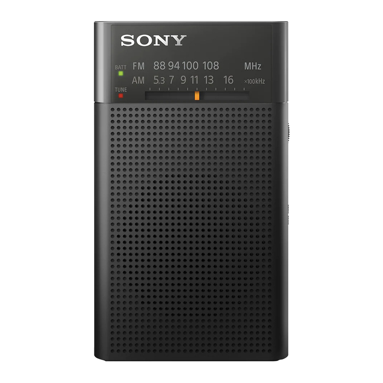
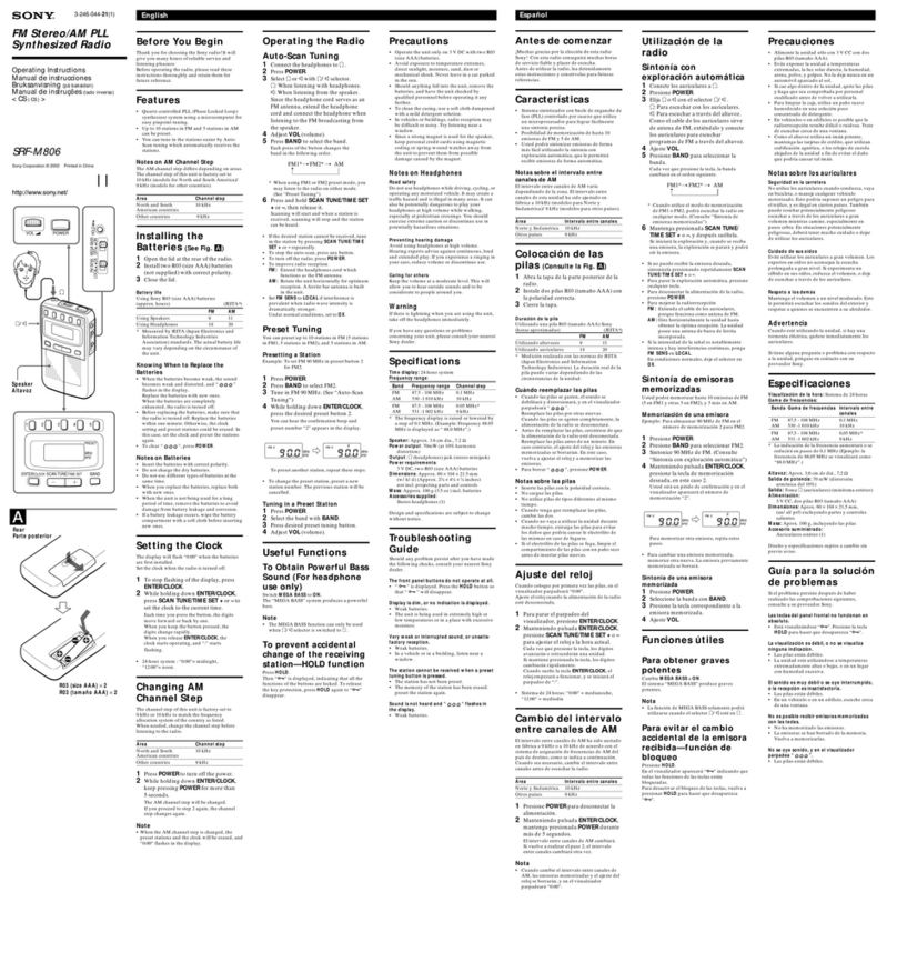
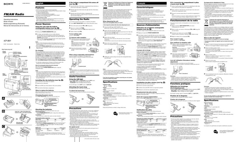
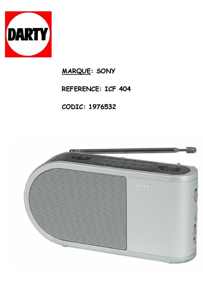
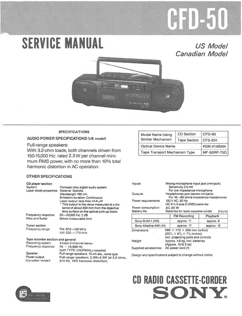
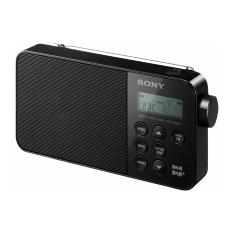
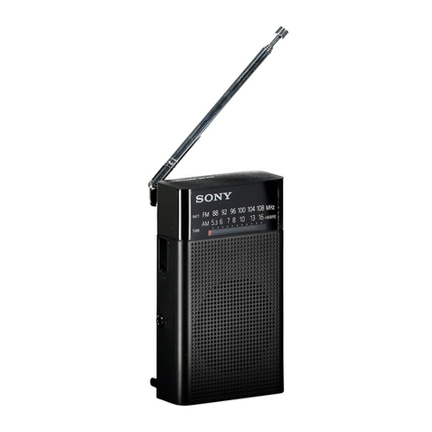
Sony SRF-A100 User manual

www.SteamPoweredRadio.Com
SERVICE
M
ANUAL
US Mo
de
l
Canadian M
ode
l
1!!!11
,1
••••
MICROFILM
S
PE
C
IFIC
ATIONS
Fr
e
quency
range FM
87.6-108
MHz
AM
530-
1,605 k
z
(566-
-1
87
m)
Antenn
as FM:
Teles
copic
antenna or headphone
cord
a enna
AM;
Buil!•i ferrite
ba
ante na
Speaker
App
rox.
7.7
cm
{3!" inches) dla.
Power
output
(at 10
°,
o
harmonic
distort
io
)
Speakers· 360 W---3&0mW
Headp
ones:
40
mW
..-40
mW
Ou
tput
Headphone-
jac
1ste
eo
minijack)
for
32
-
ohm
impedance headphones
Power
requ,rernents
4.5V de. three
s1~e
A ba
teru~s
(I
EG
des
ig a
10 w,
DC
I 4.5V Jae . a
ccepts
· Sony
AC
-1
20
rv
ac ower
ada
pto
(op 1onal) for
use
on
120
V
ac.
60
H~
S
ony
DCC
-127A ca
battery
co
rd
(optional) for use
Ilh
12V car
batte
ry
Dimens
ions
Approx.
22
8 100 •
38
.5
mm
t
/hid)
(9
4 P,u
inc
es)
inc
l. pro
jecting
parts and
co
trols
Weight
ApproY. 62
0g
(1
lb
202
1
i
ncl
. bat eries
Batte
ry
lite
You can
expect
the ollowIng
batte
ies to last
to
r the
indicated
number of hours.
er.
listening four
ho
rs
a day a! a normal
volurne.
t oug e
bu1l
-in spetil ers
or
headphones.
Eveready
0
015
batleries
Eve
ready
No
.
121
5
Heavy
Duty
bat
erl
es
Spea
e
s
16
28
Headp
hones
35
61
(h
our,
FM
STEREO
/AM
STER
EO
RECEIVER
SONY.

www.SteamPoweredRadio.Com
SRF-A100
FEAT
URES
The Sony SRF-A1
00
is
a compact size stereo receiver
which
allows you to en1oy
lis
tening
to
AM
stereo broadcasting
recently put i
nto
service. The rece
iv
er is capable
of
receiv
in
g
for all tour
AM
stereo broadcasti
ng
systems being used.
• AM BANDWIDTH/
FM
SENS (sens1t
1v1
1y)
switch
to
obtain
better recep
ti
on
from each
st
a
tion
under different conditions
• H
ig
h
-qu
al
ity stereo sound from the two bu
il
t-in speakers.
• The one-chip IC developed
by
Sony assures high sensitivity
and high reliabili
ty
.
• Listening
w1tn
optional
stereo headphones 1s possible.
HOW
TO USE
Follow
the
steps
1
to
6 in sequence
to
lune
in
the
st
at
i
on
.
1 POWER switch
Depress
to
turn
on
the
power
(
.:::.
ON).
To turn the receiver
off,
press it
again
to
OFF
).
2
BAND
selector
Select t
he
des
ired band.
FM
ST: For FM reception,
set
it
to
this
pos
ition.
The receiver operates
in
stereo mode
for
FM stereo pro-
gr
am
s
and
will
automatically
switch
to
mono
for monaural
progra
ms
.
AM
ST: For
AM
stereo program reception. The rece
iv
er
ope
r-
ates
in
stereo
mo
de
for
AM
ste
reo programs.
AM:
For
AM
monaural program reception. When
it
is hard
to
hear
th
e
AM
stereo program
due
to
noise,
set
,t
10
this posi-
tion
.
3
AM
ST MODE (
AM
stereo mode)
selector
Set
11
to
the
appropriate
po
s
ition
a
ccording
to
the
AM stereo
broadcasting system
being
used.
A:
For Harris, Mag
nav
ox
or
Motorola
System
8: F
or
Kahn Hazel
tine
System
If
you
do
not
kno
w w
hich
system is being used, you can deter-
mine
the
appropriate
posit
i
on
of
this
selector
by
comparing
the
qua
li
ty
of
the stereo reception
at
each position.
4
AM
BANDWIDTH/FM SENS (sensitivity)
selector
This
2-position
selector
has a
dua
l purpose: the AM BAND-
WIDTH select
or
in AM reception,
and
th
e FM SENS
selector
in
FM reception.
No
rmal
ly
set
this
selec
to
r
to
NORMAULOCA
L.
For
AM
reception, when you want
to
enjoy
th
e AM
st
ereo pro-
gram·s high-qualtty sound, set
it
to WIDE.
For
FM reception, if
th
e re
ception
is interrupted
by
adjacent
station
noise,
set
it
to
DISTANT.
- 2-
5 VOLUME
control
Turn
it
clockw
is
e
lo
gel
sound.
After
tuning.
adjust
the
vo
lume
10
your
preference.
6
TUNING
knob and TUNING indicator
Turn it
to
tune
in
the
desired freq
uency
observing
the
dial
scale. When a
signal
is received,
th
e TUNING
in
dicator
wil
l
lig
ht
up.
O Telescopic antenna
O TONE control
Turn It
to
ad
Just
the
tone
to
your prelerence.
O Carrying strap
attachmen
t
®
DC
IN 4.5V
(e
xternal
power
input)
jack
The
ac
power
adaptor
or
car
baltery
cord
can be connected
to
this 1ack.
G)
PHONES
jack (stereo minijack)
For
li
stening
with
o
ptional
headphones.
lD
Dial scale
~
Battery
compartment
(b
ottom)
)
l
J
www.SteamPoweredRadio.Com
SRF-AlOO I
2
·1
REMOVAL
·ca1
order.
• .
the
numen
R
emove
the
parts InNote:
CABINET REMOVAL
@
rear
cabinet
,,,
SECTION 2
DISASSEMBLy
<:
, '
)
)~/'
./c.:..,
'S-
;
1P
'
~
r---:;
2.6d6
/"';
~
~
main
board
0.
'
I
@
PTP3x
25
I
i .
~
,
z:_r
front
cabinet
7,,
@ 0
Pull
off
knobs.
~
- 4-
)
)

www.SteamPoweredRadio.Com
C
SRF-A100
2-2.
DIAL
CORD
STRINGING
1)
Dial
Cord Preparation
251 mm (9
'/•
inche
s}
2) Dial
Cord
String
ing
dial
drum
0
3)
Pointer
Settin
g
•
Afte
r
the
stringing,
tum
th
e
dial
drum
fully
counterclock
wise.
9-911-
825·52
dial
cord;
0.3
mm
d
ia.
dial d
rum
Set rhe
left
side of t
he
dial
po
inter
at
this
ma
rk.
- 5-
dial
p
ointer
Aft
er
sett
ing
di
al
po
inter,
app
ly a
locking
compound.
0
N
I!)
0
I!)
0
CX)
N
I
- I
r
u
C
0

www.SteamPoweredRadio.Com
SRF-Al
OO
IFM SECTION I
BAND
selector
switch:
FM
ST
FM
SENS
selector
switch
: D1STANT
FM
rf
signal
generacor
OOlµF
sec
ce
lesco,:,ic
SECTION 3
ADJUSTMENTS
VTVM
r-
se
---,t
~.......__"{
l~I
PHONES
22.
5
kH
z
frequency
deviation
by
400
Hz
sign
al
an
cenna l
ead
•
Repeat
the
procedures
in
each
adjustment
seve
ral
times
,
and
the
frequency
cove
rage
and
tracking
adjustments
should
be
finally
done
by
the
trimmer
ca
pa
citors.
I
FM
TRACKING
ADJUSTMENT
Adjust
for
a
maximum
reading
on
VTVM.
86.5
MHz
109.5
MHz
L2
CT2
-
6-
FM
FREQUENCY
COVERAGE
ADJUSTMENT
Adjust
fo
r a
maximum
re:iding
on
VTVM
.
109.5
MHz
86.5 :.!Hz
CT3
L3
)v
)J

www.SteamPoweredRadio.Com
C
RV2
VCO
Adjustmen
t
A)
R
egular
Meth
od
Procedur
e:
FM
rf
stereo signal
gener
ator
I
~
!
0.01
"'
r:-::::-7
<t=====,--i~
Carr
i11r
frequency;
Output
lev
el;
~
ant
enna
terminal
98.1
MHz
1
mV
(60
dB)
frequency
counter
_____
[a
I.
Connect
10
µF
capacitor
between
IC pin (I)
and
R24.
2.
Adjust
RV2
for
76
kHz±
100
Hz
on
the
counter.
B)
Simpl
e Meth
od
Procedure:
I.
T
une
the
set
to
the
FM
stereo
broadcasting
signal.
2.
Tum
RV
2 clockwise
or
counterclockwise
and
memorize
the
lighting-up range
of
the
stereo
lamp.
3.
Secure
R
V2
at
the
center
of
the
lighting-up range
of
both
turns
as
shown
below.
0
I \ / I
'
.....
_
.,,
/
'
.,
.....
_
--
cent
er
of
lighting-up
ranges
l1gh
ting-up range
7-
AM SECTION
I
AM
rf
s
ignal
ge
nera
to
r
30
9'
amplitude
modulation
by
400
Hz signal
P
ut
me
lead-wire
anrenna close
ro
the set.
•
Repeat
the
proc-edure~
in
each
adjustment
several times, and
the
frequency
co1
erage and
tiacking
adjustment<
should
be
finall)
done
bi
th
e
trimmer
cap
a
citors.
BAND
selector
sw
itch:
AM
(mono)
AM
BANDWIDTH switch: WIDE
1,400
kHz
CTI
Ad
just
for
a
maximum
re
adin~
on
vn
·
~1.
TRA
CK
IN
G
ADJUSTMENT
SRF-AlOO

www.SteamPoweredRadio.Com
SR
F-AlOO
AM
IF
ALIGNMENT
.
·
mum
readmg
.
1·
or a maxi
,\dJUSI
on
VTV~t.
45
0
kHz
JFT2
IFT
I
.
~
:~
~l;\j
~n:;.
I
i1
-
8-
VCO
Adjustment
Procedure:
AM
rf
sig
nal
I
~~!:J=
.
===-r--1_0.0T
µ
I---F-
_
__
-____:::c::!-----
:-~
--
.
450kHz
Carrier frequency. o
modulacion
)
Modular
ion:
;2
m V
(9
0
dB
Outpuc
level:
0 ·
0 05 V reading
on
f I 7 ± ·
Adjus
t LS or .
VTVM.

www.SteamPoweredRadio.Com
,-
--
_o_
__
-----
---
-.
I - I
:
---Of)
:
I I
I
I 0
,
__
_-
--
- -
I
I
I
I
I
-
----
--
__
,
VTVM
B
RV1
St
ereo
Distortion
Adjustment
Setting:
AM B
ANDWIDTH
switch:
WIDE
AM
ST
MODE
switch:
B
A)
Regular
Method
Procedure:
SRF-AlOO
AM
ri
stereo signal distortion
generator
~
Carrier frequency:
Output
level:
Modulation:
s
et
1,400
kHz
PHONES
50mV
(94
dB)
15
kHz,
30 %
(AM)
tel
escopic
antenna
lead
I.
Set
the
BAND
switch
to
AM.
meter
~
os
cillosc
ope
B
2.
Adjust
the
output
level
of
the
am
rf
ster
eo
signal
generator
for
dip
point
as
shown
in Fig. 1.
point
m
Fig. 1
3.
Set
the
BAND
switch-to
AM
ST.
4.
Set
the
VOLUME
knob
to
the
mechanical
cente
r.
5.
Adjust
RV
J
for
minimum
reading
on
distortion
meter.
B)
Simple
Method
Adjust
RV
1
to
the
mechanical
center
in
rotation
angle.
-
9-

www.SteamPoweredRadio.Com
:»Kt-AIUU
4-
1.
MOUNTING
DIAGRAMS
Semiconductor
Lead
Layouts
2SA1048-GR
258811
2SC2785
OTC124ES
CX857
;.·
~
o,,
~-1
s,
;:
"'7
~-~I
1
2
'I
(To
p
v,ewl
CX20075
1Marktn,;i s,de
v,aw)
No
te:
TA7331P
TA7342P
CUI~~
o,
Lf1!
dot-
1 , i "
1S1555
1T261
GL9PA21
cathode
anooe
•
o--
:
parts
extra
cted
from
th
e
compo
n
en
t side.
• - :
part
s e
xtracted
fro
m
the
con
du
ctor
si
de
.
• [ ] - :
indi
ca
tes
side
ide
nt
ified
with
pa
rt
nu
mber.
• : B +
pa
tt
ern
•
-•-
: si
gn
al
path
•
__
.,_.
:
L-CH
sig
nal
path
•
-••--+
:R-CH signal p
ath
SEC
TION 4
DIAGRAMS
-10
-
-4--
:::::A!..__....L
__
~B:..___-1-
___
,__---1._
1
2
3
4
5
6
7
8
9
0
IC
D
ORY
8ATT
SI
SE
"
AA
"
!t
EC
OES
IG
NATIO
N R6l
3PCS
,4.5V
•1•1
--
.- - - 4---
J (
I
PHON
ES
I
IL--
--1f--+
--o
I
'
'
,
L----
J2
~
(t)-
~- 0
S4
~~1
ST
\t
OOE
9
I
<l
t :[
A
I
.Cl.
F"\t
TEL
ANT
Il
~
T
l
r
I
l,-
J
1
.so
S3
1~0\\PI
r---
--?
~
I
It>
t
I
j]
Ff
£J
b--
-__
.J
-
.....

www.SteamPoweredRadio.Com
D
2
0
SPI
L-CH
SPEAKER
- +
3LU
O
UTP
UT
,,,.
L
-CH
Y
EL
'-----'
r
_y
K J
E F
10
9
0
- t
G
IC5
SP2
R-CH
SPEAKER
OUTPUT
R-CH
H
IC4
CTI
~
CV
I
82
l
°'{22
I
RV3
lR21
·
ITt\ITTl .
-
~--
5
4
3
LI
AM
FER
RI
TE
·ROD
ANT
-11
-
6
SRF-AlOO
I
I
J
!Cl 4
SRF-J
K
5
[M
AIN
BOARD
.
--
-
-o----
--
---
t:3
5 '
__,.
(
~:~,:
,
11,0
QI
..
:
C3
~ ~ '
G
-L
~ l
0
..SZ,
R25,
~
t2l~
~
--
~
.<,
~
,;.
~23
C28
ov;.:,
~~hf-i
~ C
27
,-- - - - - - - , ~
I-<?
'
··-·'
/;
,- " y
<J'
, t
Q'
,
,;
,oR3
7J
o
~
--- -- -
---{>
04
m· l
m ·
-2
lr1
~
, 09
'-
- - - - - - - ~/ ? \ I
TUNI
NG
I
5,-,
IF
MS
ENS!
: 1$,~NT -
LOCAL
0,
- 2
JA
M
:ANow10TH
I
A
1~
E -
NO/iMaL

www.SteamPoweredRadio.Com
1
2
3
I
4
5
6
I
7
8
9
4-2. SCHEMATIC
DIAGRAM
A B
,1
r
I
"
~
',
'
...
-
I.I
Y.W
;EoR
IT(
-~
,HH
~
~
•o
'
{MAI
N
BOARD
)
s,
-1
Ir•
SE
sS
I
[)15
UN
r
_.,
LOC
.lL
I
"-------~--
-
-'
?
44
'
+
cso
I
,CV
05
2SC2785
AM
ff
,MP
06
2SAI0
48
AM
lf
~MP
C
!.·.
,
:
1i1
:.
.;-
y
-:;:
f)
D
-
13
-
E
F
QI
2SC2785
SLFFE~
l
.lil
P
)3
1S1555
SRF-AlOO
G
02
2SC2
7
85
O•
:s2222
~. ·c
-,
..a
0
.--
---
--+
'(i)_:_ _
'_;.
_3.:.
s·
_~!_Es
_a5
r1
---:.
:-:-
,:~
-;,
-7
--
- T
--
0-•
I_··_·
_ _
C,~
=
;:::
~!t
~
·~~
!.S~,.,,
.J.JO
:,.3
~
.
~
',~
~ I
c____
~ ~ ~
--
"
t1
I
~1·
=
~;.
~(
$,
,,
~r
,:-:i ••
"!:-.::1
,
-.___
· _·
_~
..... • I~
,
1=
1---+-t--
•~
Cl

www.SteamPoweredRadio.Com
SRF-AlOO
H
2
SC27S5
l(
11
ih ~
,J
~
_
:{
1--
-
-+--~~
.(
,
,;,
-----1
~
71
. i
I
- · ;6
~ ~
::::,
,c
;
;,
1
•6•
I
04
2
SA
l048
S~
*'C
""·
N
.:
1)
1
I~
Q8
2SA
l048
A
GC
I
ti.
J
05
GL9
PR2
1
0
0
K
3
7,r
r
··
c~;
Q.C.?:
IC2
TA7342P
flf'
.lil
;:,J
L M N 0
QII
2SB
810
SYi
:
r:H1~
,;
T
:;'i;'.[
L-~'
{!
,,,,
_
_.
,
•...
~
';l I
:-
~\
O)
9TI
•c
~ 1
·-·
~
'-
Q-3_2_S_C-27
_8_
5
__
_
_______
_______
_
...r,;,,_j
J;,, t
IC6
H80148
0A
2-.;:
.. f;.
IJ~
J
I;
•
M
u·1--.::
-
14
-
1r
1 •
:-
3
.,
1 ·
1~
,
r""""-t-
-tt-=--
r
1-(
-
-.
1:
o;.;;;.._
_ _
.
}fff-+
--+-1
\
Q9
,10 2S
C27
85
.c,,F
!.l.
r:,
"
,o:·•" I
\
:,
t

www.SteamPoweredRadio.Com
)
I
p
""
,,J,
Q
i
~~
;!
~::·
£~
0-!~
'
',C
.
I'\
Ot
3P
~~
,
1111
.
:_
,
T
IC5 TA733
1P
A'"
A~
.P
IC
4
TA733
1P
l.
f
/.tf
f
u
. I
••.
..
_
·.:1-
-
f:.
,
l4
;t
-t.1
~
- - - 7
I
.,.
c,
I
:::
.c
I
J.!i\
I
RJ~
I ;
I.:~
..
V
,~~!:
~1
- 1
5-
1
2
3
4
5
6
7
SRF-AlOO
Note
:
•
_.
: signal pa
th
• All
capacitors
are
in
µF
unless
otherw
ise
noted.
pF
:
µµF
50WV
or
less
are
not
indicated
except
for
electrolytics
and
tanta
lums.
• All resi~tors
are
in
ohms,
1/6
W unless
otherwise
noted.
kn:
1000n.
Mn
: 1
000
kn
•
t::.
•:
intern
al
component.
•
c=J
:
ao
1us1m
en
t
for
rep
air.
•
--
: B· bus
• Readings
are
taken
under
no-signal
(detuned)
conditio
ns
with
a
vor-.1
.
no
mark:
FM
I
l:
AM
(( ))
:
common
8 •
Switch
R
ef.
No.
Sw
itch
P
osition
S
1-1
FM
SENS
DISTANT
S1-2
AM
BANDWIDTH WIDE
S2
BAND FM
ST
9
53
PO
WER
OFF
S4
AM
ST
MODE A
No
te: Volt
ages
are measured with a
VOM
(50kf2/V).

www.SteamPoweredRadio.Com
S
RF-AlOO
l
A
(1)
1
2
3
4
5
6
7
8
9
10
SECTION 5
"T
PARTS
LI~
EXPLODEi
VIEWS
oAN_
o_J__E...E_-1.__F
B
~~
~
!
~
~
G
><
.>=
"'
, ....
~
I
~
@ .:U( ,/
~
.
..,,_,.
>
31
..
"
,·
, V ·
-=c
.• . . ·, ~
,-__
·
■
A
B,
C/
,
~"c..~
'"'°_,;
,-<-
·· •
'"-
" /;ndudmg '
/
?1
i~
l
~~
-
.~
1 .
<-
.•.
_~
. 1•
II
~·
. •
'I
, I i
-,
~
tj
~
-~ /
~
i i.
'-
-
~~~
'C • ! I
J!
. ' , . ' v , ' ·~'
..
I
II
•A
I
1.
r~~
~ .·1 :
··
~
-~
·•
L:=..2
;
~~
.
I
~~
I
I
j '
~;;;;;;;;;,-
';PT
I I
l
501
-
16
-
l
1(

www.SteamPoweredRadio.Com
A B C 0 E F
G
(2)
1
©-0~~
'lg
■
A,
B,
CJ
2
" ~ I
18
~
II
3
28
•
I
12
l
v
. / I
~
,..-:')
4
~
/-
'
~~_.,-
--~'::)
'
\~
f
5
I
6
8
: L1
·,
"'
~2
<:,
-
I
I
~
\ !
IC3~
\
~
~
6
X
>.
~
50
3
I :
~·-tii
: I
\
- .,;1~.
27
I
,~?
' '
'1
,I
t)
""",
23
S2
1
I\ _.rc,.
.r.,...-
-
-_J
I
'\
~h-/
3 I
,
1 ~ I
~-
1
1@
5
5
0
04
2
/"'\.,
~
• • •
@)
'0fe
S1
,
JT
9
VR3
J2
I VR4
~
S4
S3
- 17-

www.SteamPoweredRadio.Com
:»K
r-
AIUU
GE
N
ERAL
SECTION
ACCESSORY
&
PAC
K
ING
MATERlAL
No.
Part
No
.
Desc
ri
pt
ion
l 3-701 -999-00
LABEL
,
SERIAL
NUlilER
2 3- 703- 710-0l
STICKER,
SONY
SYMBOL
(12)
3
3-
849-
226
-00
CLOTH
,
UNWEAVED
(25X6X0.5)
!~
;
Pdrt
Ho
. Oescri
pt
ion
3-Sn
-85
4-5I
BELT
,
SHOULDER
72
3-
701-623-00
BAG,
POL
YE
THY
LENE.
73
3-822-524-00
LABEL,
CAUTI
ON
4 3-881-911-00
PULLEY
74
3-891-025-00
BAG,
PROTECT
I
ON
5
3-
883
-428-00
PLATE
,
TERMINAL
(POSITIVE)
6 6
;3
-887-506-00
SHAFT,
TUN
ING
75
3-891-027-00
CASE
~A)
76
3-891-028-00 C
ASE
8)
7 3-888- 156-00
SCREW
8 3-891-001-00
KNOO
, DIAL
9 3-891-002-00
KNOO
77 3-891-047-00
INDIVIDUAL
CARTON
(SLEEVE)
78
3-995-967-22
MANUAL
, l
HSTRUCTI
ON
79
3-995-
967
-
31
(C
anadian)
••.
l'ANUAL,
!NS
TRUCTION
10 3-
891
-003-00
KNOO,
SELECTION
11
3-891-004-00
BUTTON
12
3-
891
-006-00
POINTER
, DIAL
ELE.C
TR
I
CAL
PAR
TS
13 3-891-008-
00
LIO,
BATTERY
CASE
14
3-891-009-00
SPRI
NG
15 3-891-011-00
STOPPER
,
SPEAKER
Ref.No.
Part
No
.
Desc
ri
et
ion
SOI
l-50
1-
222-00
ANTENNA,
TELESCOPIC
16
6
;3
-89
1-
017-00
DRU
M, DIAL
17 3-891-019-41
CABINET,
REAR
18 6
;3
-891-020-00
CHASSIS
502
i l -610-634-00
PC
BOARD
.
MA
!ti
SOJ
6
l-610-635-00
PC
BOARD
,
AH
50
4 i A-3660-445-A
HClJNTED
PCB
(A),
MAIN
19 3-
891
-021-00
SPRING
BPF
l -235-171-00 FILTER,
BAND
PASS
20 3-891-031-00
LJISEL
,
MODEL
NUri!ER
(U
,
CND)
21
3-891-037-00
SHEET
Cl l -161-013-00
CER.Al-1
IC
O.OlMf
10%
C2 1- 161-013-00
CERA'11C
O.OlHF
10
'.t
22
6;
3-
891
-038-00
CASE
{B)
,
SHIELD
23
6;3
-891-039-00
CASE
(C),
SHIELD
24 3-891-040-00
PLATE
,
CONTACT,
ANTENNA
C3
l-101-888-00
CER#t
IC
68PF
5%
C4
1-123
-611-
00
ELECT
lMF
20
%
cs
l-161-013-00
GER.Al-I
IC
O. O
H1F
lOt
25 i
;3
-891-041-00
PLATE
,
SHIELD
C6
1-123-610-00
ELECT
O.
47MF
20%
26
6;3-
891
-042-00
SHEET,
INSULATING
27
3-891-044-00 PIN,
WIRE
C7
l-161-007-00
CERN1IC
o.
003
3'1F
10
%
CB
l-
123-617-
00
ELECT
lOHF
20%
28
7-624-W6-04
ST
OP
RING
3.0,
TYPE
-E
C9
l-161-007-00
CER
AMIC
o.
0033-lf
10:
29
7-682-146-13
SCREW
•P
3XS
30 7-685-152-
14
SCREW
+PTP
3X25
TYPE2
NON-SLIT
ClO
l -123-613-00
ELECT
3.
3MF
20'.t
31
32
33
34
35
36
37
7-685-536-19
SCRBI
t8TP 2.6Xl2
TYP£2
N-S
7-
685
-
538
-
19
SCREW
+
BTP
2.
6X
16
TYPE2
N-S
9-911-825-
52
CORD
, DIAL;0.3rnn DIA
9-911-840-
XX
FOOT
9-911-856-XX
CUSH
ION
4-822-524-
00
LABEL
,
CAUTION
X-3891-006- l
CAB
1
NET,
FRO
NT
NOTE
:
Items
with
no pd
rt
number
and
no
des-
cription
dre
not
stocked because they
dre
seldom required
for
routine
serv
ic
e.
Items marked " • • are
not
stocked
since
they are se
ldom
required
for
routine
service.
Some
delay should
be
antici-
pated wh
en
o
rdering
these
ite
m
s.
Due
to
stancard1zati
on
,
parts
with
part
numbers
(
11
-U.l\-
jM.
-
XX
or ~-:.11~
-~:.
:i-X)
may
be
different
from those
use
d
in
the
set.
If
there are
two
or
more
same
c1rcuftsin
a
set
suc
h
as
a
stereophonic wachine, only
cy
oical
cir
c
uit
parts
may
be
indicated
and
capacitors
and
resistors
in
other
same
cfrcu
i
ts
may
be
omitt
ed.
Cll
1-123-827-00
Cl2 l - 1
6I
-003-00
C13
1-161-003-00
C
l4
l -
13I-347-00
CIS l -
161
-039-00
Cl6
l - 161-013-00
Cl7
l - 123-
661
-00
C2
l 1-102-942-00
C22
1- 102-960-00
C2
3
l-!02-
883-00
C2
4 1- 102-637-00
C2
5 l -123-294-00
C26
l-I61-039-00
C27
l-123-617-00
C28
l
-123-2
98-00
C
29
l -
I23
-356-
00
C3
0 l -123
-617-
00
C
APA
CITORS:
MF
:..,
F,
Pf':~u
f.
~ES
IS
TO
RS
· A
11
res
1
s
to
rs
a
re
in
ohms.
· F :
nonflacr.ldble
COILS
· l'tH :
mH
, UH :
.H
SEM
!CONDUCTORS
In
each
case, U :
,,
for
examp
le:
ELECT
CERIV'I
IC
CER/\MIC
TA
NTALUM
CERA111C
CERN1IC
ELECT
CERN11C
CER/\M
IC
CERIV'I
IC
CERNl!C
ELECT
CERN1IC
ELECT
ELECT
ELECT
ELECT
UA
·•·:
a
A···,
UP
A·•-
:
..
PA
···,
UPC··
·:
..,
PC
,
UPO
••, :
1,1P
D· · ·
-
18
-
220'1F
20
'.t
O.
OOl
SMF
10
'.t
O.
OOlS
MF
10%
lMF
20%
O.
OOlMF
10%
O.OlMF
10'.t
10CMF
20'.t
SPF
O
.S
PF
24PF
s:
27PF
s:
l
2PF
5%
47
MF
20%
O.OOlHF
10%
lOHF
20
%
4
7a
~F
20%
lO
MF
20%
1011F
20%
25V
25V
sov
sov
25V
50V
25V
)
16V
25V
35V
4V
25
V
25V
35V
25V
25V
6.3V
sov
so
v
SOY
sov
6.
3V
25V
16V
6.
3V
16V
16V
)

www.SteamPoweredRadio.Com
SRF
-A
100
(
~
r;
AL
PARTS
ELECTRICAL
PARTS
~
Part
No.
Descri(!tion
I
Ref.No.
Part
No.
Descri
et
ion
C3I
l-123-
616-00
ELECT
4.
7MF
20;;
25V
C76
l-123-661-00
ELECT
10()-lf
20;;
6.
3V
C3
2
l-161-0
17
-00
CERAMIC
O.
022MF
10%
25V
en
l
-12
3-2
9
8-00
ELECT
47o-tf
20%
6.3V
C33
l-123-607-
00
ELECT
O,
lMF
20;;
sov
C78 l -123-298-
00
ELECT
47o-tF
20%
6.JV
C34
1-161-013-00
CERN-I
IC
O.OlMF
10%
25\1
C79
l -12
3-2
98-00
ELECT
47o-tF
20%
6.3V
C35
1-161-013-00
CERN-I
IC
O.OlMF
10%
25V
C80
1-123-298-00
ELE
CT
47~F
20%
6,3V
C36
1-161 -013-00
CERN-I
IC
O.OlMF
10%
25V
CBI
l-161-013-00
CERN-I
IC
O.OlMF
10%
25V
C37
l-161-013
-00
CERNIIC
O,OlMf
10%
25V
C82
l-102-973
-
00
CERAloflC
lOOPf
s;;
SOY
C38
1-123-617-00
ELECT
lOMF
20%
16V
C83
l-123-295-00
ELECT
lOo-tF
20%
6,3V
C39
l-102-973-00
CERA'-IJC
lOO
PF
5%
sov
C84
l-123-617-00
ELECT
lOHF
20J
16V
C40
l-161-015
-00
CEIWo\lC
O.
01
SMF
10%
25V
CBS
l-102-973-00
CERN-I
IC
lOOPF
5J
sov
C41
l-161-015-00
CER.bJ-IJC
O.
Ol5MF
10%
25V
C86
l-102-973-00
CERA"IIC
lOOPF
5%
sov
C42
l-123-616-00
ELECT
4.
7M
F
20;;
25V
C87
l
-12
3-616-
00
ELE
CT
4.
7MF
20%
25V
C43
l-123-616-00
EL
E
CT
4,
7MF
20;;
25V
CF
l
1-5
67
-123
-
00
FILTER,
CERN-IIC
C44
1-123-611-00
ELECT
IMF
20;;
sov
Cf2 1-527-481-00 FI
LTER
,
CERAMIC
C45
l-123
-613-00
ELECT
3.
3M
F
20%
35V
CF3
l
-56
7-097-61
FILTER
,
CER#IIC
CF
4 l-567-097-61 F
lLTER,
CER.AI-IIC
C46
1-130-651-00
FILM
O.OOlHF
5%
lOOV
C47
l-123-380
-00
ELECT
lMF
20%
50V
Dl
8-719-815-5S
DIODE
1S1555
C48
l-
123-
294
-00
ELECT
47MF
20%
6,3V 02 8-719-815-55
OIOOE
151555
03 8-719-81S-55
OJOOE
1S1555
C49
l-123-295-00
ELECT
1001F
20%
6,3V
C5C
l-123-380-00
ELECT
IMF
20');
50V
D4
8-7l9-104-15
OIOOE
1T26l
CSl
l-161-0
13
-00
CERAMIC
O,OlHF
10');
25V
05
8-719
-909-21
DIOOE
GL-9PR21
06 8-719-815-5S
DIODE
1S1555
C52
l-123-318-00
ELECT
33/'IF
20%
16V
07 8-719-815-55
DIODE
1Sl55S
CS3
l-
123-380-00
ELECT
lMF
20%
50V
C54
l -161-021-00
CERAI-IIC
0,
047HF
10%
25V
lCl
8-752
-0
07-SO
IC
CX20075
IC2
8-759-201-14 IC
TA
7342P
css
l-123
-296-
00
ELECT
22(),lf
20%
6.
3V
!CJ
8-759-907-69
IC
CX
-8
57
C56
1-123-611-00
ELECT
IMF
20%
sov
(
C57
l-123-611-00
ELECT
lHF
20%
sov
IC4
8-759-203-31
IC
TA7331P
!
CS
8-759-203
-
31
IC
TA7331P
C58
l-123-611-
00
ELECT
IMF
20%
sov
IC6
l -464-278-00
CI
RCUIT
UNIT
,
AM
PLIFIER
(2CH)(H8Dl480A)
C59
l-123-611-
00
ELECT
lMF
20%
sov
C60
l-161-021-00
CERN-I
IC
0.047HF
10%
25V
IFTl l
-4
04-023-00
COIL, !FT
IFT2
l
-4
04-482-
00
TRANSFORMER,
IF
C61
1-161-021-00
CERM-IIC
0.047MF
10%
25V
C6
2
l-123-612-00
ELECT
2.2MF
20:
50V
Jl
l
-5
07-806-00
JACK,
PHONES
C63
1-123-612-00
ELECT
2.2Mf
20%
sov
J2
1-507-459-
00
JACK.
DC
IN
4.SV
C64
l-123
-295-00
ELECT
1001F
20%
6.
3V
Ll
l-402-042-00
ANTENNA,
FERRITE-ROD
(MIi)
C65
l -102-
973-00
CERIV11C
lOOPF
5%
SDV
L2
1-4S9-435-00
COIL
(WITH
CORE),
FM
RF
C66
l-123-617-00
ELECT
lOMF
20%
16V
L3
l -4
59-
418-00
COIL
(WfTH
CO
RE),
FM
OSC
C67
1-123-295-00
ELECT
!Oil-IF
20%
6
.3
V
L4
1
-4
05-989-00
COI
L,
H,/
DSC
C68
1-131-345-00
TANTALUM
0.47MF
10%
35V
LS l- 40
6-070
-00 C
OIL
,
DSC
C69
l-161
-039-00
CE
RAM
lC
O.OOlMf
10%
2SV
L6
l-409-365-00
COIL,
TRAP
L7 1
-4
08-5
79-0Cl
MICR
O I
N!lU
CTOR
220UH
C70
1-123-295-00
ELECT
lOOMF
20%
6.3V
C
71
l-102-
973-00
CERN11C
IOOPF
5:t
5
0V
QI
8- 729-178-54
TRANSISTOR
2SC2785
C72
l-123-617-00
ELECT
IOMF
20,.
16V
Q2
8- 729-178-54
TRANSISTOR
2S
C2785
Q3
8-729-1
78
-
54
TRANSISTOO
2SC2785
C
73
1-123-295-00
ELECT
10()-IF
20:t
6.JV
C74
1-131-345-
00
TANTALUM
0,
4
7HF
10,-;
35V
Q4
8-
729
-204-83
TRANS!STOO
2SA1048-G
R
C75
1-161-039-
00
CERAMIC
O.
OOlMF
10:t
25V
Q5
8-729-178-54
TRANSISTOO
2SC2785
Q6
8- 729-204-83
TRANS
!S
TOR
2SAI048-
GR
N
OTE:
CAPAC
I
TORS:
Items
with
no
part
number and
no
des
-MF:.,F ,
Pr:~~r.
cr1pt1on
are
not
stocked
because they
r·s
!
STORS
are
selda,,i
required
for
routine
service.
·
All
resistors
are
in
ohms.
It
ems
marked " 6 "
are
not
stoc~ed
since
• F :
no
nflam
able
the
y
are
se
l
dom
required
for
,outine
serv
ice.
Some
delay
should be
ant
ici
-
COILS
pated
whe
n
ordering
these
items.
.
r+IH
:
mH,
UH
:
uH
Due
to
stancardization,
parts
with
p
art
SEMI
CONDUCTORS
{
numbers
(l-~M-Ol~
·
XX
or
l ·
lO~
-L
~O
-
X)
may
be
different
from
those
u
~·d
in
the
Jn each
case,
U :
u,
for
example:
UA
..
-:
u
A·
•
·,
UPA
-
..
uPA
--·
,
UPC
..
,:,
uPC ,
set.
If
the
re
are
two
or
more
same
circuits
io
a
UPO
..
· :
uPD
·
..
set
such as a
stereophonic
ma
chin
e,
only
typical
circuit
parts
may
be
indicated
and
capacitors
and
resistors
in
other
same
circuits
may be
c,mit
ted
.
-
19
-

www.SteamPoweredRadio.Com
SRF-AlOO
ELECTRICAL
PAATS
ELECTRICAL
PARTS
Ref. N
o.
Pac-t
No.
Descri
eu
on !Ref
.N
o,
Part
No.
Descri
et
ion
(
Q7
8-729-900-37
TRANSISTOR
OTC124ES
R49
l -247-815-00
CARBON
220
5%
1/5,/
QB
8-729
-204-83
TRANSISTOR
2SA1048-GR
RS
O l -247-849-00
CARBON
5.6K
s,:
1/&I
Q9
8-729-178-54
TRANSISTOR
2SC2785
R51
l- 247-887-00
CARBON
220K
5%
1/&.
QlO
8
-72
9-178-54
TRANSISTOR
2SC278!>
R52
l -247-847-00
CARBON
4.
7K
si
1/6'.I
Qll
8-729-181-13.
TRANSISTOR
2S8811
R53
l -247-825-00
CARBON
560
s,:
1/fi,/
R54
1-
24
7
-849-0
0
CARBON
5.
6K
5,:
l/6,/
Rl
l -247-823-00
CARBON
470
5%
l/6W
R2
l
-24
7-879-00
CARBON
10()1(
5%
1/6-,1
RSS
1-247-887-00
CARBON
2201(
5%
l/&,/
R3
l-247
-879-00
CARBON
lOOK
s,:
1/fJ,/
R56
1-247
-84
7-
00
CARB
ON
4.
7K
5,:
I/&,/
RS?
1-247-825-00
CARBON
560
5%
1/6\1
RS
1-2
47-867-
0D
CARBON
33K
s,;
1/6\,/
R6
l-247
-847-00
CARBON
4,
7K
5%
1
/6\ol
R58
1-247
-849-
00
CARBON
5.6K
5%
1/&I
R7
l-247-847-00
CARBON
4-
7K
Si
1/6'.(
R59
1-24
7-849-00
CARBON
5.6K
5%
l/0,/
R60
l-
247-831-00
CARBON
lK
s,;
l/&,,
RB
1-247-
87
1-00
CARBON
4
7K
5%
1
/6-,/
R9
l-24
7-855-00
CARBON
lOK
5%
l/6W
R61
l-246-437-00
CARBON
33
5%
1/4,1
RIO
l -247-820-00
CARBON
360
5%
1/(y,/
R62
1-247-879-00
CARBON
lOOK
s,:
1
/611
R63
l -247-879-00
CARB
ON
lOOK
5%
1/611
Rll
l-247-847-00
CARBON
4,
7K
s,;
1/e.l
Rl2
1-24
7-847-00
CARBON
4.
7K
5%
1
/&.I
R64
l-2~7-871-
00
C,6.IU!ON
47K
5,:
1/6',,
Rl3
l-247-847-0
0
CARBON
4.
7K
5%
1/fJ,/
R65
l-247-807-00
CARSON
100
5%
l/5,,' I
R67
l-247-803
-00
CARB
ON
68
5%
1/611
R2l
l-247-827-00
CARBON
680 5,;
1/&.I
R22
l
-24
7-804-00
U~ON
75
1/fM
R68
l- 247-879-00
CAABON
lOOK
5%
1/
&I
R23
1-247-817-00
CARBON
270
5%
l/6W
R69
1-247-879-00
CARBON
lOOK
5%
1/&.I
R70
l -247-871-00
CAAB
ON
47K
5%
1
/6,!.
R24
l-247
-849-00
CAA.'.'ON
5,6K
51
1/fM
R25
1- 247-879-00
CAAE.JN
10()1(
5%
l/6W
R71
l-247-807
-00
CAP.B
ON
100
5%
l / 6,/
R26
l-247-879
-00
CARr.JN
lOOK
5%
1/f},I
R73
l-247-803-00
CARS
ON
68
5%
1/611
R74
l-247-783-00
CAABON
10
5%
1/
6,i
R27
l-247-871-00
CARBON
471,.
s,;
1/e.l
R28
1-247-879-00
CARBON
10
(),(
5%
1/6\1
R75
l -247-783-00
CARBON
10
s,:
1/
6,/
R29
1-247-84
7-00
CARBON
4.
7K
5%
1/6\/
R76
1-247-871-00
CAABOtl
47K
5%
1/S./
R77
1-247-843-00
UllBON
3.3K
5%
l
/S
ft
R30
l-247-835-
00
CARBON
l.
SK
5%
1/611
R78
l -247-855-00
CARBO
N
lOK
5%
11
;;..
R3l
l-247-885-00
CARBON
180K
5%
1/0,/
R79
l-247-8i7-00
CARB
ON
270
!i%
:
~
~
(
R32
1-247-850-0D
CARBON
6.2K
5%
l/6W
Sl
l-554
-222-00
SWITCH,
SLIDE,
FM
SENS/II."
·
SA~J..t!DTH
R33
l -247-849-
00
CARBON
5.
6~
5%
1/6,/ S2 l -554-598-00
SWITCH,
SLIDE,
BAN
D
R34
l
-24
7-853
-0
0
CARBON
8,
21-.
5%
l/~
S3 1-554-358-00
SW
ITCH
,
PUSH,
P0h"£R
R35
l-247-839-0
0
CARBON
2,2K
5%
1/6\1
S4
l-552-370-00
SWITCH,
SUD£,
Nii
ST
MODE
R35
1-247-875-00
CARBON
68K
5":.
1/6\1
vc
l - 151-434-00
C,4.P,
TUNlt«i,
POLYETHYLENE
R3
7
l-247-831-00
CARBON
lK
5%
l
/&,1
R38
l-247-853-00
CARBON
8.
2K
5%
l/6"'
RI'
I l -230-172-00
RES,
ADJ,
CARBON
lOOK
RV?
l-2
28-910-00
RES,
ADJ,
CARBON
4.7K
R39
l-247-831-00
CARBON
lK
5%
l/!i)I
RV3
l -228-909-00
RES,
VAR
,
CARBOtl
lOK/10!,,
TONc
R40
l- 247-857-00
CARBON
121:
s,;
l/6"'
RV4
l -228-909-
00
RES,
VAA
,
CARBOfl
!OK/lOK, VOd~E
R41
l -247-879-00
CARBON
100K
s:r;
l/6"W
SPl
l-503-261-00
SPEAKER
R42
l-247-807
-00
CARBON
100
5%
1/&.I
SP2
1-503-261-00
SPEAKER
R43
1-247-855-00
CARBON
l
OK
5%
1
/611
R44
1-247-831-00
CARBON
IK
5%
l
/6W
R4:i
1-247-895-00
CARBON
470K
Sl
1/611
R46
1-247-839-00
CARBON
2,
2K
5:t
l/6W
R47
l-24
7-831-00
CARBON
lK
5%
1/6"'
R48
1-247-897-00
CARSON
560
5:t
1/6\1
NO
TE
·
CAPA
CI
TORS
:
ltems
wit
~
no
part
number and
no
des-
l'
•:~F
,
Pf
: . •
f.
cription
are
not
stocked
because
they
RESISTORS
are
seldom
required
for
routine
service
. · A
11
rH
1
Ho
rs a
re
in
ohms
.
Iterns marked " • "
are
not
stocked
since
F : nonflal'T'1c)ble
they
are
seld~~
required
f~r
ro
utine
~ervi
ce.
Some
delay
shou
J
be
antic
i -
COI
LS
pated
wh
en
or
der
ing
the
se
i:ems.
-~
:
mH,
UH
: uH
Due
to
stan~ard
1z
at1on,
parts
wit h
part
numbers (~-~~~-:..:.L-XX
or
~
-
~~u~
-
~~~
-x
)
SEMICON
DUCTORS
may
be
d1fferent
fr
om
those
used
in
th
e
ln
each
case,
U :
µ,
for
e~ample:
set.
UA·••:
uA·",
UPA··• !
µP
A·
··
,
UPC
·••
:
uPC,
If
there
are
two
or
more
same
circu1ts
in
a
UPO·
••:
uPO···
set
such
as
a
stereophon~c
machine,
only
(_
typic
al
circui
t
parts
may
b~
i~dicbted
and
Eng
lish
cap1ci
tor
s
and
res
is
tors
in
o~he~
same
c1
rcui
ts
may
be
om1
tted.
83G054
7·1
Printed
In
Japa
n
9-951-219-
11
Sony
Corporation
©
1983
-20-
Other manuals for SRF-A100
1
Other Sony Radio manuals

Sony
Sony Walkman SRF-H3 User manual

Sony
Sony SRF-HM03V - S2 Sports Stereo Headphone Walkman Headband... User manual

Sony
Sony XDR-P1DBP User manual

Sony
Sony XDR-S10HDIP User manual

Sony
Sony Walkman SRF-42 User manual

Sony
Sony SRF-56 Marketing User manual

Sony
Sony CFS-W450 User manual

Sony
Sony ICF-C1200 User manual

Sony
Sony WALKMAN SRF-M80V User manual

Sony
Sony Walkman SRF-HM55 User manual