manuals.online logo
Brands
  1. Home
  2. •
  3. Brands
  4. •
  5. Sony
  6. •
  7. Receiver
  8. •
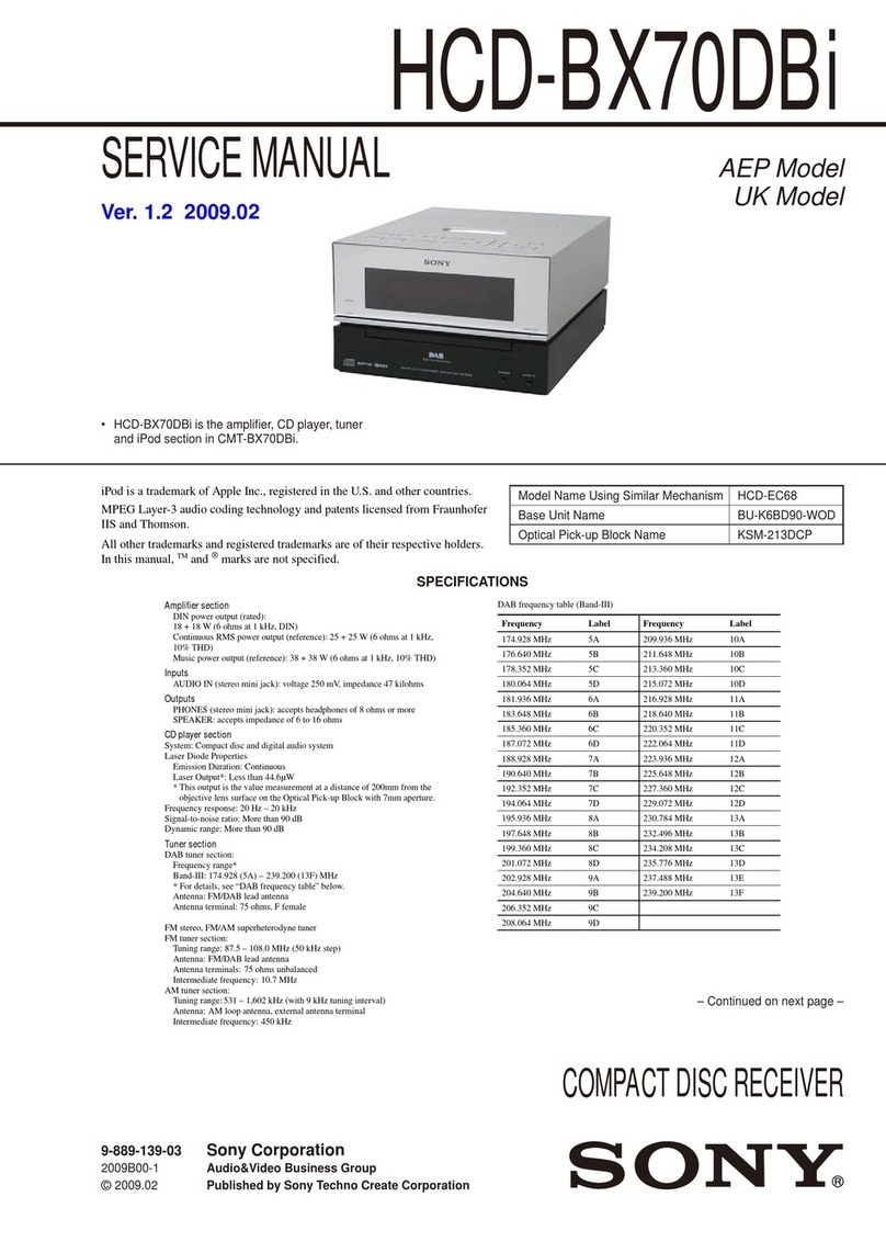
  9. Sony HCD-H170 User manual

Sony HCD-H170 User manual

Other manuals for HCD-H170

2

This manual suits for next models

2

Other Sony Receiver manuals

Sony STR-DG300 User manual

Sony

Sony STR-DG300 User manual

Sony AVD-S10 User manual

Sony

Sony AVD-S10 User manual

Sony STR-DN2010 Manual de instrucciones User manual

Sony

Sony STR-DN2010 Manual de instrucciones User manual

Sony AC-300MD User manual

Sony

Sony AC-300MD User manual
Sony STR-DG800 User manual

Sony

Sony STR-DG800 User manual

Sony PDBK-MK1 User manual

Sony

Sony PDBK-MK1 User manual

Sony MEX-N6001BD User manual

Sony

Sony MEX-N6001BD User manual

Sony DMX-NV1  (For DMX-NV1 model sold separately) User manual

Sony

Sony DMX-NV1 (For DMX-NV1 model sold separately) User manual

Sony STR-DH800 User manual

Sony

Sony STR-DH800 User manual

Sony STR-GX909ES User manual

Sony

Sony STR-GX909ES User manual

Sony HWS-AV10K User manual

Sony

Sony HWS-AV10K User manual

Sony STR-DA4600ES - 7.1 Channel Es Receiver Owner's manual

Sony

Sony STR-DA4600ES - 7.1 Channel Es Receiver Owner's manual

Sony DRN-XM01C User manual

Sony

Sony DRN-XM01C User manual

Sony ICF-SW20 User manual

Sony

Sony ICF-SW20 User manual

Sony STR-AV560 User manual

Sony

Sony STR-AV560 User manual

Sony ICF-SW1000T User manual

Sony

Sony ICF-SW1000T User manual

Sony STR-DA5000ES - Fm Stereo/fm-am Receiver User manual

Sony

Sony STR-DA5000ES - Fm Stereo/fm-am Receiver User manual

Sony HCD-DZ555K User manual

Sony

Sony HCD-DZ555K User manual

Sony HCD-HDX285 - Dvd Home Theater System User manual

Sony

Sony HCD-HDX285 - Dvd Home Theater System User manual

Sony STR-DV10 - Fm Stereo/fm-am Receiver Quick start guide

Sony

Sony STR-DV10 - Fm Stereo/fm-am Receiver Quick start guide

Sony ICF-7601 User manual

Sony

Sony ICF-7601 User manual

Sony icf 2010 User manual

Sony

Sony icf 2010 User manual

Sony BKM-126M User manual

Sony

Sony BKM-126M User manual

Sony HCD-GNZ55D User manual

Sony

Sony HCD-GNZ55D User manual

Popular Receiver manuals by other brands

Televes ZAS HD SAT user manual

Televes

Televes ZAS HD SAT user manual

Realistic DX-75 Operating and service instructions

Realistic

Realistic DX-75 Operating and service instructions

Saris 4620 Assembly instructions

Saris

Saris 4620 Assembly instructions

Mini DTR 206C PVR user manual

Mini

Mini DTR 206C PVR user manual

RF Elements TwistPort manual

RF Elements

RF Elements TwistPort manual

Denon DN-200WS user guide

Denon

Denon DN-200WS user guide

Yamaha RX-V467 owner's manual

Yamaha

Yamaha RX-V467 owner's manual

Russound SaphIR 858 instruction manual

Russound

Russound SaphIR 858 instruction manual

Quasonix RDMS Firmware update procedure

Quasonix

Quasonix RDMS Firmware update procedure

Pioneer XV-HTD1 Service manual

Pioneer

Pioneer XV-HTD1 Service manual

ATZ HDMI-V2-44HE150 manual

ATZ

ATZ HDMI-V2-44HE150 manual

Grundig STR 7122 TWIN Service manual

Grundig

Grundig STR 7122 TWIN Service manual

Creative Blaster Modem user guide

Creative

Creative Blaster Modem user guide

Panduit ATLONA AT-OME-RX11 installation guide

Panduit

Panduit ATLONA AT-OME-RX11 installation guide

VOLTCRAFT UTPS-40 operating instructions

VOLTCRAFT

VOLTCRAFT UTPS-40 operating instructions

JVC KW-ADV794 instructions

JVC

JVC KW-ADV794 instructions

Litelink VT-1001 operating instructions

Litelink

Litelink VT-1001 operating instructions

Sangean WR-11 Service manual

Sangean

Sangean WR-11 Service manual

manuals.online logo
manuals.online logoBrands
  • About & Mission
  • Contact us
  • Privacy Policy
  • Terms and Conditions

Copyright 2025 Manuals.Online. All Rights Reserved.

HCD-H170/H170K/H700
SERVICE
MANUAL
HCD-H170,
HCD-H170K
and
HCD-H700
are
the
tuner,
deck,
CD
and
amplifier
section
in
FH-B170//B177,
FH-B170K
and
MHC~-700
respectively.
AEP
Model
HCD-
H170,
UK
Model
E
Model
HCD-
170/HCD-
170K
Australian
Model
HCD-H170
Dolby
noise
reduction
manufactured
under
ticense
from
Dolby
Laboratories
Licensing
Corporation.
“DOLBY”
and
the
double-D
symbol
DQ
are
trademarks
of
Dolby
Laboratories
Licensing
Corporation.
PHOTO:
HCD-
H170K
Model
Name
Using
Similar
Mechanism
|
NEW
CD
Mechanism
Name
CDM13B-5BD4A
Base
Unit
Name
BU-5BD4A
CD
Section
DECK
Model
Name
Using
Similar
Mechanism
|
NEW
;
Tape
Transport
Mechanism
|
DECK
A
|
TCM-190RA13A
Section
Type
DECK
B
|
TCM-
190RB22A
SPECIFICATIONS
Tuner
section
FM
stereo,
FM/AM
superheterodyne
tuner
FM
tuner
section
Tuning
range
87.5
—
108
MHz
Antenna
FM
lead
antenna
Inputs
Compact
disc
player
section
(HCD-H700)
For
HCD-H170K
System
Compact
disc
digital
Telescopic
antenna
MIX
MIC.1
and
MIX
MIC
audio
system
(HCD-H170,
H170K)
2
(minijack):
Laser
Semiconductor
laser
Antenna
terminals
Sensitivity
1
mV,
(\
=
780
nm)
75
ohm
unbalanced
impedance
600
ohms
Emission
duration:
Intermediate
frequency
PHONO
(phono
jack):
Continuous
10.7
MHz
sensitivity
5
mV,
Laser
output
Max.
44.6.W*
AM
tuner
section
Tuning
range
AEP,UK
model
MW:
531
—
1,602
kHz
LW:
153
—
279
kHz
E,
Saudi
Arabia,
Australian
models
MW:
531
—
1,602
kHz
SW:
5.95
—
17.9
MHz
Antenna
AM
Ioop
antenna
External
antenna
terminals
Intermediate
frequency
.
450
kHz
Amplifier
section
Continuous
RMS
power
output
25
+
25
watts
(6
ohms
at
1
kHz,
DIN)
Peak
music
power
output
(E,
Saudi
Arabia,
Australian
model)
240
watts
(4
speakers
driven)
impedance
47
kilohms
For
HCD-H700
MIX
MIC
(minijack):
Sensitivity
1
mV,
impedance
600
ohms
PHONO
(phono
jack):
sensitivity
5
mV,
impedance
47
kilohms
For
HCD-H170
MIX
MIC
(minijack):
Sensitivity
1
mV,
impedance
600
ohms
VIDEO/AUX
(phono
jack):
sensitivity
5
mV,
impedance
47
kilohms
Outputs
HEADPHONES
(stereo
minijack):
accept
headphones
of
8
ohms
or
more.
SPEAKERS:
accept
impedance
of
6
to
16
ohms.
*
This
output
is
the
value
measured
at
distance
of
about
200
mm
from
the
objective
lens
surface
on
the
Optical
Pick-up
Block.
Signal-to
noise
ratio
More
tha
95
dB
Dynamic
range
More
than
90
dB
Cassette
deck
section
Recording
system
4-track
2-channel
stereo
Frequency
response
(DOLBY
NR
OFF)
60
—
13,000
Hz
(+3
dB),
using
TYPE
|
cassette
(Sony
HF-S)
60
—
14,000
Hz
(+3
cB),
using
TYPE
Il
cassette
Wow
and
flutter
0.1%
WRMS
+0.3%
(DIN)
—
continued
on
next
jzage
—
COMPACT
DISC
DECK
RECEIVER
SONY.
Speaker
section
Speaker
system
3
way
system
Speaker
units
Woofer:
13
cm
dia.,
cone
type
Tweeter:
5
cm
dia.,
cone
type
Super
tweeter:
2
cm
dia.,
dome
type
Enclosure
Bass
reflex
Frequency
range
60
Hz
—
20
kHz
Sensitivity
88
dB/w/im
Rated
impedance
6
ohms
Dimensions
Approx.
195
x
285
x
230
mm
(7
5/8x
11
1/4x9
inches)
Weight
Approx.
3.0
kg
(6
Ib
10
oz)
net
per
speaker
General
=
Desti-
Power
Power
nation
|_
requirements
consumption
[
AEP
220-
230V
60
watts
nee
AC,
50/60Hz
Tha
Us
sabe
ears
115
watts
[eanene!
Nad
E
100V-120V
Sa
em
or
220V-
ut
Arabia!
240V
AC
|
60
watts
Australian
.
eel
adjustable,
—
50/60Hz
Dimensions
Approx.
225
x
285
x
268
mm
(w/h/d)
(8
7/8x
11
1/4x
10
5/8
inches)
incl.
projecting
parts
and
controls
Weight
Approx.
6.2
kg
(13
Ib
11
02)
Accessories
supplied
AM
loop
antenha
(1)
Remote
commander
(1)
Sony
SUM-3
(NS)
batteries
(2)
FM
lead
antenna
(1)
(HCD-H700
only)
Speaker
cords
(2)
(HCD-H700,
except
for
the
UK
model)
Design
and
specifications
subject
to
change
without
notice.
Note
This
appliance
conforms
with
EEC
Directive
87/308/EEC
regarding
interference
suppression.
This
appliance
is
classified
as
a
CLASS
1
LASER
product.
The
CLASS
1
LASER
PRODUCT
label
is
located
on
the
rear
exterior.
CLASS
1
LASER
PRODUCT
LUOKAN
1
LASERLAITE
KLASS
t
LASERAPPARAT
TABLE
OF
CONTENTS
Section
itle
Page
1.
SERVICING
NOTES
Pee
err
a
tee
ee
ee
ee
eer
a
3
2.
GENERAL
ee
ee
ee
ee
ene
Se
eee
ee
SE
ee
ee
ee
TS
5
3.
DISASSEMBLY
3-
i.
Case
Re
Ree
ee
a
RC
RAT
Ee
Ie
ee
ee
ae
eS
25
3-2.
Power
Block
deals
see's
ilecer'Se\eie
ove.
8
8's
@c00aCe
ee
lere
ae
aye
25
3-3.
Main
Board
5
Sisie
le.
bse,
b
4
cese
vole
sew
Ae
ya
rete
O
Sueiecdc
wherese
Oars
26
3-4.
CD
Mechanism
Block
wom
e
cree
rerecessenaersvece
26
3-5.
TC
Mechanism
Block
eee
c
eee cce
eran
esncrercns
27
3-6.
Volume/MIC
HP/Display/SW
Board
-::::--:--
27
4.
MECHANICAL
ADJUSTMENTS
------s
ccc
ccc:
28
5.
ELECTRICAL
ADJUSTMENTS
«-+s:+s-csssresctees
28
6.
DIAGRAMS
6-1.
Semiconductor
Lead
Layouts--:++ersssserere
34
6-2.
Circuit
Boards
Location
:+++++ssrrsserrr
reese
35
6-3.
Printed
Wiring
Boards
—Main
Section—--:::
37
6-4.
Schematic
Diagram
—Main
Section—-----++:::
41
6-5.
Schematic
Diagram
—Sub
Section—
«-°-++'::
46
6-6.
Printed
Wiring
Boards
—Sub
Section—
:-::::
51
6-7.
Printed
Wiring
Boards
—Display
Section—:--
56
6-8.
Schematic
Diagram
—Display
Section—
---:::
59
6-9.
Schematic
Diagram
—BD
Section—--:::+-"'::
62
6-
10.
IC
Pin
Description
ee
ee
67
7.
EXPLODED
VIEWS
7-1.
Case,
Power
Section
«:srcrrtrrrteteeereeeeer
es
71
7-2.
Front
Panel,
Main
Board
Section
--+++:*+"'
+:
72
7-3.
MD
Chassis
Section-:::++erseretereseeeestei
es
73
7-4.
Mechanism
Deck
Section
(1)
-:trrerrter
ees
74
7-5.
Mechanism
Deck
Section
(2)
s+++rrtrererer
ts
75
7-6.
CD
Section
(l)errsr
rrr
eter
reece
eee
eee
cere
ee
16
7-7.
CD
Section
(2)-srrrseeeer
rere
rereeeeeee
rece
ee
77
8.
ELECTRICAL
PARTS
LIST
«++: esse
cr
eee
seer
cree
en
ee
78
SAFETY-RELATED
COMPONENT
WARNING!!
COMPONENTS
IDENTIFIED
BY
MARK
A
OR
DOTTED
LINE
WITH
MARK
A
ON.
THE
SCHEMATIC
DIAGR
AMS
AND
IN
THE
PARTS
LIST
ARE
CRITICAL
TO
SAFE
OPERATION.
REPLACE
THESE
COMPONENTS
fVITH
SONY
PARTS
WHOSE
PART
NUMBERS
APPEAH
AS
SHOWN
IN
THIS
MANUAL
OR
IN
SUPPLEMENTS
PUB-
LISHED
BY
SONY.
SECTION
1
SERVICING
NOTES
MODEL
IDENTIFICATION
—
Specification
Labels
—
HCD-H170
HCD-H170K
HCD-H700
SONY?
movet
no.
COMPACT
DISC
DECK
RECEIVER
SERIAL
NO.
MADE
IN
JAPAN
AEP
model
:
AC
:
220-230V~50/60Hz
60W
E,
Saudi
Arabia
Australian
model:
AC
:
100-120/220-240~50/60Hz
6OW
UK
model:
AC:
240V~50Hz
115W
On
operating
voltage
Battery
Installation
|
Before
operating
the
stereo
system,
check
that
the
operating
voltage
of
your
system
is
identical
with
the
voltage
of
your
local
power
supply
220-230V
AC,
50/60Hz
240V
AC,
50Hz
Saudi
Arabia
|
100V-120V//220V-
Australian
240V
AC,
adjustable,
model
50/60Hz
VOLTAGE
SELECTOR
{
10V-120V
220V-240V
Install
the
two
R6
(size
AA)
batteries
in
the
supplied
remote
commander
for
remote
control
operation.
Battery
life
About
half
a
year
of
normal
operation
can
be
expected
when
using
the
Sony
SUM-3
(NS)
batteries.
When
the
battéties
are
exhausted,
the
commander
cannot
operate
the
stereo
system.
When
this
happens,
replace
both
batteries
with
new
ones.
To
avoid
battery
leakage
if
the
commander
is
not
to
be
used
for
a
long
time,
remove
the
batteries
to
avoid
damage
caused
by
battery
leakage
and
corrosion.
LASER
DIODE
AND
FOCUS
SEARCH
OPERATION
NOTES
ON
HANDLING
THE
OPTICAL
PICK-UP
BLOCK
CHECK
OR
BASE
UNIT
1.
Make
POWER
switch
on
with
no
disc
inserted
and
disc
The
laser
diode
in
the
optical
pick-up
block
may
suffer
table
closed.
electrostatic
break-down
because
of
the
potential
difference
2.
Confirm
that
the
following
operation
is
performed
while
generated
by
the
charged
electrostatic
load,
etc.
on
clothing
observing
the
objecting
lens.
and
the
human
body.
During
repair,
pay
attention
to
electrostatic
break-down
and
also
use
the
procedure
in
the
printed
matter
which
is
included
in
the
repair
parts.
The
flexible
board
is
easily
damaged
and
should
be
handled
with
care.
NOTES
ON
LASER
DIODE
EMISSION
CHECK
The
laser
beam
on
this
model
is
concentrated
so
as
to
be
focused
on
the
disc
reflective
surface
by
the
objective
lens
in
the
optical
pick-up
block.
Therefore,
when
checking
the
laser
diode
emission,
observe
from
more
than
30
cm
away
from
the
objective
lens.
@
Confirm
that
laser
beam
is
spread.
@
Up
and
down
motion
of
the
objective
lens.
(3
times)
HOW
TO
OPEN
THE
DISC
TRAY
WHEN
POWER
SWITCH
TURNS
OFF
(1)
Insert
to
@
for
tapering
driver,
etc.,
and
turn
in
the
direction
of
arrow
OFF.
(Disc
tray
open)
(2)
Tray
as
come
out
little
of
front
panel,
pull
out
in
the
direction
of
arrow
@
by
hand.
BOTTOM
VIEW
FRONT
ON
OFF
(K
»)
(DISC
TRAY
OPEN)
‘o
—4—
:134
FH-B170/B177
MHC-700
SECTION
2
GENERAL
Parts
Ke(evaliiiversiiley
a
Refer
to
the
pages
indicated
in
parenthesis
for
use
of
the
buttons.
Tuner
Section
EY
(1)
POWER
ON/STANDBY
switch
[2]
Remote
sensor
[3]
TIMER
button
(100)
[4]
TIMER
REC
button
(104)
5}
Display
window
(6)
PRESET/TIMER
+/-
buttons
{52,
100,
104)
[7]
BAND
button
(48)
[8]
MEMORY/NEXT
button
(52,
100,
104)
[5]
STEREO/MONO
button
(50)
1]
TUNING
+/—-
buttons
(48)
Amplifier
Section
[J
{1]
MIC
(microphone)
1
and
2
LEVEL
controls
(only
for
FH-B170K)
(112)
(2]
MIX
MIC
1
and
2
jacks
(for
FH-B170K)
(142)
MIX
MIC
jack
(for
other
models)
(112)
(3)
HEADPHONES
jack
(22)
[4]
ECHO
LEVEL
control
(onty
for
FH-B170K)
(112)
[&}
MPX
(multiplex)
button
and
indicator
(only
for
FH-B170K)
(114)
(6)
VOLUME
control
(22)
[7]
PRESET
button
and
indicators
(62)
[8]
FUNCTION
button
(8)
DBFB
(Dynamic
Bass
Feed
Back)
button
and
indicator
(22)
[f0]
KARAOKE
PON
(vocal
reduction)
button
and
indicator
(for
FH-B170K)
(114)
S-SUR
(simulated
surround)
button
(for
other
models)
(22)
fi)
EQ
(equalizer
ON/OFF)
button
(62)
136
This
section
is
extracted
from
instruction
manual,
Parts
To lTal
titer)
tte)
}
Cassette
Deck
Section
1}
Cassette
holders
2)
HIGH
SPEED
button
(72)
[3}
CD
SYNC
button
(86,
94,
98)
EJECT
button
(for
deck
A)
(56)
DIRECTION
MODE
selector
(56)
Tape
operating
buttons
(for
deck
A
and
B)
b>
(fast
wind
and
AMS’)
button
(56)
‘#4
(rewind
and
AMS‘)
button
(56)
>:
Forward
play
button
and
direciton
indicator
(56)
<I:
Reverse
play
button
and
direction
indicator
(56)
@:
Stop
button
(56)
[7]
REC
@
(recording)
button
[8]
PAUSE
If
button
(56)
[9}
EJECT
A
button
(for
deck
8)
(68)
DOLBY
NR
selector
(56)
CD
Player
Section
[2)
{1)
Disc
tray
(24)
[2]
CHECK
button
(42)
[3]
EDIT/TIME
FADE
button
(78,
90)
[4]
PLAY
MODE
buttons
CONTINUE
button
(38)
SHUFFLE
button
(38)
PROGRAM
button
(40,
96)
[5]
&
OPEN/CLOSE
button
(24)
{6}
Dit
(ptay/pause)
button
(24)
(stop)
button
(24)
IkkQ¢4/b>D>1
(manual
search/AMS’)
buttons
(26,
96)
[9]
REPEAT
button
(32)
3S]
(&]
(=
"AMS
is
the
abbreviation
of
Automatic
Music
Sensor.
Parts
ofelarinicersiicela|
Remote
Commander
CLOCK
DISPLAY
button
(20)
TAPE
function
button
[3]
DECK
A/B
selector
CD
function
button
[5]
TUNER/EQ/CD
selector
[6]
CHECK
button
(42)
TUNER
function
button
VIDEO
function
button
[9]
PHONO
function
button
MEMORY
button
(66)
DBFB
button
(22)
SLEEP
button
(110)
SYSTEM
POWER
button
Tape
operating
buttons
15]
CD
player
operating
buttons
CLEAR
button
(38)
TUNER/EQ/CD
numeric
buttons
(28,
62)
CURSOR
CONTROL
buttons
(64)
VOL
+/
-
(volume
control)
buttons
(22)
EQ
button
(62)
How
to
Use
This
Manual
This
manual
applies
MHC-700
for
Europe
and
the
U.K.,
FH-8177
for
Europe,
FH-
B170
for
the
U.S.A.
and
other
countries
and
FH-B170K
for
other
countries.
The
differences
between
them
are
indicated
below:
Yes:
Equipped
No:
Not
equipped
Destina-
,
:
|
Europe “Other
tion
USA
and
UK
|countries
Receivable
FM/LW/|FM/MW/
band
AMIFM
i
mw
|
sw.
oly
PHON
[jack
°
No
Yes
No
VIDEO/
AUX
jack
Yes
No
|
Yes
Equipped
antenna
for
FM
reception
MHC-700:
FM
lead
antenna
FH-B177,
B170
and
B170K:
Telescopic
antenna
In
this
manual,
the
illustrations
of
the
unit
are
illustrated
as
FH-B177.
How
this
manual
is
composed
Please
read
the
instructions
in
this
manual
referring
to
the
illustrations.
The
letters
in
the
illustrations
correspond
to
those
in
the
text:
€@.9.
Speaker
Cord
Connection
EY
¢The
step
numbers
in
the
illustrations
correspond
to
those
in
the
text.
«Use
the
page
numbers
in
‘‘Parts
identification”
at
the
end
of
this
manual
as
an
index
to
find
out
how
to
use
the
buttons
and
controls.
a,
,
Tuner
section
45mm
°The
receivable
band
stations
differ
(5/8
in.)
depending
on
the
model
where
it
is
destinated
for.
Please
see
the
table
in
“How
to
Use
this
Manual’.
2
*
You
can
store
up
to
30
stations
(for
the
USA
model)
or
40
stations
(except
for
the
USA
modei).
Amplifier
section
*
OBFB
(Dynamic
Bass
Feedback)
system
reinforces
bass
sound.
*
You
can
easily
adjust
the
music
to
your
taste
by-selecting
from
5
factory-preset
graphic
equalizer
settings.
*You
can
store
up
to
5
individual
settings
of
graphic
equalizer.
«You
can
select
directly
the
desired
program
source
just
by
pressing
the
operation
button
(BAND,
PRESET/
TIMER
+/-,
or
TUNING
+/-
to
select
the
tuner,
Dal.
to
select
the
CO
player,
and
<I
or
D
to
select
the
cassette
deck)
on
the
program
source
equipment.
(Automatic
Source
Selection)
CD
player
section
*
You
can
enjoy
listening
in
various
playing
modes.
*
Edit
functions
allow
you
to
program
selections
automatically
to
fit
in
a
desired
duration.
Cassette
deck
section
*
Auto-reverse
decks
enable
repeated
playback
of
both
sides
of
the
cassette.
*CD
synchro
function
enables
easy
recording
of
a
CD.
*
Double
decks
enable
tape
dubbing
and
continuous
playback.
Connections
Notes
on
connection
*Connect
the
AC
power
cord
last.
«Cord
plugs
and
jacks
are
color
coded.
Red
plugs
and
jacks
are
for
the
right
channel
(R)
and
white
ones
for
the
left
channel
(L).
aker
Cord
Connecti
1
Strip
15
mm
(5/8
inches)
of
the
speaker
cord
coating
from
the
end
of
the
cord.
2
Connect
the
right
speaker
to
A,
with
the red
cord
to
+
and
the
black
cord
to
-.
Connect
the
left
speaker
to
L,
with
the
red
cord
to
+
and
the
black
cord
to
To
attach
the
speakers
to
the
main
unit
—
For
FH-B177,
8170
and
B170K
only
E}
1.
Unlock
the
stopper
and
slide
the
speaker
so
that
it
hooks
to
the
system.
2
Lock
the
stopper.
AM
Loop
Antenna
Connection
@
For
the
European
and
U.K.
model
C-1
For
the
models
for
other
countries
Connect
the
supplied
loop
antenna
to
the
AM
and
7
terminals,
FM
Lead
Antenna
Connection
(MHC-700
onty)
2)
Connect
the
supplied
FM
lead
antenna
to
the
FM
752
terminal
and
extend
horizontally.
iy
eis
ing!
16
Rehan
Connections
For
Better
FM
Reception
&
3
For
the
European
and
U.K.
model
1E-1
Connect
the
outdoor
FM
antenna
to
the
FM
75
2
terminal,
using
75-ohm
coaxial
cable
and
!EC
standard
socket
connector.
-
For
the
models
for
other
countries
ea
Connect
the
outdoor
FM
antenna
to
the
j
FM
752
and
+h
terminals,
using
75-ohm
=
coaxial
cable.
For
Better
AM
Reception
For
the
European
and
U.K.
model
For
the
models
for
other
countries
ewe
Use
the
6-
to
15-meter
(20-
to
50-feet)
insulated
wire
for
connecting
the
terminal.
Connect
the
+
terminal
to
a
good
ground.
When
you
use
an
external
antenna,
be
sure
to
ground
it
against
lightening.
Never
connect
the
ground
wire
to
a
gas
pipe.
Doing
so
is
extremely
dangerous.
ER
RE
AE
NRRL
EE
Power
Connection
Connect
the
supplied
AC
power
cord
to
AC
IN
and
the
other
end
to
a
wail
outlet.
RK-C74
To
attach
the
AM
loop
antenna
to
the
main
unit
in
order
to
carry
the
unit
3
See
the
illustration.
[e¥
VIDEO/AUX
D>
Ot
Or
LINE
OUT
18
Adding
Other
Components
to
the
System
EY
Turntable
system
DS]
(For
the
European
and
U.K.
model)
You
can
connect
a
turntable
system
to
the
PHONO
jacks.
To
listen
to
the
turntable
system,
press
FUNCTION
on
the
front
panel
until
“PHONO”
appears
‘on
the
display.
VTR
Ey
(For
the
model
for
other
countries)
You
can
connect
a
VTR,
etc.
to
the
VIDEO/AUX
jacks.
To
listen
to
the
connected
equipment,
press
FUNCTION
on
the
front
panel
until
“VIDEO/AUX”’
appears
on
the
display.
Changing
the
MW
tuning
interval
(except
for
the
European
and
U.K.
mode!)
The
MW
tuning
interval
is
preset
at
the
factory
to
10
kHz
for
the
USA
model,
and
9
kHz
for
the
models
for
other
countries.
if
you
use
the
system
where
the
frequency
allocation
system
is
different
from
the
preset
interval,
change
the
interval
as
follows:
1
Turn
on
the
power.
2
Tune
in
any
MW
station.
3
Turn
off
the
power.
4
Turn
the
power
back
on
while
pressing
the
TUNING
+
button.
To
reset
the
interval,
follow
the
same
procedure.
Important
When
the
interval
is
changed,
stored
stations
will
be
erased
from
the
memory.
1
TIMER:
TIMER
REC
MEMORY/NEXT
MEMORY/NEXT
~
*
Clock
Setting
Setting
the
Clock
Example:
Set
to
9:25
in
the
morning.
1
Press
TIMER
and
TIMER
REC
at
the
same
time,
2
Set
the
hour
with
PRESET/TIMER
-
or
+
button.
3
Press
MEMORY
/NEXT.
4
Set
the
minute
with
PRESET
/TIMER
-
oF
+
button,
5
Press
MEMORY/NEXT.
The
clock
starts
operating.
Information
on
the
time
The
European
and
U.K.
model
shows
the
time
in
24-hour
cycle.
The
model
for
other
countries.
shows
the
time
In
12-hour
cycie.
AM
12:00
=
midnight
PM
12:00
=
noon
When
a
power
interruption
occurs
The
clock
and
timer
settings
are
all
erased,
and
“0:00""
(‘"AM
12:00")
will
flash
on
the
display.
To
change
the
frequency
display
to
the
time
display
Press
CLOCK
DISPLAY
on
the
remote
commander.
The
time
is
displayed
for
about
4
seconds,
then
the
time
display
changes
into
the
frequency
display.
OBFB
$-SUA
a
Audio
Adjustment
Volume
Adjustment
£¥
Turn
VOLUME
clockwise
to
increase
the
sound
level,
or
counterclockwise
to
decrease
it.
(Or
press
VOL
+
or
—
on
the
remote
commander.)
Sound
Quality
Adjustment
To
reinforce
bass
EJ
Press
DBFB*.
To
activate
surround
effect
for
stereo
sound
[9
(Except
for
FH-B170K)
Press
S-SUR**
during
a
stereo
sound
reproduction.
This
creates
the
atmosphere
of
a
movie
theater
or
concert
hall.
This
function
is
not
effective
for
a
monaural
sound.
(For
FH-B170K)
The
KARAOKE
PON
button
is
provided
here,
See
page
114.
For
personal
listening
2)
Connect
headphones
to
HEADPHONES.
No
sound
comes
from
the
speakers.
“DBFB
=
Dynamic
Bass
Feedback
**§-SUR
=
Simulated
surround
Eo
OFF
SOE
LAE
EB
aR
Rete
24
CD
Playing
Playing
the
En
Cc
1
Press
&
OPEN/CLOSE
to
open
the
tray.
Place
a
disc
with
the
printed
side
up.
2
Press
Di.
(>
on
the
remote
commander)
The
tray
closes
and
play
starts.
The
display
shows
Ff]
the
current
track
number,
[J
the
current
INDEX
number
(of
the
track),
(§
elapsed
playing
time
of
the
track
and
i}
track
numbers.
Caution
on
adjusting
volume
Do
not
turn
up
the
volume
while
listening
to
a
portion
with
very
low
level
inputs
or
no
audio
signals.
If
you
do,
the
speakers
may
be
damaged
when
a
peak
level
portion
is
played.
To
stop
play
Press
Ml.
To
stop
for
a
moment
during
play
Press
Dit
(tf
on
the
remote
commander).
To
resume
play,
press
it
again.
To
stop
play
and
open
the
tray
Press
&
OPEN/CLOSE.
To
play
an
8
cm
(3-inch)
CD
Piace
it
on
the
inner
circle
of
the
tray.
if
the
disc
is
provided
with
an
adaptor,
first
remove
it.
Do
not
put
a
normal
CD
(12
cm/5-inch)
on
top
of
an
8cm
CD.
CD
Playing
Locating
a
Particular
Selection
—
Automatic
Music
Sensor
(AMS)
The
AMS
locates
the
beginning
of
a
selection.
To
locate
the
beginning
of
the
current
or
preceding
selection
LY
Press
[Kkiéd(or
I44
on
the
remote
commander)
as
many
times
as
required.
To
locate
the
beginning
of
a
succeeding
setection
[EE]
Press
>PD>{
(or
PPI
on
the
remote
commander)
as
many
times
as
required.
Locating
a
Particular
Point
i
a
Selection
You
can
locate
any
particular
point
in
the
selection.
This
function
works
during
play
or
pause.
This
operation
is
impossible
with
the
remote
commander.
To
search
while
monitoring
the
sound
To
move
forward
at
high
speed
E}
Keep
PDD]
depressed
and
release
it
at
the
desired
point.
To
move
backward
at
high
speed
[J
Keep
Ikk#44
depressed
and
release
it
at
the
desired
point.
To
search
quickly
1
Press
Dil
to
set
the
unit
in
pause
mode.
2
Keep
Ixki¢4
or
PDD]
depressed.
The
search
speed
increases,
but
there
is
no
sound.
Find
the
desired
paint
by
observing
the
display.
Press
DIE
again
at
the
desired
point
to
play.
28
CD
Playing
To
locate
a
selection
directly
Possible
only
with
the
remote
commander
1.
Set
the
TUNER/EQ/CD
selector
to
co.
2
Press
the
numeric
button
for
the
selection.
If
the
selection
number
Is
greater
than
12
Use
the
>12
and
1
to
10
buttons.
"10°"
functions
as
the
figure
‘'0."”
e.g.
To
play
from
selection
number
22,
press
>
12,
2,
2.
To
play
from
selection
number
30,
press
>
12,
3,
10.
30
CD
Playing
Information
display
Possible
only
with
the
remote
commander.
To
change
the
time
display
EY
Press
TIME
during
play.
The
display
changes
to
give
you
the
following
information.
El
Elapsed
piaying
time
of
the
current
selection
(5
Remaining
time
in
a
selection.
If
the
current
selection
number
is
over
20,
“..m--s"
is
displayed.
Remaining
time
of
the
disc.
To
display
the
total
playing
time
of
the
disc
Press
TIME
during
stop.
The
following
appears
for
about
4
seconds.
EB)
Total
number
of
selections
Total
playing
time
of
the
disc
Track
numbers
This
information
appears
also
when
you
close
the
tray
by
pressing
&
OPEN/CLOSE.
Notes
on
handling
discs
*To
keep
the
disc
clean,
handle
the
disc
by
its
edge.
Do
not
touch
the
surface.
Ej
*Do
not
stick
paper
or
tape
onto
the
disc.
1D
|
*Do
not
expose
the
disc
to
direct
sunlight
or
heat
sources
such
as
a
hot
air
duct,
nor
leave
it
in
a
car
parked
in
direct
sunlight
as
there
can
be
a
considerabie
rise
in
the
temperature.
«After
playing,
store
the
disc
in
its
case.
REPEAT
F
32
CD
Playing
Playing
Repeatedly
—
Repeat
Play
To
repeat
all
the
selections
LY
Press
REPEAT
once
during
play
so
that
“REPEAT”
appears
in
the
display.
To
repeat
a
single
selection
E}
Press
REPEAT
twice while
playing
the
desired
selection
so
that
“REPEAT
1”
—SS
appears
in
the
display.
(Operable
only
in
normal
play
and
delete
play
mode)
To
cancel
repeat
play
Press
REPEAT
so
that
neither
“REPEAT”
nor
‘REPEAT
1"
appears.
Note
Repeat
play
function
works
also
during;
«shuffle
play
«delete
play
delete
shuffle
play
*
program
play.
Multi-disc
program
play
(see
page
44)
cannot
be
repeated.