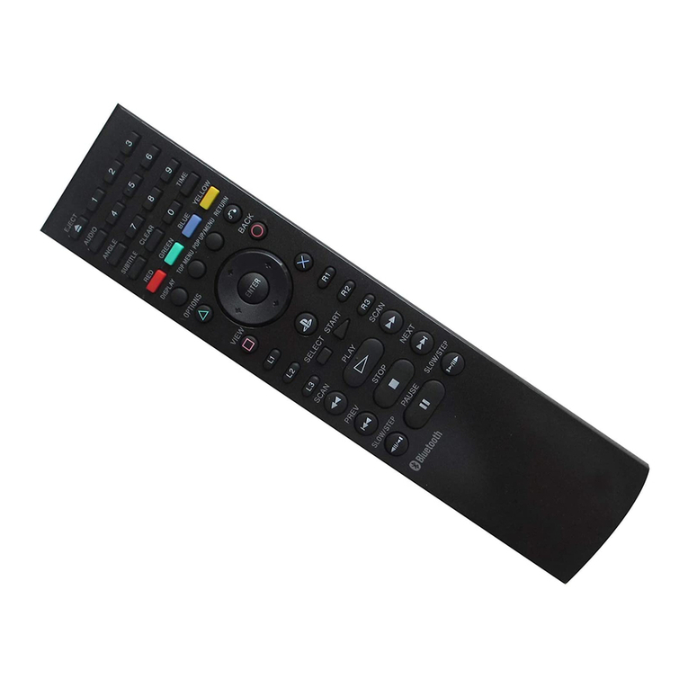
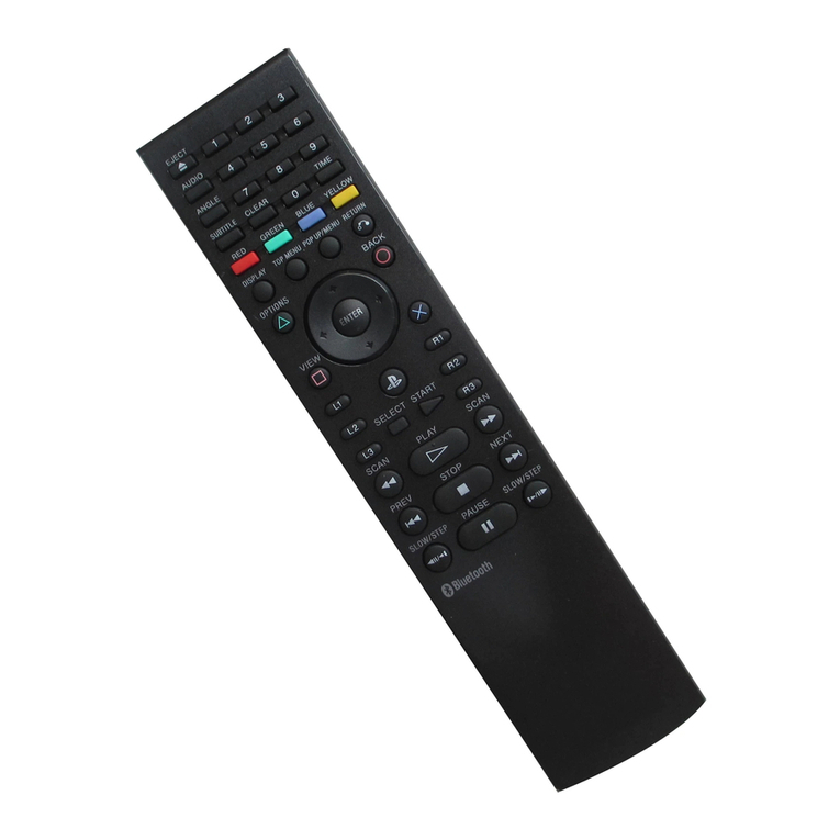
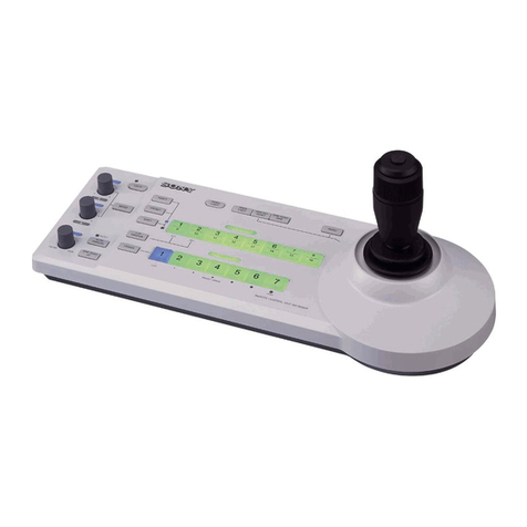
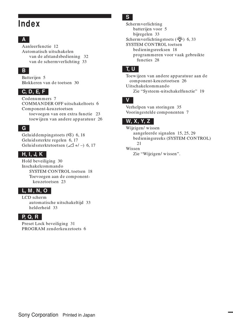
Sony RM-LF204 User manual

SONY.
7-953-14(1)
Remote
Commander
Operating
Instructions
RM-LF204
RM-LP204M
)
2000
by
Sony
Corporation

2

CE
Declaration
of
Conformity
Acer
Computer
(Shanghai)
Limited
Contact
person:
Mr.
Easy
Lai
Tel:
886-2-8691-3089,
Fax:
886-2-8691-3120
Email:
C€®
Model
number:
MS2235
Machine
type:
Aspire
5730Z/5330
SKU
number:
Aspire
5730Z/5330-xxxxx
("x"
=
0-9,
a
-
z,
or
A
-
Z)
Is
compliant
with
the
essential
requirements
and
other
relevant
provisions
of
the
following
EC
directives,
and
that
all
the
necessary
steps
have
been
taken
and
are
in
force
to
assure
EMC
Directive
2004/108/EC
as
attested
by
conformity
with
the
following
harmonized
standards:
-.EN55022:1998
+
A1:2000
+
A2:2003,
AS/NZS
CISPR22:2002,
Class
B
-EN55024:1998
+
A1:2001
+
A2:2003
-EN55013:2001
+
A1:2003
+
A2:2006
(For
AV
products)
-EN55020:2007
(For
AV
products)
-.EN61000-3-2:2006,
Class
D
-.EN61000-3-3:1995
+
A1:2001
+
A2:2005
Low
Voltage
Directive
2006/95/EC
as
attested
by
conformity
with
the
following
harmonized
standard:
-EN60950-1:2001
+A11:2004
-EN60065:2002
(For
AV
products)
Council
Decision
98/482/EC
(CTR21)
for
pan-European
single
terminal
connection
to
the
Public
Switched
Telephone
Network
(PSTN).
RoHS
Directive
2002/95/EC
on
the
Restriction
of
the
Use
of
certain
Hazardous
Substances
in
Electrical
and
Electronic
Equipment.
R&TTE
Directive
1999/5/EC
as
attested
by
conformity
with
the
following
harmonized
-EN300
328
VI.7.1

Important
safety
information
•
When
removing
from
the
socket,
never
pull
the
mains
plug
by
the
cable,
instead
take
a
hold
of
the
plug.
•
The
height
adjustable
screw
feet
must
never
be
removed.
•
The
plug
must
be
accessible
after
installing
the
machine
•
Manifold
plugs,
couplings
and
extension
cables
must
not
be
used.
Risk
of
fire
from
over¬
heating!
•
Do
not
spray
down
the
appliance
with
jets
of
water.
Risk
of
electric
shock!
•
Do
not
lean
on
the
open
door.
The
appliance
may
tip
over.
•
Once
the
drying
cycle
or
ProSteam
programme
has
been
interrupted,
the
laundry
and
drum
may
be
hot.
Risk
of
burns!
Take
care
when
removing
the
laundry.
•
Take
care
when
interrupting
the
ProSteam
programme:
Do
not
open
the
machine
door
during
the
steam
phase.
Hot
steam
may
result
in
burns.
The
display
shows
a
message
to
indicate
the
steam
phase.
•
The
final
part
of
a
drying
cycle
occurs
without
heat
(cool
down
cycle)
to
ensure
that
the
items
are
left
at
a
temperature
that
ensures
that
the
items
will
not
be
damaged.
•
A
Caution
-
Hot
surface:
Do
not
touch
the
back
of
the
appliance
while
it
is
operating.
A
WARNING!
Never
stop
a
tumble
dry
before
the
end
of
the
drying
cycle
unless
all
items
are
quickly
removed
and
spread
out
so
that
the
heat
is
dissipated.
Risk
of
fire!
•
Risk
of
electric
shock!
Do
not
spray
down
the
appliance
with
jets
of
water.
Installation
•
Note
the
"Installation"
instructions.
•
Important!
Appliance
must
be
moved
in
vertical
position
for
transport.
•
This
appliance
is
heavy.
Care
should
be
taken
when
moving
it.
•
When
unpacking
the
appliance,
check
that
it
is
not
damaged.
If
in
doubt,
do
not
use
it
and
contact
the
Service
Centre.
•
All
packing
must
be
removed
before
use..Serious
damage
can
occur
to
the
product
and
to
property
if
this
is
not
adhered
to.
See
relevant
section
in
the
user
manual.
•
Any
electrical
work
required
to
install
this
appliance
should
be
carried
out
by
a
qualified
electrician
or
competent
person.
•
Care
must
be
taken
to
ensure
that
the
appliance
does
not
stand
on
the
electrical
supply
cable.
•
If
the
machine
is
situated
on
a
carpeted
floor,
please
adjust
the
feet
in
order
to
allow
air
to
circulate
freely
under
the
appliance.
•
After
having
installed
the
appliance,
check
that
it
is
not
pressing
or
standing
on
its
electrical
supply
cable.
•
If
the
tumble
dryer
is
placed
on
top
of
a
washing
machine,
it
is
compulsory
to
use
the
stacking
kit
(optional
accessory).
Use
•
The
appliance
is
intended
for
drying
and
steam
treatment
of
standard
laundry
in
do¬
mestic
applications.
•
This
appliance
is
designed
for
domestic
use.
It
must
not
be
used
for
purposes
other
than
those
for
which
it
was
designed.
•
Only
wash
fabrics
which
are
designed
to
be
machine
dried.
Follow
the
instructions
on
each
garment
label.

GETTING
TO
KNOW
YOUR
APPLIANCE
THE
CONTROL
PANEL
O
On/Off
Switch
Second
Oven
and
Main
Oven
Cavity
Selector
Function
Selector
Speedcook
Time/Temperature
Decrease
Selector
Time/Temperature
Increase
Selector
Timer
Selector
Control
Timer
Indicators
Operating
Time
Keep
Warm
Indicator
Temperature/Time
Light/Defrost
Indicators
Cavity
Indicator
0ven
Light
i
Dual
a
x
A
A
f
—
m
Ventitherm
®
Precision
Fan
Cooking
Hot
Air
Fan
Baking
Conventional
Cooking
Rotitherm
Roasting
Fan
Controlled
Defrosting
Keep
Warm

Chapter
4:
Service
Information
Theory
of
Operation.
25
Z-80A
System
Operation.
26
Select
Code
Recognition.
26
Interrupt
System.
27
Interface
Reset.
27
Shared
Memory
Controller.
28
Addressing.
28
Read/Write
Control.
28
Clock
Circuits.
28
Memory
Access
Select
Timing.
29
Memory
Cycle
Timing.
29
Hardware
Registers.
31
Shared
RAM.
32
Default
Switches.
33
Baud
Rate
Multiplexer.
33
Line
Drivers
and
Receivers.
33
Replacement
Parts.
34

Industry
Canada
statement:
This
device
complies
with
RSS-210
of
the
Industry
Canada
Rules.
Operation
is
subject
to
the
following
two
conditions:
(1)
This
device
may
not
cause
harmful
interference,
and
(2)
this
device
must
accept
any
interference
received,
including
interference
that
may
cause
undesired
operation.
Ce
dispositif
est
conforme
a
la
norme
CNR-210
d'lndustrie
Canada
applicable
aux
appareils
radio
exempts
de
licence.
Son
fonctionnement
est
sujet
aux
deux
conditions
suivantes:
(1)
le
dispositif
ne
doit
pas
produire
de
brouillage
prejudiciable,
et
(2)
ce
dispositif
doit
accepter
tout
brouillage
regu,
y
compris
un
brouillage
susceptible
de
provoquer
un
fonctionnement
indesirable.
Caution:
(i)
the
device
for
operation
in
the
band
5150-5250
MHz
is
only
for
indoor
use
to
reduce
the
potential
for
harmful
interference
to
co-channel
mobile
satellite
systems;
(ii)
high-power
radars
are
allocated
as
primary
users
(i.e.
priority
users)
of
the
bands
5250-5350
MHz
and
5650-5850
MHz
and
that
these
radars
could
cause
interference
and/or
damage
to
LE-LAN
devices.
Avertissement
(i)
les
dispositifs
fonctionnant
dans
la
bande
5
150-5
250
MHz
sont
reserves
uniquement
pour
une
utilisation
a
I’interieur
afin
de
reduire
les
risques
de
brouillage
prejudiciable
aux
systemes
de
satellites
mobiles
utilisant
les
memes
canaux;
(ii)
De
plus,
les
utilisateurs
devraient
aussi
etre
avises
que
les
utilisateurs
de
radars
de
haute
puissance
sont
designes
utilisateurs
principaux
(c.-a-d.,
qu'ils
ont
la
priorite)
pour
les
bandes
5
250-5
350
MHz
et
5
650-5
850
MHz
et
que
ces
radars
pourraient
causer
du
brouillage
et/ou
des
dommages
aux
dispositifs
LAN-EL.
Radiation
Exposure
Statement
m
distance
20
cm
between
the
radiator
&
your
Declaration
d'exposition
aux
radiations:
Cet
equipement
est
conforme
aux
limites
d'exposition
aux
rayonnements
1C
etablies
pour
un
environnement
non
controle.
Cet
equipement
doit
etre
installe
et
utilise
avec
un
minimum
de
20
cm
de
distance
entre
la
source
de
rayonnement
et
votre
corps.

SAFETY
INSTRUCTIONS

1
Battery
bay
0
Houses
the
computer's
battery
pack.
2
Battery
release
latch
Releases
the
battery
for
removal.
3
g
Hard
disk
bay
Houses
the
computer's
hard
disk
(secured
with
screws).
4
^
Memory
compartment
Houses
the
computer's
main
memory.
5
Battery
lock
a
Locks
the
battery
in
position.
6
Ventilation
slots
and
cooling
fan
Enable
the
computer
to
stay
cool,
even
after
prolonged
use.
Note:
Do
not
cover
or
obstruct
the
opening
of
the
fan.

5
MOUNTING
-
■
Mounting
MY-CU
and
MYH-CU
To
mount
the
MY(H)-CU
monitor,
separate
the
terminals-
mounted
chassis
from
front
case.
1.
Loosen
a
screw
on
top
of
front
case.
Press
on
bottom,
right
hand,
and
the
front
case
slightly
moves
up.
2.
Then,
press
on
center
of
left
side,
which
unlocks
from
3.
Lift
gently
front
case,
then
it
separates.
4.
Disconnect
video-monitor.
Pull
off
the
holder
and
set
monitor
aside.
5.
Attach
chassis
to
wall
at
4
points.
6.
Make
wire
terminations
directly
on
6
screw
terminals.
7.
On
MY-CU
only,
wire
with
jumpers
on
audio
terminals
D1,
D2&E.
8.
Pin
the
holder,
reconnect
and
mount
front
case,
justly
aligning
to
lock.
★
Do
not
connect
any
wires
at
any
other
point
than
on
terminals.
I
Mounting
with
intercom
For
IE-1GD(U),
IE-2AD(U)
or
TD-H/A
or
B
Attacr
template:
For
IE-8MD
and
IE-8HD
Before
actually
mounting
the
unit,
attach
the
supplied
template
to
wall.
For
MY-CU/IE-8MD
combination,
attach
two
chassis
to
wall.
First,
mount
the
intercom
chassis
(or
bracket)
to
wall
or
single¬
gang
box,
and
MY-monitor
chassis
can
adjustably
be
mounted
to
its
right
side.
l|?
”
•
For
MYH-CU
and
LEF-5,10,10S
Mount
MYH-CU
to
the
left
of
LEF-5,
10,10S
intercom,
keeping
a
space
of
3
-
5
cm
(1-1/4"
~
2”)
for
brightness/
contrast
adjustment.
-10-

Warranty
The
object
area
of
X
is
the
EU.
El
area
del
objeto
X
es
la
EU.
Het
toepassingsgebied
van
X
is
de
EU.

Otherwise,
click
Next.
Files
are
auto¬
matically
copied,
then
the
Setup
Complete
screen
appears.
12.
Remove
the
Mouse
Suite
software
CD
from
the
driver.
Finish
to
activate
the
mouse
settings.

YAHTZEE
BLOCK
DIAGRAM

513
Reserved
514
Echo,
response,
dialing,
originate/answer
515
Reserved
516
Modemtestoptions
517
Reserved
518
Modem
test
timer
519
Reserved
520
Reserved
521
Auto
retrain,
RTS/CTS,
DTR,
DCD,
DSR
522
Speaker
and
response
523
RDL,
DTE
data
rate,
parity,and
guard
tone
524
Reserved
525
DTR
delay
526
RTS/CTS
delay
interval
527
Async
operation.
Line
type
536
Negotiation
Fallback
537
Maximum
line
speed
538
Forced
hangup
delay
S46
Selectdatacompression
548
Feature
negotiation
549
Bufferlowerhmit
550
Buffer
upper
limit
S63
Leased
Line
carrier
level
S82
Break
Signaling
S86
Connection
failure
code
0,
t
Bit-mapped
Bit-mapped
0-100/seconds
0-255/0.01
second
Bit-mapped
0-7
0-11
0-255
136,
138
0,
7,
128
0-255
0-255
0-15
3,
7,
128
,9,10,12-14
S98
Speakerphone
squelch
timer
0-255/.001second
10
Section
Five
-
Result
Codes
BASIC
RESPONSE
CODES
OK
0
CONNECT
1
RING
2
NO
CARRIER
3
ERROR
4
CONNECT
1200
5
NODIALTONE
6
BUSY
7
NOANSWER
8
CONNECT
2400
10
CONNECT
4800
11
CONNECT
7200
24
CONNECT
9600
12
CONNECT
12000
25
CONNECT
14400
13
CONNECT
19200
14
CONNECT
38400
28
CONNECT
57600
29
CONNECT
1200/75
22
CONNECT
75/1200
23
EXTENDED
RESPONSE
CODES
13

Loading
cutlery
by
the
water,
you
should:
ns
of
cutlery
in
the
cutlery
basket
can
be
reached
le
cut-
2.Place
forks
and
spoons
in
the
cutlery
basket's
grid
insert
wi
their
handles
pointing
down-
The
cutlery
basket
can
be
opened
Always
make
sure
that
you
put
your
hand
around
both
parts
of
the
two-
part
handle
when
removing
it
from
the
dishwasher.
.
Place
the
cutlery
basket
on
a
table
or
work
surface.
.Open
out
the
two-part
handle.
.
Remove
cutlery.
15
This manual suits for next models
1
Table of contents
Other Sony Remote Control manuals

Sony
Sony RM-DC2 User manual

Sony
Sony RM-VL710 User manual

Sony
Sony S-AIR AIR-RM10 User manual

Sony
Sony RMT-P1BT User manual

Sony
Sony RM-V8A User manual

Sony
Sony RM-VZ220 User manual

Sony
Sony Remote Commander RM-V18A User manual

Sony
Sony RMF-YD001 User manual

Sony
Sony RM-LJ301 User manual

Sony
Sony RM-PP412 User manual

Sony
Sony RM-EZ4 User manual

Sony
Sony BRH10 User manual

Sony
Sony RMF-YD001 User manual

Sony
Sony RM-VL700T Administrator guide

Sony
Sony RM-VL700 User manual

Sony
Sony PlayStation CFI-ZMR1 User manual

Sony
Sony RM-X55M User manual

Sony
Sony RMT-DSLR2 User manual

Sony
Sony CECH-ZRC1U User manual

Sony
Sony RM-V302 User manual