Sony SJ700A Series User manual

SJ700A-015~160
Scale Unit / Maßstabseinheit / 直线标尺器
Instruction Manual / Bedienungsanleitung / 使用说明书
SJ700A Series
Read all instructions in the manual carefully before use and strictly follow them.
Keep the manual for future references.
Lesen Sie die ganze Anleitung vor dem Betrieb aufmerksam durch und folgen Sie beim Betrieb des Geräts den
Anweisungen. Bewahren Sie diese Bedienungsanleitung zum späteren Nachlesen griffbereit auf.
感谢您惠购本产品。
使用之前请务必认真阅读本手册,并且严格按照手册中的规定操作。将此手册留作以后的参考。
MAGNESCALE®/

[For U.S.A. and Canada]
THIS CLASS A DIGITAL DEVICE COMPLIES WITH
PART15 OF THE FCC RULES AND THE CANADIAN
ICES-003. OPERATION IS SUBJECT TO THE
FOLLOWING TWO CONDITIONS.
(1) THIS DEVICE MAY NOT CAUSE HARMFUL
INTERFERENCE, AND
(2) THIS DEVICE MUST ACCEPT ANY
INTERFERENCE RECEIVED, INCLUDING
INTERFERENCE THAT MAY CAUSE
UNDERSIGNED OPERATION.
CET APPAREIL NUMÉRIQUE DE LA CLASSE A
EST CONFORME ÀLA NORME NMB-003 DU
CANADA.

(E) I
SJ700A
English
Symbols requiring attention
Symbols prohibiting actions
Symbols specifying actions
Safety Precautions
Sony Manufacturing Systems Corporation products are designed in full consideration of safety.
However, improper handling during operation or installation is dangerous and may lead to fire,
electric shock or other accidents resulting in serious injury or death. In addition, these actions may
also worsen machine performance.
Therefore, be sure to observe the following safety precautions in order to prevent these types of
accidents, and to read these “Safety Precautions” before operating, installing, maintaining,
inspecting, repairing or otherwise working on this unit.
Warning indication meanings
The following indications are used throughout this manual, and their
contents should be understood before reading the text.
Warning
Failure to observe these precautions may lead to fire, electric shock
or other accidents resulting in serious injury or death.
Caution
Failure to observe these precautions may lead to electric shock or
other accidents resulting in injury or damage to surrounding objects.
Note
This indicates precautions which should be observed to ensure
proper handling of the equipment.
DO NOT
DISASSEMBLE
UNPLUGGING
CAUTION ELECTRICAL
SHOCK

II (E)
SJ700A
English
Warning
•Do not use this unit with voltages other than the specified supply voltage as this may result
in fire or electric shock.
•Do not perform installation work with wet hands as this may result in electric shock.
•Do not disassemble or modify the unit as this may result in injury or damage the internal
circuits.
•Be sure to check the machine and device conditions to ensure work safety before working
on the machine.
•Be sure to cut off the power supply, air and other sources of drive power before working on
the machine. Failure to do so may result in fire or accidents.
•When turning on the power supply, etc. to operate the machine, take care not to catch your
fingers in peripheral machines and devices.
Caution

(E) III
SJ700A
English
Handling Precautions
Installation precautions
When installing this unit, care should be given to the following points to prevent noise and
electromagnetic wave interference from other equipment.
1. Do not pass lead and connection cables through the same ducts as power lines.
2. Be sure to install the unit at least 0.5 m (20") or more away from high voltage or large
current sources or high-power relays.
3. Absolutely do not bring the unit near magnets or sources of electromagnetic waves.
Note
•Magnet chucks and other sources of magnetic force of approx. 600×10–4T (600 G)
should be kept at least 50 mm (2") or more away from the side surfaces and 100 mm (4")
or more away from the opening surfaces of the scale's steel chassis.
•If the unit must be installed close to sources of magnetic force, be sure to implement
adequate electromagnetic shielding countermeasures.
Installation place precautions
1. Mount the scale for more precise positioning as closely as possible to the workpiece or to
the object being measured.
(The farther the scale is mounted from workpiece, the greater the mechanical errors grow.)
2. The scale unit should be used within an ambient temperature range of 0 to 40°C. Avoid
locations where the scale is exposed to direct sunlight and heat sources such as motors.
3. Do not place anything on the mounted scale, or step on it: excessive force to the scale
causes trouble.
4. Never install the scale in locations such as places where the scale could be exposed
directly to coolant liquid or to coolant in mist form.

IV (E)
SJ700A
English
LGeneral precautions
When using Sony Manufacturing Systems Corporation products,
observe the following general precautions along with those given
specifically in this manual to ensure proper use of the products.
•Before and during operations, be sure to check that our products
function properly.
•Provide adequate safety measures to prevent damage in case
our products should develop a malfunction.
•Use outside indicated specifications or purposes and
modification of our products will void any warranty of the
functions and performance as specified for our products.
•When using our products in combination with other equipment,
the functions and performance as noted in this manual may not
be attained, depending upon the operating environmental
conditions. Make a thorough study of the compatibility in
advance.

(E) i
SJ700A
English
Contents
1. Outline ........................................................................ 1
1-1. Introduction .......................................................... 1
1-2. Major Features ..................................................... 1
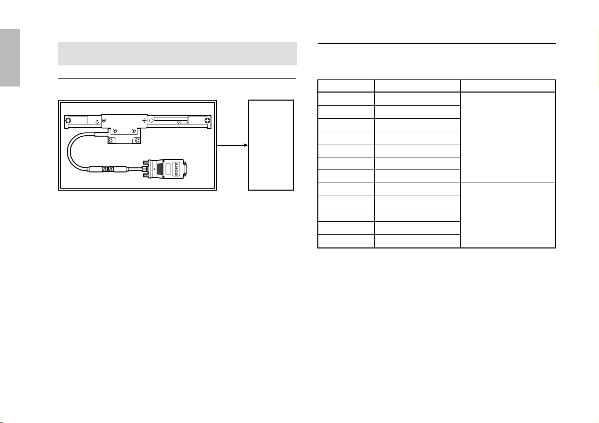
1-3. Parts Configuration .............................................. 1
1-4. System Configuration........................................... 2
2. Name and Function of Each Part ............................. 3
3. Mounting Method ....................................................... 5
3-1. Mounting Precautions .......................................... 5
3-1-1. Checking the mounting method ................ 5
3-1-2. Setting the operating range ...................... 6
3-1-3. Protection of the head cable .................... 6
3-1-4. Mounting a protective cover ..................... 6
3-2. Required Items for Mounting ................................ 7
3-3. Mounting Procedure............................................. 8
3-4. Mounting Dimensions .......................................... 8
3-4-1. Mounting of scale ..................................... 9
3-4-2. Mounting of the slider ............................. 11
3-4-3. Removal of the slider holder ................... 14
3-4-4. Checking of the operating range ............ 15
3-4-5. Mounting of the conduit cable ................. 15
3-4-6. Connection of the head cable to
a counter unit .......................................... 16
3-4-7. Removal of the scale .............................. 17
4. Specifications .......................................................... 18
4-1. General Specifications ....................................... 18
4-2. Dimensions ........................................................ 19
5. Trouble Information ................................................. 20

ii (E)
SJ700A
English

English
(E) 1
SJ700A
1-1. Introduction
SJ700A series of linear scales are semi-modular types that
incorporate the detector inside the scale, and the relative
positions of their scale and head are adjusted and secured using a
slider holder.
The SJ700A series may be used as is by connecting it to a Sony
Manufacturing Systems Corporation counter unit (LG20, LH70
series).
1-2. Major Features
•Compact size and light weight
•Easy to install
•Same coefficient of expansion as that of machine tools
•Highly resistant to oils and dirt
1. Outline
1-3. Parts Configuration
Scale unit Scale .......................................................... 1
Accessories
Cable clamps ................................... 4
(For securing the conduit cable)
+P 4 x10 ........................................ 4
(For securing wires)
Spacers ............................................ 5
(For securing the slider)
HSB M4 x10 ................................... 3
(For securing the scale)
Screening label ................................ 1
(For covering the screw holes when
the slider holder is removed)
HSB M4 x14 ................................... 2
(For securing the slider)
Plain washers (S) ............................ 2
(For securing the slider)
HSB M5 x25 ................................... 2
(For securing the slider)
Plain washers (M) ............................ 3
(For securing the scale)
Nuts (for M5) .................................... 2
(For securing the slider)
Instruction manual .................................................................... 1

English
2(E)
SJ700A
Model line up
Unit: mm (inch)
Scale unit Counter
(optional)
LG20
LH70
Series
Model name Measuring length Cable length
SJ700A-015 150 (5.91")
SJ700A-025 250 (9.84")
SJ700A-035 350 (13.78")
SJ700A-040 400 (15.75") 3000 (118.11")
SJ700A-050 500 (19.69")
SJ700A-065 650 (25.59")
SJ700A-080 800 (31.50")
SJ700A-095 950 (37.40")
SJ700A-105 1050 (41.34")
SJ700A-125 1250 (49.21") 5000 (196.85")
SJ700A-140 1400 (55.12")
SJ700A-160 1600 (62.99")
1-4. System Configuration
System configuration

English
(E) 3
SJ700A
2. Name and Function of Each Part
SerialNo.
SJ700A-***
******
Magnescale
COMBINATIONNo.
*****
Alignment mark
Scale mounting hole
3Measuring length
mark (left)
Side cover L
Center foot plate securing hole4Slider holder
5Model name Side cover R
6Serial No.
3Measuring length
mark (right)
1Slider
8Interface unit
Slider mounting hole
2Slider center
Conduit cable
7Center foot plate
0Interface unit tap for fixing
9Status lamp

English
4(E)
SJ700A
1Slider
This holds the detection head. When shipped, it is secured by
the slider holder.
2Slider center
This indicates the mechanical center of the slider. It serves as
a reference when viewing the relative position with the
measuring length marks.
3Measuring length marks
These indicate the effective movement range over which
accuracy is assured with respect to the slider center.
Note
When mounting and using the scale unit, be sure to operate
the unit within this range. Using the scale unit in excess of
the effective movement range may damage the unit.
4Slider holder
This secures the scale body and slider, and should be stored
after removal.
5Model name
This indicates the scale unit model name.
6Serial No.
This indicates the scale unit serial No.
7Center foot plate
This is mounted when the measuring length is 1250 mm or
more, and should be secured when mounting the scale unit.
8Interface unit
This is connected to the rear panel of the counter unit.
The interface unit contains an internal circuit which is
electrically adjusted to the optimal setting.
9Status lamp
This is a lamp for checking the signals.
Lit green : Normal
Lit red : Error (Overspeed, cable disconnection, invalid
signal)
0Interface unit tap for fixing
The interface unit can be secured in place using the supplied
fixing plate and screw. (M3 depth 3 mm)

English
(E) 5
SJ700A
3. Mounting Method
3-1. Mounting Precautions
3-1-1. Checking the mounting method
Check that the scale unit can be mounted in the relative position
shown in the Fig. 3-1.
* Do not mount the scale in any other direction since difficulties
with servicing and maintenance may arise.
(Mounting position Bis available only when the scale can be
protected from cutting oil and chips. (See “3-1-4”))
When mounting the scale vertically, be sure to mount the scale
slider on the opposite side of a workpiece or cutting tool.
Slider
Scale
Cutting tool
(Recommended
mounting position) BA
Fig. 3-1 Scale mounting direction
Fig. 3-2 Mounting the scale vertically

English
6(E)
SJ700A
3-1-2. Setting the operating range
•The measuring length of the scale is the distance between the
measuring length marks (D) at both ends of the scale.
•Mount the scale in such a position that the slider center moves
within these measuring length marks.
•A leeway (10 mm (0.39") on the left and right) is provided for
the slider movement. Take special care not to move the slider
beyond this limit or the scale may be damaged.
3-1-3. Protection of the head cable
The head cable and scale come as a single integrated unit. Take
care not to pull the head cable forcefully or bend it repeatedly or
the cable may break.
3-1-4. Mounting a protective cover
If the scale is mounted in a location where it may be exposed
directly to chips or cutting oil, it is recommended that a protective
cover such as the one shown in Fig. 3-4 be installed so that the
scale is not exposed to the outside as far as possible. This will
help to maintain the scale's performance.
Slider center
Measuring length mark
Mount the scale so that the slider center moves within this range.
(Effective movement range)
Fig. 3-4 Example of protective cover
Fig. 3-3 Operating range
•Mechanical limiting devices (stoppers, etc.) are required for
sliders which move in excess of the effective movement range
of the scale unit. In these cases, be sure to take the appropriate
measures before mounting the scale unit.

English
(E) 7
SJ700A
3-2. Required Items for Mounting
Accessories (supplied)
Hex socket head cap screw ...................................................... 3
M4 x10 for mounting scale
(Use 2 for scales with an effective length
less than 1,250 mm (49.21").)
Hex socket head cap screw ...................................................... 2
M4 x14 for mounting slider
Pan head screw ......................................................................... 4
M4 x10 for cable clamp
Plain washer (M) ...................................................................... 3
with 4 mm (0.16") dia. hole
(Use 2 for scales with an effective length
less than 1,250 mm (49.21").)
Plain washer (S) ........................................................................ 2
with 4 mm (0.16") dia. hole for mounting slider
Cable clamp for mounting conduit cable (M) ......................... 4
Screening label ......................................................................... 1
for concealing the screw holes after the slider holder
has been removed
Hex socket head cap screw ...................................................... 2
M5 x25 for mounting slider
Hex nut ...................................................................................... 2
M5 for mounting slider
Spacer ....................................................................................... 5
t = 0.1 for mounting slider
Tools you need other than the supplied accessories.
Bracket for mounting scale (for ABsurfaces) ................... 1 to 2
Bracket for mounting slider (for Csurface) ............................... 1
Dial indicator with magnetic base capable of reading
0.01 mm (0.0005") ............................................................... 1 to 2
Allen wrench for M2.6 (2 mm (0.079")) type ............................ 1
Allen wrench for M4 (3 mm (0.118")) type ............................... 1
Allen wrench for M5 (4 mm (0.157")) type ............................... 1
Phillips head screwdriver for M2.6 ............................................ 1
Tap M41
Drill ø3.2 (0.126") dia ................................................................. 1
Electrical drill .............................................................................. 1
Liner, spacer t = 0.05 to 0.2 mm (0.002 to 0.08") ............... Some
Phillips head screwdriver No.2 ................................................... 1
Note: L = measuring length
t = thickness

English
8(E)
SJ700A
3-3. Mounting Procedure
Precautions
The procedures for mounting the scale unit are described below.
For the scale unit, the only disassembly process during the
mounting work is removing the slider holder. (See “3-4-3”.) Do
not disassemble other locations.
The scale unit is comprised of precision mechanical and
electromagnetic parts, so applying excessive force will have a
large effect on the unit's performance and service life. Therefore,
take care not to apply excessive force when mounting the scale
unit.
In addition, when carrying the unit, the scale body and slider
should be held together. Take care not to carry the scale by the
head cable or interface unit.
3-4. Mounting Dimensions
Fig. 3-5 Mounting dimensions
Unit: mm (inch)
8 (0.31") or more
(20(0.79"))
24(0.94")
25(0.98")25(0.98")
(60(2.36"))
63(2.48")
A
B
C

English
(E) 9
SJ700A
3-4-1. Mounting of scale
〈1〉When the mounting surface already meets
parallelism and flatness requirements
When the scale mounting surface is finished and meets the
parallelism and flatness specifications below, just mount the
scale. (For scales of L < 1250 mm (49"), use two M4 x10 hex
socket head cap screws and two plain washers (M); for scales of
L >1250 mm (49"), use three M4 x10 hex socket head cap
screws and three plain washers (M). Tightening torque: 350
N.cm/35 kgf.cm)
Flatness of A, B surfaces
Parallelism of A, B surfaces to
machine table movement
Provide the range shown in Fig. 3-5 for surface A.
The above tolerances suppose no quick change in the surfaces
and no obstacle in the way between the right and left mounting
surfaces.
〈2〉When the scale mounting surface is a casting
surface
Mount the scale using mounting brackets
(1) When the scale mounting surface is a casting
surface and parallelism is not satisfied
Use mounting brackets and adjust so that the parallelism
specified in 〈1〉may be satisfied.
Fig. 3-6 Length of mounting brackets and measurement
of their parallelism
Shorter than the machine table stroke
Mounting bracket
Mounting brackets are only necessary at the left and right
foot areas of the scale. They do not need to extend the entire
length of the scale. However, if it is not possible to measure
the parallelism of the left and right feet due to the movable
length of the mounted unit, it will be necessary to make
longer mounting brackets.
within 0.15 mm (0.006")

English
10 (E)
SJ700A
(2) Checking of mounting position and tapping
Check that the parallelism for mounting scale meets the
specifications, and then tap for M4 screws of 10 mm (0.39")
depth referring to the Dimensions on page 19.
(3) Mounting of scale
Mount the scale loosely with M4 x10 hex socket head cap
screws and plain washers (M), and leave it for 30 minutes for
the scale to reach ambient temperature. Then firmly mount
the scale.
(4) Measuring parallelism of scale with machine table
movement
Place a dial gauge directly where the alignment mark (Fig.
3-7 1in the figure below) is positioned on the side of the
scale, and check that the scale is surely mounted parallel to
the machine table movement.
Adjust the parallelism of the length between the two alignment
marks to within 0.15 mm (0.006") and tighten the setscrews. For
the scale with a measuring length of 1250 (49.21") or more,
adjust the parallelisms of the lengths between the alignment mark
and those on both sides of it to within 0.15 mm (0.006").
Note
Since alignment marks are not provided on scales with a
measuring length of 250 mm (9.8") or less, place the dial gauge
on the scale unit and ensure that the allowance at the two ends of
the machine travel is within 0.15 mm (0.006").
Alignment mark
Fig. 3-7 Parallelness check of scale and machine table movement
Fig. 3-8 Parallelism check by alignment marks
M4 x10
Parallelness allowance
within 0.15 mm(0.006")
Center foot plate
Alignment marks
Plain washer (M)
2
1

English
(E) 11
SJ700A
3-4-2. Mounting of the slider
(1) When parallelism and flatness of the mounting
surface are already satisfied
When the mounting surface is finished and its parallelism
and flatness satisfy the specifications below, just mount the
slider using two M4 x14 hex socket head cap screws and
two plain washers (S).
The mounting dimensions differ depending on the clearance
between the Band Csurfaces.
Flatness of Csurface
Parallelism of Csurface to
machine table movement
Parallelism between B
and Csurfaces
Clearance between Band
Csurface
•If clearance between B and C surfaces is set to
between 8.7 and 8.9 mm
Move the machine table till the mounting surface comes just at
the slider. First use the spacers provided to fill the gap between the
mounting surface and slider, and then secure the slider. Then
remove the screws which fix slider holder. (If the gap is still not
filled, check the gap between the Band Csurfaces and adjust it
is necessary.)
within 0.1 mm (0.004")
0.1 mm/60 mm (0.004"/2.36")
8.7 to 8.9 mm (0.343" to 0.350")
9 mm (0.35") ±0.1 mm (0.004")
(5) When the specified parallelism for the scale
mounting bracket is not obtained
Insert spacers below the feet and make adjustment by placing
a dial gauge at 2in Fig. 3-7 to adjust the parallelism to within
0.15 mm (0.006") throughout the length between may be
obtained at the alignment marks.
For scales equipped with a center foot plate (effective length
1,250 to 1,600 mm (49.21 to 62.99 inch)), make sure that the
parallelism near the center foot plate is also within 0.15 mm
(0.006").

English
12 (E)
SJ700A
(2) When the slider mounting surface has yet to meet
the specifications
When the mounting surface of the machine is a casting
surface, use a bracket. Place the bracket on the underside of
the slider without loosening the screws that hold the slider
holder. Adjust the position of the bracket and mount it with
the supplied M4 x14 bolts.
•If the gap between the B and C surfaces is set to
9 ±±
±±
±0.1 mm (0.354" ±±
±±
±0.004").
Remove the two screws securing the scale and the slider holder
and move the slider by hand to align it with the brackets.
Secure the slider in place in the position where the protruding
portion (D) of the slider holder comes into contact with the
scale. Finally, remove the slider holder from the slider.
Note
Attempting to move the bracket side when the slider holder is
secured could cause the brackets to strike the slider. Therefore,
always move only the slider side.
Slider holder Scale
2 Plain washers
(S) (accessory)
26 (1.02") or less
2-M4 x14
(accessory)
Mounting bracket
Slider 4 (0.16") to 6 (0.24")
Fig. 3-10
Unit: mm (inch)
Slider holder
Protruding
portion (D)
Clearance between
B and C surface
Fig. 3-9
Unit: mm (inch)
52 ±0.3 (2.048" ±0.012")
B
C
This manual suits for next models
12
Table of contents
Languages:
Other Sony Scale manuals