Sony Ipela NSR-1100 User manual

Network
Surveillance
Server
User’s Guide
Before operating the unit, please read this manual thoroughly
and retain it for future reference.
NSR Series
4-130-104-13 (1)
© 2008 Sony Corporation

2Table of Contents
Table of Contents
Chapter 1 Introduction
Overview...........................................................................................6
Features and Functions ..................................................................8
Front (When the Cover is Opened) ....................................................... 8
Rear ....................................................................................................... 9
System Requirements ...................................................................10
Reference Data for Installation.....................................................11
Current Consumption and Inrush Current ........................................... 11
Storage Capacity for Recorded Data ................................................... 11
Number of Cameras............................................................................. 11
Chapter 2
Administration Menu
Overview.........................................................................................12
Displaying the Administration Menu ...........................................12
Changing Initial Settings with the Setup Menu...........................13
Displaying Setup Menu ....................................................................... 13
Details on Setting Items ...................................................................... 13
Configuring Settings Related to Servers.....................................20
Installing Patch Files .....................................................................22
Saving and Restoring Configuration Data ..................................23
Saving Configuration Data .................................................................. 23
Restoring Configuration Data ............................................................. 24
Exporting System Information .....................................................25
Chapter 3 Basic Operation
Overview.........................................................................................26
Logging On to the NSR .................................................................26
Basic Window Operations ............................................................28
Changing the Password................................................................30
Logging Off ....................................................................................30
Locking the NSR ............................................................................31
Shutting Down and Restarting the NSR ......................................31
Viewing Version Information ........................................................32

Table of Contents 3
Chapter 4
Application Settings
Alarms and Events ........................................................................33
Displaying Configuration Window ...............................................33
Registering Devices ......................................................................34
Selecting Automatically Detected Cameras and Registering Them
Simultaneously........................................................................... 34
Registering Devices Manually ............................................................ 36
Changing Registration Details............................................................. 37
Deleting Devices ................................................................................. 37
Settings Required when Using SNC-CS20/CM120/DS10/DM110/
DS60/DM160/DF85N/DF85P ................................................... 38
Registering Device Groups ................................................................. 39
Details of Each Screen ........................................................................ 40
Configuring Camera Video Settings ............................................44
Configuring Camera Operations ..................................................46
Configuring Preset Positions ............................................................... 46
Configuring Camera Tours.................................................................. 47
Configuring Shadow Tours ................................................................. 48
Configuring Masks .............................................................................. 49
Configuring Control Protocol of Analog Camera ............................... 51
Configuring Network Camera Control................................................ 52
Configuring Audio .............................................................................. 52
Settings Related to Monitoring.....................................................53
Configuring Monitor Layout Settings ................................................. 53
Assigning Cameras to Monitor Frames............................................... 60
Configuring a Second Monitor............................................................ 60
Configuring Layout Tours................................................................... 60
Configuring Motion Detection Settings .......................................62
Using the Motion Detection Function of NSR (VMD (Recorder))..... 62
Using the Motion Detection Function of the Camera
(VMD (Camera)) ....................................................................... 64
Detecting Motion by Metadata (VMF) ............................................... 67
Configuring Camera Tamper Detection.......................................72
Configuring Settings Related to Storage ....................................72
Configuring Storage Settings .............................................................. 72
Configuring Settings Related to Deleting Recording Data ................. 76
Storage Configuration Example .......................................................... 78
Configuring Recording Schedules...............................................79
Configuring Schedules with Automatic Camera Registration ............ 80
Configuring Schedules Manually........................................................ 81
Configuring Alarm Recording and Event Recording.......................... 83
Configuring Sensor Inputs ...........................................................88
Changing Settings of Sensor Input Pins of NSR................................. 88

4Table of Contents
Changing Settings of Sensor Input Pins of Camera ............................ 89
Changing Settings of Sensor Input Pins of Barionet........................... 89
Adding Logical Sensor Input Pins to NSR.......................................... 90
Deleting Logical Sensor Input Pins Created for NSR......................... 90
Setting Items of the [Logical Sensor In] Tab ...................................... 90
Configuring Alarm Output Settings .............................................91
Changing Settings of Alarm Output Pins of NSR............................... 91
Changing Settings of Alarm Output Pins of Camera .......................... 92
Changing Settings of Alarm Output Pins of Barionet......................... 92
Setting Items of the [Alarm Out] Tab ................................................. 93
Configuring Action Settings .........................................................94
Manual Action..................................................................................... 94
Event/Alarm Actions........................................................................... 97
Configuring Mail Notification Settings ......................................101
Configuring System Alert Settings ............................................102
Registering Users ........................................................................103
User Levels and Permissions............................................................. 103
Registering a User ............................................................................. 104
Changing User Settings ..................................................................... 105
Deleting a User.................................................................................. 105
Setting Items of the [User] Tab ......................................................... 105
Configuring the Duration to Rewind for Quick Playback.........106
Chapter 5
Operation and Control
Monitoring ....................................................................................107
Monitoring Live Images .................................................................... 107
Monitoring Using Layout Tours........................................................ 108
Monitoring Audio from Cameras ...................................................... 108
Functions and Operating Procedure of Main Screen......................... 109
When a Click Action is Configured .................................................. 114
Second Monitor (Monitor 2) ............................................................. 114
Monitor Frame................................................................................... 115
Controlling Cameras ...................................................................116
Performing Pan, Tilt, and Zoom Operations ..................................... 116
Using Camera Presets........................................................................ 117
Performing Camera Tours ................................................................. 117
Recording, Searching, and Playing Images ..............................118
Recording Live Images ..................................................................... 118
Playing Recorded Images .................................................................. 118
Searching Recorded Images .............................................................. 119
Playing Recorded Images from Search Results ................................ 120

Table of Contents 5
Details of Search Window................................................................. 121
Deleting Recorded Images..........................................................124
Protecting Recorded Images ......................................................125
Exporting Recorded Images .......................................................125
Exporting Recorded Images .............................................................. 125
Exporting Recorded Images as Still Images...................................... 128
System Administration................................................................129
Monitoring the Error Status............................................................... 129
Exporting Log Files........................................................................... 129
Chapter 6 Appendix
I/O Port..........................................................................................131
STATUS LED ................................................................................133
Troubleshooting ..........................................................................134
Specifications ..............................................................................136
NSR-1200/1100/1050H..................................................................... 136
Index ............................................................................................137
Trademarks
• “IPELA” and are trademarks of Sony Corporation.
• Microsoft, Windows, and Internet Explorer are either registered trademarks or trademarks of Microsoft Corporation in
the United States and/or other countries.
• HDMI, , and High-Definition Multimedia Interface are trademarks or registered trademarks of HDMI Li-
censing LLC.
• Other products or system names appearing in this document are trademarks or registered trademarks of their respec-
tive owners.
Further, the ®or ™symbols are not used in the text.
Before using the server, be sure to read this manual.
For the State of California, USA only
Perchlorate Material - special handling may apply,
see www.dtsc.ca.gov/hazardouswaste/perchlorate
Perchlorate Material : Lithium battery contains perchlorate.
For the customers in Taiwan only

6Overview
Chapter 1 Introduction
Chapter1
Introduction
Overview
The NSR series is a network surveillance server for network cameras. The NSR series allows you to monitor and record
JPEG, MPEG-4, and H.264 images from network cameras via the network. It also allows you to search and play back
recorded images, making the NSR a truly versatile monitoring system.
1) The NSR-1050H is standard equipped with an NSBK-A16 analog encoder board,
but the NSR-1200/1100 requires an optional NSBK-A16 expansion.
With two monitors connected to the NSR, you can perform settings and
monitoring operations on monitor 1 and hot spot monitoring on monitor 2.
Monitor
Keyborad
Mouse
NSR-1000 Series
Network
Surveillance cameras
Windows PC
Installing
RealShot Manager Advanced
Client Softwate
Machine room Surveillance room
RealShot Manager Advanced
Client is used for surveillance
and configuration.
NSRE-S200
NSRE-S200
Analog cameras1)
System Controller System Controller
Note

7
Overview
Chapter 1 Introduction
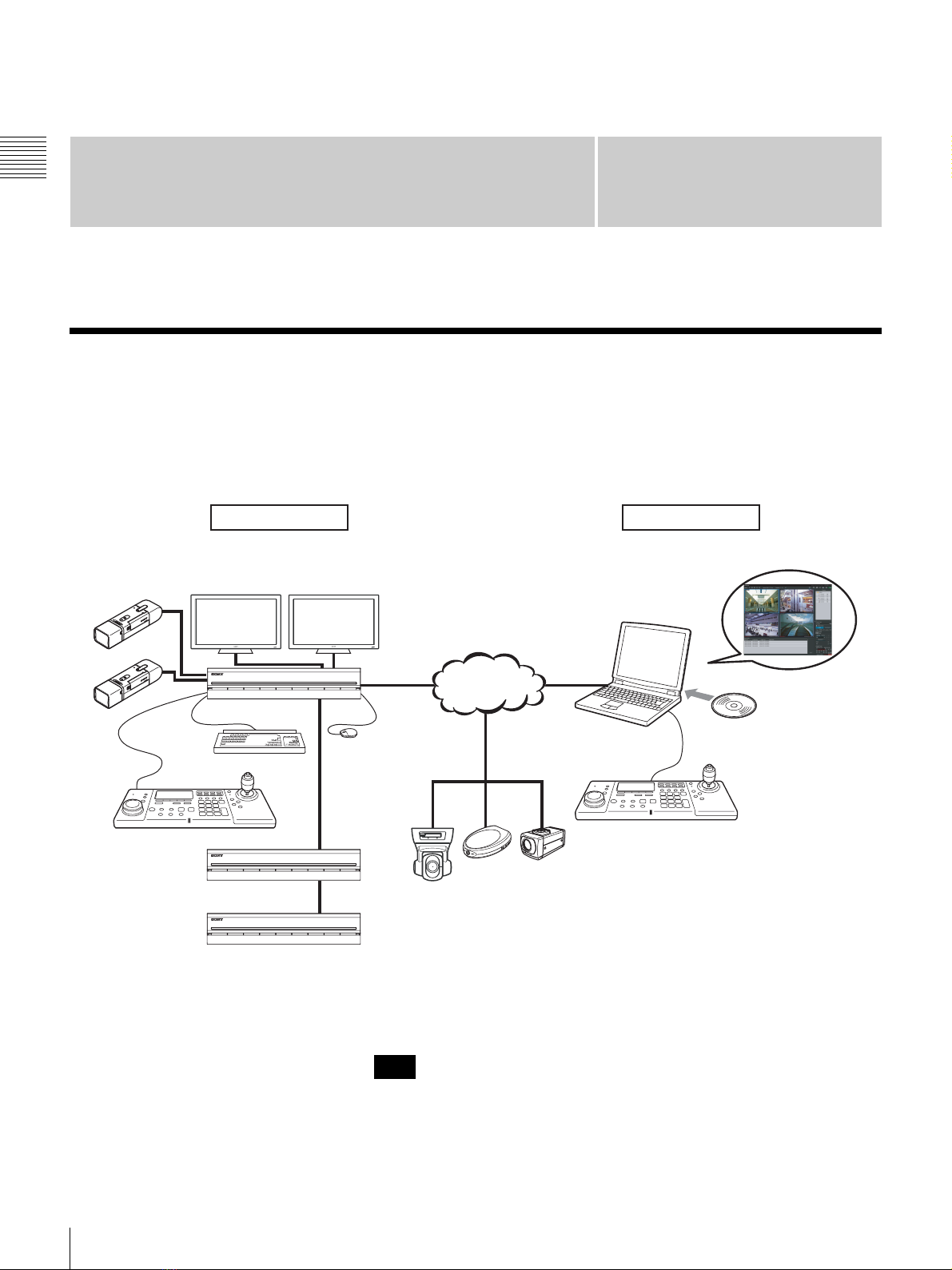
Control compatible cameras from remote
locations
You can pan, tilt, and perform zoom operations of
compatible cameras.
Compatible with analog cameras
You can monitor and record images from analog cameras
by connecting them directly to the unit1)
.
1) The NSR-1200/1100 requires an NSBK-A16 (optional)
expansion, while the NSR-1050H has a built-in connector.
Large-capacity hard disks allow recording for
long periods of time
Equipped with large-capacity hard disks, the unit is
capable recording high-quality images for extended
periods of time. For reference examples, see “Reference
Data for Installation” (page 11).
Slim type (2U), space-saving 19-inch rack
mounting model
With the optional rack mounting kit (sold separately), the
unit can be installed in a standard universal pitch EIA 19-
inch rack.
High-resolution up to 480 fps (VGA, JPEG)
recording
The NSR-1200 can support up to 64 cameras, the NSR-
1100 can support up to 32 cameras, and the NSR-1050H
can support up to 20 cameras. The NSR-1200 records
images at a total frame rate of 480 fps
1)
(240 fps with the
NSR-1100, 120 fps with the NSR-1050H) in VGA
resolution (640 × 480 pixels)
2)
and JPEG image format (1
frame about 31 KB) for a crisp image quality.
1) Maximum frame rate when 16 cameras are connected to the
recorder. Each camera has a frame rate of approximately 30
fps. This frame rate may become less because of
fragmentation on the internal hard disks. Values are based on
Sony measurements. These values are not guaranteed, as
performance may change due to the user’s operating
environment.
2) In QuadVGA resolution (1,280 × 960), the frame rate is 1/4
that of VGA resolution.
High reliability
The NSR-1200 supports RAID 5
1)
and peforms with high
reliability. The system can continue functioning even if
one of the hard disks develops a malfunction. The NSR
also supports uninterruptible power supplies (UPS)2),
making them extremely reliable systems.
1) RAID 5 is a system for dividing and storing data and parity
(error correcting codes) onto more than one hard disk drive.
Although this system allows continued operation should one
of the hard disks malfunction, it does not guarantee restoration
of lost data. In addition, due to high internal processing loads
during reconstruction after you replace the malfunctioned
hard disk, the unit may not be able to record images at the
configured recording rate while reconstruction is in progress.
2) If the power turns off suddenly during operation, the data may
be corrupted. In particular, when using the unit together with
an NSRE-S200 or other expansion storage, use a UPS.
Other features
• Custom layout support allows you to display images in a
variety of different layouts in addition to standard 2 × 2
and 3 × 3 layouts.
• The NSR is capable of manual, scheduled, and alarm
recording, among others.
• The NSR is equipped with a motion detection function
via the recorder1) (Video Motion Detection (Recorder)).
• Run searches for recorded images by camera name, date,
alarm, and other methods.
• Create privacy zones by using the dynamic masking
functions2). Dynamic masking covers pan, tilt, and
zoom.
• Precise alarm processing is made possible by performing
the various types of filtering3) that use the image
processing results sent from the camera in the form of
object information metadata. Because filtering can be
applied to metadata that has already been recorded, you
can also search for areas of interest after recording is
finished.
• Audio recording and playback4) are also supported from
compatible cameras.
1) Some functions are limited depending on the number of
cameras connected.
2) Some functions are limited depending on which camera
models are connected.
3) To perform motion detection and object detection using
metadata, a camera that supports motion detection by
metadata is required. The use of metadata is supported for up
to 32 cameras.
4) Optional audio amplifiers or speakers are required.

8Features and Functions
Chapter 1 Introduction
Features and Functions
Front (When the Cover is Opened)
NSR-1200/1100/1050H
APower LED
Lights green when the unit is turned on.
Lights amber when it is on standby.
BNetwork LED (1 to 3)
Lights green when there is activity at the
corresponding LAN connector at the rear of the NSR.
CHDD LED
Blinks green when the internal hard disks are accessed.
Lights amber when an error occurs with a hard disk.
DStatus LED (1 to 4)
Lights in sequence (1, 2, 3, 4) when the NSR starts.
When an error occurs, the corresponding status LED
lights together with the error LED, which lights or
blinks to indicate the type of error.
For details, see “STATUS LED” (page 133).
EError LED
Lights or blinks when an error occurs.
FREC LED
Lights when recording images.
GDVD/CD drive
Use this drive to write data from the NSR hard disks to
DVD and CD.
HUSB connector
Use this connector to connect a USB keyboard, USB
mouse, USB flash memory, or System Controller
(RM-NS1000) to the NSR.
IMonitor connector 1
Use this connector to connect a monitor.
Monitor connector 1 (and monitor connector 1 on the
rear of the unit) and HDMI monitor connector 1 on the
rear of the unit cannot be used at the same time.
JPower switch
Press this to turn on the unit. (You cannot turn off the
unit with this switch.)
KLock
Use this in conjunction with the supplied front panel
key to lock the front bezel. When the front bezel is
locked, you cannot pull out the front bezel. Also, do
not lock the front bezel when the front bezel is pulled
out. You can distinguish the locked position from the
unlocked position by looking at the lock, as illustrated
below.
LVent holes
These openings allow air to flow from the front of the
NSR to the rear.
Do not block the vent holes, allow dust to accumulate
in the inner mesh of the vent holes, or obstruct the
airflow in any way. Obstructing the airflow allows
heat to build up inside the NSR and may result in fire
or damage.
POWER 123NETWORK 1 2 3 4HDD 1 2 3 4 ERRORSTATUS REC
12345 6
708q
a
9q
s
The front bezel is
locked
The front bezel is
unlocked

9
Features and Functions
Chapter 1 Introduction
Rear
NSR-1200/1100
NSR-1050H
AFan
Take care not to obstruct the fan grille. If the grille is
obstructed, heat may build up in the unit, leading to
damage and/or fire.
BPower switch
Press the switch in the 1position to turn on the unit.
CRS-232C Connector
Use this connector to control analog cameras.
This connector cannot be used at the same time as the
RS-422/485 connector (four rightmost pins on F
alarm output connector).
DUPS connector (RS-232C)
Use this connector to connect the control line of the
uninterruptible power supply (UPS).
Additional configuration is necessary to perform
automatic shutdown with the UPS. Select [Enable] in
the UPS screen of the Setup Menu, and configure the
protocol according to the UPS in use. For details, see
“Setting Items of UPS Screen” (page 19).
ESensor input connector
Use this connector to connect the sensor input lines.
For connection details and wiring diagrams for sensor
inputs, see “I/O Port” (page 131).
FAlarm output connector
Use this connector to connect the alarm output lines.
For connection details and a wiring diagram for alarm
output, see “I/O Port” (page 131).
GHDMI monitor connectors (1 and 2)
Use these connectors to connect monitors that support
HDMI input.
HDMI monitor connector 1 and Lmonitor connector
1 (and monitor connector 1 on the front of the unit)
cannot be used at the same time, while HDMI monitor
connector 2 and Lmonitor connector 2 cannot be
used at the same time.
2316547
8
9qs 0qaqdqf
2316547qg
8q
s
q
a
90q
d
q
f

10 System Requirements
Chapter 1 Introduction
HAudio input connector (Used for future expansion)
Use this connector to input audio from a peripheral
audio device, such as a microphone.
Plug-In Power microphones are supported.
IMini-SAS output connector
Use this connector to connect the mini-SAS cable used
for connecting an NSRE-S200.
The NSRE-S200 is an optional expansion storage unit.
JUSB connector
Use this connector to connect a USB keyboard, USB
mouse, USB flash memory, or System Controller
(RM-NS1000) to the NSR.
KLAN connectors (1 to 4)
Use these connectors to connect 10 Base-T, 100 Base-
TX, or 1000 Base-T network cables.
LAN1: Network cameras1)
LAN2: Network cameras1) (LAN2 can only be used
when using a different segment from LAN1.)
1) Connect remote clients to the network specified with the [Network
Interface for Remote Client] setting (either LAN1 or LAN2) in the
Server Configuration screen. For details on the Server
Configuration screen, see “Configuring Settings Related to
Servers” (page 20).
LAN3: Used for iSCSI storages2)
LAN4: Used for iSCSI storages2)
2) For details on using iSCSI storage, contact your Sony dealer.
LMonitor connectors (1 and 2)
Use these connectors to connect a monitor.
Monitor connector 1 (and monitor connector 1 on the
front of the unit) and HHDMI monitor connector 1
cannot be used at the same time, while monitor
connector 2 and HHDMI monitor connector 2 cannot
be used at the same time.
MAudio output connectors (L and R)
Use these connectors to output audio to a peripheral
audio device.
NPower supply connector
Use this connector to connect the power cord.
OAnalog camera cable input connector
Use this connector to connect analog cameras via the
analog camera input cable.
The NSR-1050H is standard equipped with this
connector, but the NSR-1200/1100 requires an NSBK-
A16 (optional) expansion.
System Requirements
The hardware required in order to use this recorder are as
follows.
• Network cameras
Contact your dealer for details about compatible
network cameras.
• Monitor1)
• USB keyboard2)
•USBmouse
3)
• USB remote controller4)
•Networkswitch
• 1000Base-T/100Base-TX/10Base-T cable
• USB memory device5)
1) This unit supports HDMI-compatible devices and computer
displays that support RGB input.
The following resolutions can be specified.
- Full High-Definition (1,920 × 1,080)
- WUXGA (1,920 × 1,200)
- Full Wide XGA (1,360 × 768)
- UXGA (1,600 × 1,200)
- SXGA (1,280 × 1,024)
- XGA (1,024 × 768)
2) Use a USB keyboard with a cable. However, keys other than
the standard may not function. Wireless or infrared USB
keyboards may also not function properly.
3) Use a USB mouse with a cable. However, three-button or
wheel mice may not function properly. Wireless or infrared
USB mice may also not function properly.
4) You can use a remote controller to control pan, tilt, and zoom
operations for cameras.
- This unit supports RM-NS1000 System Controller and IP
Desktop USB controllers from CH Products. Other remote
controllers are not supported. Do not connect more than one
remote controller.
5) Required when backing up system information such as logs.
- This unit supports standard USB 2.0 Mass Storage devices.
Depending on the type of USB 2.0 Mass Storage device,
however, errors may occur when writing data to the device.
If errors occur when writing data, use a USB memory
device of a different type.

11
Reference Data for Installation
Chapter 1 Introduction
Reference Data for
Installation
Current Consumption and Inrush
Current
mini-SAS cable (accessory of NSRE-S200):
SONY Part No. 9-885-130-46
Storage Capacity for Recorded Data
You can confirm the configurations and the hard disk drive
capacity of the NSR-1200/1100/1050H and optional
expansion storage1) by clicking [Information] in the NSR-
1000 series logon screen, and viewing the Information
screen that appears. You can also confirm the actual
storage capacity2) to which data can be recorded in the
[Storage] tab of the Server screen.
1) Capacities for hard disk drives are approximations based on
the following equation for 1 GB: 1,000 × 1,000 × 1,000 =
1,000,000,000 bytes
2) Storage capacities are approximations based on the following
equation for 1 GB: 1,024 × 1,024 × 1,024 = 1,073,740,000
bytes
Number of Cameras
Maximum number of cameras
Maximum number of analog cameras (included in
total number of cameras)
Maximum number of audio channels
Model AC input
voltage
Full loading Inrush
current
NSR-1200 100 V 2.66 A
13 A
220 V 1.14 A
NSR-1100 100 V 1.84 A
220 V 0.79 A
NSR-1050H 100 V 1.75 A
220 V 0.76 A
NSRE-S200 100 V 0.79 A
220 V 0.34 A
Model Maximum number of cameras
NSR-1200 64
NSR-1100 32
NSR-1050H 20
Model Maximum number of analog cameras
NSR-1200 16 (with optional NSBK-A16)
NSR-1100 16 (with optional NSBK-A16)
NSR-1050H 16
Model Maximum number of audio channels
NSR-1200 64
NSR-1100 32
NSR-1050H 20

12 Overview / Displaying the Administration Menu
Chapter 2
Administration Menu
Chapter2
Administration Menu
Overview
The Administration Menu allows you to change settings
that were configured with the Setup Wizard when you
turned on the NSR for the first time, and also allows you to
perform configurations and operations related to the
server.
This chapter describes the following configurations and
operations for the Administration Menu.
•“Displaying the Administration Menu” (page 12)
•“Changing Initial Settings with the Setup Menu”
(page 13)
•“Configuring Settings Related to Servers” (page 20)
•“Installing Patch Files” (page 22)
•“Saving and Restoring Configuration Data” (page 23)
•“Exporting System Information” (page 25)
For details on restart and shutdown procedures, see
Chapter 3 “Shutting Down and Restarting the NSR”
(page 31).
Displaying the
Administration Menu
1
Enter the user name and password in the logon screen,
and click [Administration Menu].
If you are already logged on to the NSR, you can
display the logon screen by clicking at the top
right of the Main screen and logging off from the
dialog box that appears.
The Administration Menu screen appears.
Note
Note

13
Changing Initial Settings with the Setup Menu
Chapter 2
Administration Menu
Changing Initial Settings
with the Setup Menu
Use the Setup Menu to change settings that were
configured with the Setup Wizard when you turned on the
NSR for the first time.
Displaying Setup Menu
1
Click [Setup Menu] in the Administration Menu.
The menu items of the Administration Menu differ
depending on the server and clients.
The Setup Menu appears.
2
Select the item you want to configure, and click
[Select].
The screen corresponding to the item appears.
Details on Setting Items
Setting Items of Language Screen
Select the language to display on the screens, and click
[OK].
Setting Items of Keyboard Screen
Select the language of the USB keyboard connected to
NSR, and click [OK].
Setting Items of Date and Time Screen
Configure the date and time of the equipment, and click
[OK].
Year/Month/Day
Enter the date.
Hour/Min
Enter the time.

14 Changing Initial Settings with the Setup Menu
Chapter 2
Administration Menu
Date Format
Select the format for the date and time.
Enable NTP Server
Select the check box to enable the NTP server of NSR.
Synchronize with NTP Server
Select the check box to obtain the current time from
another NTP server.
IP Address
Enter the IP address of the NTP server from which to
obtain the information.
Synchronize with Windows Server
When a Windows server is used as the NTP server,
select the check box when synchronization of the time
is not possible.
Selecting this check box forces the time to be
synchronized with the Windows NTP server.
Current Synchronization
This displays the IP address of the NTP server from
which the current information is being obtained.
Time Zone
Select the region to configure the date and time.
There is no setting for enabling or disabling daylight
saving time. If you select a time zone in which daylight
saving time is observed, the clock is adjusted
automatically for daylight saving time.
Setting Items of Network Device Menu
Screen
The network settings consist of “General Network” for
setting general settings, and “Network Device 1 to 3” for
setting LAN connectors.
Select the network you want to configure, and click [OK].
Connect the following devices to the LAN connectors.
LAN1: Network camera1)
LAN2: Network cameras1) (LAN2 can only be used when
using a different segment from LAN1.)
1) Connect remote clients to the network specified with the [Network
Interface for Remote Client] setting (either LAN1 or LAN2) in the Server
Configuration screen. For details on the Server Configuration screen, see
“Configuring Settings Related to Servers” (page 20).
LAN3: iSCSI storage2)
2) For details on using iSCSI storage, contact your Sony dealer.
xSetting Items of General Network Screen
Configure each item, and click [OK].
Primary DNS
Enter the IP address for the primary DNS (Domain Name
Server).
Do not enter this if there is no primary DNS, or if it is not
required.
Secondary DNS
Enter the IP address for the secondary DNS. Do not enter
this if there is no secondary DNS, or if it is not required.
Default Gateway
Enter the IP address for the default gateway. Do not enter
this is if there is only a local network or there is no need to
connect to another network.
Hosts
If there is a special need to register a host name for the host
file, enter a combination of the IP address and host name,
and click [Add] to add the host to the list.
xSetting Items of Network Device 1 to 3
Configure each item, and click [OK].
Configure the settings as follows in accordance with your
environment.
Note
Caution

15
Changing Initial Settings with the Setup Menu
Chapter 2
Administration Menu
To use a DHCP to obtain the address setting automatically:
Select [DHCP].
To configure the address setting manually:
1Click [Static].
2Enter the following address.
IP Address
Enter the IP address.
• Before you enter the IP address, make sure there is
no machine that uses the same value on the same
network. Even if a machine that uses the same value
does exist, an error message will not be displayed.
However, be careful because more than one machine
using the same value will result in incorrect
operation.
• Even if you set an IP address that is prohibited under
the IP address assignment rules, it will not be
reflected in the system.
Example: 224.0.0.0 to 255.255.255.255
0.0.0.0
127.0.0.1, etc.
Netmask
Enter the subnet mask.
The default values for a network device are shown
below.
IP Address: 192.168.[0/1/2]1).1
Netmask: 255.255.255.0
1) The setting values for each of the network devices [#1/#2/
#3].
Route Setting
Click this when you need to configure the route to
another network.
Configure the settings as follows on the Route For
Network Device 1 screen that appears.
1Enter the address, gateway, and netmask of the
other network to which to connect, and click [Add]
to add the network to the list.
For details, contact the administrator of the network
to which you will connect.
2Click [OK].
Setting Items of Monitor Menu Screen
Select the monitor you want to configure, and click
[Select].
When you want to use two monitors connected to NSR,
selecting the [Dual Head] check box allows you to
configure the second monitor.
After you configure the second monitor, the system needs
to be restarted while the second monitor is connected.
xSetting Items of Monitor 1 to 2
Select the type and resolution of the monitor connected to
this equipment, and click [OK].
If you select [Auto], the type and resolution of the
connected monitor is detected and the setting is configured
automatically.
When an HDMI monitor is connected, the image may be
compressed to fit the screen and text may appear blurry.
You may be able to improve the image quality by selecting
the [Dot By Dot] check box so that each pixel of image
data is displayed as one dot on the monitor, without
expansion or compression processes. You may also need
to configure settings on the monitor side. Refer to the
operating instructions for your monitor.
Caution
Note
Caution
Note

16 Changing Initial Settings with the Setup Menu
Chapter 2
Administration Menu
Setting Items of Audio Screen
Select the audio connector you want to use, and click
[OK].
Setting Items of Disk Menu Screen
Select the operation for the hard disk drive, and click
[Select].
xSetting Items of Disk Installation Screen
Select the hard disk drive you want to operate, and click
[Select].
xSetting Items of Internal Disk Partition Screen
Configure the partitions of the internal hard disk drive, and
click [OK].
Capacity
This displays the capacity of the internal hard disk drive.
Raid Level
This displays the RAID type.
Number of Partitions
Select the number of partitions.
Partition1 [data1-1]
Select the size to allocate each partition as a percentage.
xSetting Items of SAS Disk List Screen
Select the NSRE-S200 for which you want to configure the
partition settings, and click [Partition]. When you have
finished configuring the settings, click [OK].
(This screen is only displayed when an NSRE-S200 is
connected.)
When an NSRE-S200 is connected, use a UPS.
Caution

17
Changing Initial Settings with the Setup Menu
Chapter 2
Administration Menu
xSetting Items of SAS Disk Partition Screen
Configure the partitions of the internal hard disk drive of
NSRE-S200, and click [OK].
Capacity
This displays the capacity of the internal hard disk drive.
Number of Partitions
Select the number of partitions.
Partition1 [data1-1]
Select the size to allocate each partition as a percentage.
xSetting Items of Disk Uninstallation Screen
Select the hard disk drive you want to delete, and click
[Uninstall]. When you have finished configuring the
settings, click [OK].
If you uninstall a hard disk, all of the data on the hard disk
will be deleted.
In particular, if you uninstall a hard disk drive that has
multiple partitions, multiple logical volumes registered on
the [Storage] tab of the Server Configuration screen will be
deleted automatically. Before you uninstall a hard disk,
check the [Storage] tab to confirm whether it is alright to
delete the registered storage.
For details on the [Storage] tab of servers, refer to
“Configuring Settings Related to Storage” (page 72).
Setting Items of FTP Screen
Configure each of the items when you want to enable the
FTP server, and click [OK].
Enable user to Get Data from Remote
Select the check box to enable remote client downloading
of recorded data using FTP.
If you select this check box, set the password.
User Name
This displays the user name. The user name is
“ftpadmin.”
It cannot be changed.
Password
Enter the password.
Enable user to Get Tools from Remote
Select the check box to enable remote client downloading
of tools, operating manuals, and other documents using
FTP.
This is enabled under default settings.
User Name
This displays the user name. The user name is
“ftptool.”
It cannot be changed.
Password
Enter the password. The default password is “ftptool.”
The user name and default password are both
“ftptool.”
Caution
Note

18 Changing Initial Settings with the Setup Menu
Chapter 2
Administration Menu
Setting Items of Server Name Screen
Enter the server name of NSR, and click [OK].
If you do not set a server name, NSR appends the last four
digits of the MAC address of the computer on which it is
installed to a default name, such as “NSR1050_DB12”.
Setting Items of SNMP Menu Screen
Select [Agent] when configuring an SNMP community,
and [Traps] when configuring an SNMP trap, and click
[OK].
xSetting Items of SNMP Agent Screen
Configure each item, and click [OK].
Enable
Select this to enable the SNMP agent function.
Disable
Select this to disable the SNMP agent function.
Community
Enter the SNMP community name.
Contact
Enter the contact.
Normally, enter the mail address of the system
administrator.
Location
Enter the installation location of NSR.
The MIB-2 object of “System” or “SystemUptime”
indicated with the object ID “.1.3.6.1.2.1.1” or
“.1.3.6.1.2.1.25.1.1” can be obtained.
xSetting Items of SNMP Traps Screen
Configure each item, and click [OK].
Enable
Select this to enable the SNMP traps function.
Disable
Select this to disable the SNMP traps function.
Host IP Address
Enter the IP address of the traps host.
Community
Enter the SNMP community name.
Shutdown Events
Notify when the NSR shuts down.
Temperature Events
Notify when the temperature of NSR rises.
Voltage Events
Notify when the voltage is abnormal.
Fan Events
Notify when the fan is abnormal.
UPS Events
If a UPS is connected, notify when the UPS has detected a
power cut, and when the UPS has detected recovery from
the power cut.
Power Events
Notify when a power malfunction occurs.
Note
Note

19
Changing Initial Settings with the Setup Menu
Chapter 2
Administration Menu
HDD Events
Notify when a hard disk drive malfunctions.
RAID Events
Notify when a RAID group rebuilds.
File System Event
Notify when a file system malfunction occurs.
Network Events
Notify when a network device malfunction occurs.
Resource Usage Events
Notify when the management domain of the hard disk
drive or percentage of CPU used is abnormally high.
SAS Events
Notify when a connected NSRE-S200 malfunctions.
Setting Items of UPS Screen
Configure settings related to UPS, and click [OK].
Enable
Select this when using a UPS.
If this is selected, select the type of UPS to be used from a
list of UPS.
If the power turns off suddenly during operation, the data
may be corrupted. In particular, when using the unit
together with an NSRE-S200 or other expansion storage,
use a UPS.
Disable
Select this when not using a UPS.
Power off in XXX Seconds
Enter the time from when a power cut is detected until
shutdown to start.
For details on automatic startup after power is restored,
contact your dealer.
Setting Items of Auto Logon Screen
When you want to enable the auto logon function, select
the [Enable Auto Logon] check box, and click [OK].
Setting Items of Serial Port (Analog
Camera) Screen
Configure settings related to the analog camera
connection.
Configure each item, and click [OK].
(This screen appears when an NSR-1050H or NSBK-A16
(option) is connected.)
Serial standard (RS-485, RS-422, RS-232C)
Select the serial standard for connecting to the analog
camera you want to control.
Baud rate
Select the communication baud rate.
Parity bit
Select the parity bit.
Character length
Select the character length.
Stop bits
Select the stop bits.
Caution
Caution

20 Configuring Settings Related to Servers
Chapter 2
Administration Menu
Setting Items of Video (Analog Camera)
Screen
Select the video format for the analog camera to be
connected, and click [OK].
(This screen appears when an NSR-1050H or NSBK-A16
(option) is connected.)
Configuring Settings
Related to Servers
Configure these settings when, for example, you want to
change the network settings to match the network
environment of the users, or you want to centralize user
administration when using multiple NSR and RealShot
Manager Advanced together.
1
Click [Server Configuration] in the Administration
Menu.
The menu items of the Administration Menu differ
depending on the server and clients.
The Server Configuration screen appears.
2
Configure each item, and click [OK].
Central Server Mode
Set this if you want to manage multiple NSRs and
RealShot Manager Advanced (Server) as one
system1), or you want to connect from RealShot
Manager Advanced (Client).
This manual suits for next models
2
Table of contents
Other Sony Security System manuals

Sony
Sony DVP-NW50 - In-wall Dvd Player User guide

Sony
Sony CCD-680E User manual

Sony
Sony CCTV Systems Manual

Sony
Sony SRG-301SE User manual

Sony
Sony XV-C900 User manual

Sony
Sony DVS-9000 User manual

Sony
Sony SNT-EP154 User manual

Sony
Sony SRG-300SE User manual

Sony
Sony Smarter Security User manual

Sony
Sony CCTV Systems Manual