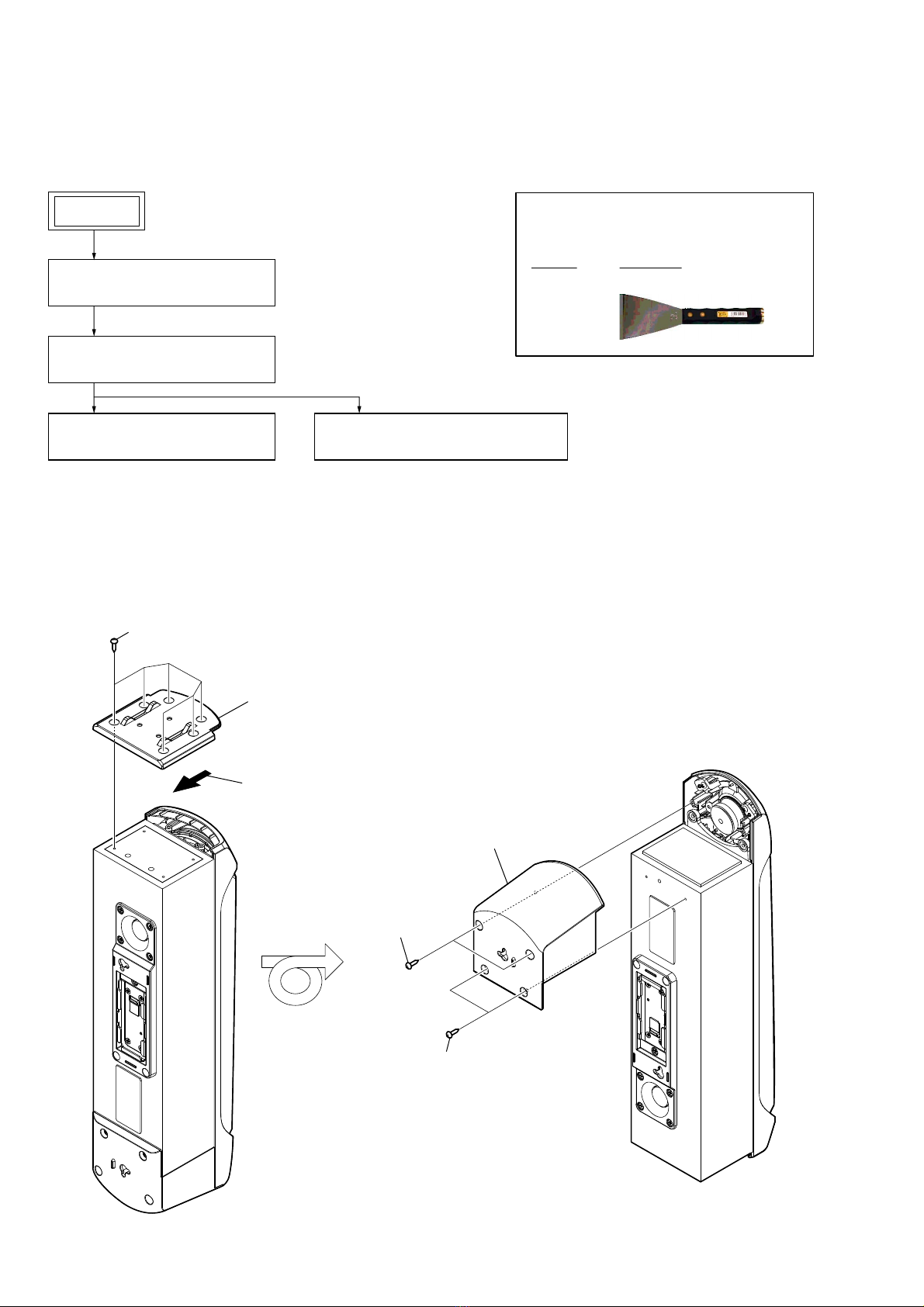
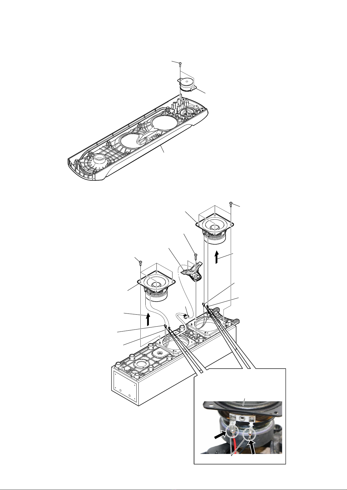
Sony SS-GT4DB User manual

SERVICE MANUAL
Sony Corporation
Published by Sony EMCS (Malaysia) PG Tec
SS-GT4DB
SPECIFICATIONS
SPEAKER SYSTEM
9-890-675-02
2016E80-1
© 2016.05
AEP Model
UK Model
E Model
Australian Model
Ver. 1.1 2016.05
• SS-GT4DB is Speaker system in MHC-GT4D.
• All of the units included in the MHC-GT4D (SS-
GT4DB, SA-WGT4D, Remote control) are required
to confirming operation of SS-GT4DB. Check in
advance that you have all of the units.
T
4D.
4
D
(SS
-
required
C
heck in
Speaker system
2-way, bass reflex
Speaker unit (left/right)
Tweeters: 40 mm × 1, cone type
Midrange: 80 mm × 2, cone type
Rated impedance
5 ohms
Design and specifications are subject to
change without notice.

SS-GT4DB
2
SECTION 1
DISASSEMBLY
• This set can be disassembled in the order shown below.
1-1. DISASSEMBLY FLOW
Note: Follow the disassembly procedure in the numerical order given.
1-2. FRONT PANEL SECTION-1
• Continued on 1-3 (page 3).
Note: L-ch and R-ch can be similarly disassembled.
The illustration of L-ch is used for explanation.
SET
1-2. FRONT PANEL SECTION-1
(Page 2)
1-3. FRONT PANEL SECTION-2
(Page 3)
1-4. LOUDSPEAKER (4cm) (SP3)
(Page 4)
1-5. LOUDSPEAKER (8cm) (SP1, SP2)
(Page 4)
JIG
When disassembling the unit, use the following
jig for speaker removal.
Part No. Description
J-2501-238-A JIG FOR SPEAKER REMOVAL
– Rear top view –
– Rear bottom view –
4two screws
((1) (3.5 u14), TAPPING)
1six screws
((1) (3.5 u14), TAPPING)
4two screws
((1) (3.5 u14),
TAPPING)
5top panel (L) section
3bottom panel (L) section
2Remove the bottom panel (L) section
in the direction of the arrow.

SS-GT4DB
3
1-3. FRONT PANEL SECTION-2
8front panel section
Note 3: When installing the front panel section,
remove the used glue and use a new
glue to fix the front panel section.
– Bottom view –
2Insert a flat-head screwdriver into
the front panel section, and lift it a little.
2Insert a flat-head screwdriver into
the front panel section, and lift it a little.
3 Insert the jig into a space and raise
front panel section.
Note 1: When using a jig, please work so
as not to injure front panel section
and speaker cabinet.
3 Insert the jig into a space and raise
front panel section.
Note 1: When using a jig, please work so
as not to injure front panel section
and speaker cabinet.
4 All bosses are removed while moving jig in the
direction of the arrow, and front panel section is removed.
4 All bosses are removed while
moving jig in the direction of
the arrow, and front panel
section is removed.
5Remove the front panel section
in the direction of the arrow.
7terminal
(narrow side)
7terminal
(wide side)
:LUHVHWWLQJ
6Push the protrusion, and remove
the terminal.
protrusion
loudspeaker (4cm)
(SP3)
Push
total ten bosses
Push
1two screws
((1) (3.5 u14), TAPPING)

SS-GT4DB
4
1-4. LOUDSPEAKER (4cm) (SP3)
1-5. LOUDSPEAKER (8cm) (SP1, SP2)
3front panel section
– Rear bottom view –
1two screws
(+BVTP 3 u10)
2loudspeaker (4cm)
(SP3)
4four screws
(3.5 u12)
4four screws
(3.5 u12)
1two screws
(+BV TAPPING TYPE-1 3.5)
2CN1600
(7P)
5Remove the loudspeaker (8cm) (SP2)
section in the direction of the arrow.
5Remove the loudspeaker
(8cm) (SP1) section in
the direction of the arrow.
8loudspeaker (8cm) (SP1)
3LED bracket section
8loudspeaker (8cm) (SP2)
7terminal
(narrow side)
7terminal
(narrow side)
7terminal
(wide side)
7terminal
(wide side)
:LUHVHWWLQJ
Push
protrusion
loudspeaker (8cm)
Push
–7RSYLHZ–
6Push the protrusion, and remove
the terminal.

5
SS-GT4DB
SECTION 2
DIAGRAMS
For Schematic Diagrams.
Note:
• C: panel designation.
•Signal path
F: AUDIO
THIS NOTE IS COMMON FOR PRINTED WIRING BOARDS AND SCHEMATIC DIAGRAMS.
(In addition to this, the necessary note is printed in each block.)
For Printed Wiring Boards.
Note:
• X: Parts extracted from the component side.
• : Pattern from the side which enables seeing.
(The other layers' patterns are not indicated.)
2-1. PRINTED WIRING BOARD – BAR_RGB_A, BAR_RGB_B Board (LEFT) –
• : Uses unleaded solder.
2-2. SCHEMATIC DIAGRAM – BAR_RGB_A, BAR_RGB_B Board (LEFT) –
1
A
B
C
D
E
2345678
CL1600
CL1601
CL1602
CL1603
17
89
CN1600
14
56
CN1601
D1600
14
56
CN1650
CL1650
CL1651
CL1652
CL1653
D1650
BAR_RGB_A BOARD
(LEFT)
BAR_RGB_B BOARD
(LEFT)
1-980-567-
11
(11)
1-980-566-
11
(11)
RGB_SPLITTER BOARD
CN1251
SA-WGT4D
(Page 46)
>010P
1
A
B
C
2345678
BAR_RGB_A BOARD
(LEFT)
BAR_RGB_B BOARD
(LEFT)
GRN
RED
BLU
CL1602
CL1603
CL1600
CL1601
D1600
DI_LTRB R8SF
CN1601
4P
1 BAR_B_GREEN_LED
2 BAR_B_RED_LED
3 BAR_B_BLUE_LED
4 M+5.2V
CN1600
7P
1BAR_R_B_GREEN_LED
2BAR_R_B_RED_LED
3BAR_R_B_BLUE_LED
4BAR_R_A_GREEN_LED
5BAR_R_A_RED_LED
6BAR_R_A_BLUE_LED
7M+5.2V
>005S
RGB_SPLITTER
BOARD
CN1251
SA-WGT4D
(Page 47)
GRN
RED
BLU
CL1652
CL1653
CL1650
CL1651
CN1650
4P
1M+5.2V
2BAR_B_BLUE_LED
3BAR_B_RED_LED
4BAR_B_GREEN_LED
D1650
DI_LTRB R8SF

6
SS-GT4DB
2-3. PRINTED WIRING BOARD – BAR_RGB_A, BAR_RGB_B Board (RIGHT) –
• : Uses unleaded solder.
2-4. SCHEMATIC DIAGRAM – BAR_RGB_A, BAR_RGB_B Board (RIGHT) –
1
A
B
C
D
E
2345678
CL1600
CL1601
CL1602
CL1603
17
89
CN1600
14
56
CN1601
D1600
14
56
CN1650
CL1650
CL1651
CL1652
CL1653
D1650
BAR_RGB_A BOARD
(RIGHT)
BAR_RGB_B BOARD
(RIGHT)
1-980-567-
11
(11)
1-980-566-
11
(11)
RGB_SPLITTER BOARD
CN1252
SA-WGT4D
(Page 46)
>011P
1
A
B
C
D
E
2345678
BAR_RGB_A BOARD
(RIGHT)
BAR_RGB_B BOARD
(RIGHT)
GRN
RED
BLU
CL1602
CL1603
CL1600
CL1601
D1600
DI_LTRB R8SF
CN1601
4P
1 BAR_B_GREEN_LED
2 BAR_B_RED_LED
3 BAR_B_BLUE_LED
4 M+5.2V
CN1600
7P
1BAR_R_B_GREEN_LED
2BAR_R_B_RED_LED
3BAR_R_B_BLUE_LED
4BAR_R_A_GREEN_LED
5BAR_R_A_RED_LED
6BAR_R_A_BLUE_LED
7M+5.2V
>006S
RGB_SPLITTER
BOARD
CN1252
SA-WGT4D
(Page 47)
GRN
RED
BLU
CL1652
CL1653
CL1650
CL1651
CN1650
4P
1M+5.2V
2BAR_B_BLUE_LED
3BAR_B_RED_LED
4BAR_B_GREEN_LED
D1650
DI_LTRB R8SF

7
SS-GT4DB
SECTION 3
EXPLODED VIEW
1 4-874-614-12 SCREW (1) (3.5X14), TAPPING
2 A-2090-521-A PANEL (L) ASSY, TOP
2 A-2090-522-A PANEL (R) ASSY, TOP
3 4-874-614-02 SCREW (1) (3.5X14), TAPPING
4 A-2090-518-A PANEL ASSY, FRONT
5 4-874-614-82 +BV TAPPING SCREW TYPE-1 3.5
6 3-269-307-01 SCREW 3.5X12 BIND AB
7 A-2085-940-A BAR_RGB_A BOARD, COMPLETE
8 A-2085-941-A BAR_RGB_B BOARD, COMPLETE
9 4-581-519-01 PANEL (L), REAR
10 1-849-250-13 CABLE WITH CONNECTOR
(LA9, AR, E4, EA, E12, TH)
10 1-849-250-31 CABLE WITH CONNECTOR
(AEP, UK, AUS, RU, MY)
11 4-581-520-01 PANEL (R), REAR
12 1-849-250-23 CABLE WITH CONNECTOR
(LA9, AR, E4, EA, E12, TH)
12 1-849-250-41 CABLE WITH CONNECTOR
(AEP, UK, AUS, RU, MY)
SP1 1-859-168-11 LOUDSPEAKER (8CM)
SP2 1-859-168-11 LOUDSPEAKER (8CM)
SP3 1-859-178-11 LOUDSPEAKER (4CM)
#1 7-685-647-79 SCREW +BVTP 3X10 TYPE2 IT-3
#2 7-685-646-79 SCREW +BV 3X8, TYPE 2, IT-3
ns not supplied
Ref. No. Part No. Description Remark Ref. No. Part No. Description Remark
Note:
• -XX and -X mean standardized parts, so
they may have some difference from the
original one.
• Items marked “*” are not stocked since
they are seldom required for routine ser-
vice. Some delay should be anticipated
when ordering these items.
• The mechanical parts with no reference
number in the exploded views are not sup-
plied.
• Color Indication of Appearance Parts Ex-
ample:
KNOB, BALANCE (WHITE) . . . (RED)
Parts Color Cabinet’s Color
Note: This illustration is the exploded view of the left speaker.
The right speaker is different in the shape of some parts.
#1
#2
#2
SP3
SP1
SP2
ns ns
ns
ns
ns
ns ns
ns ns ns
ns
ns
ns
ns
ns
ns
ns
(Right speaker)
(Right speaker)
1
1
11
1
6
7
4
1
3
2
6
A
C
A
58
9
10
B
C
B
11
12
• Abbreviation
AR : Argentina model
AUS : Australian model
E4 : African model
E12 : 220 – 240 V AC area in E model
EA : Saudi Arabia model
LA9 : Latin-American model
MY : Malaysia model
RU : Russian model
TH : Thai model
Ver. 1.1

A-2085-940-A BAR_RGB_A BOARD, COMPLETE
**************************
< CONNECTOR >
CN1600 1-580-756-21 PIN, CONNECTOR (SMD) 7P
CN1601 1-580-057-11 PIN, CONNECTOR (SMD) 4P
< DIODE >
*D1600 6-503-912-01 DI_LTRB R8SF
************************************************************
A-2085-941-A BAR_RGB_B BOARD, COMPLETE
**************************
< CONNECTOR >
CN1650 1-580-057-11 PIN, CONNECTOR (SMD) 4P
< DIODE >
*D1650 6-503-912-01 DI_LTRB R8SF
8
SS-GT4DB
SECTION 4
ELECTRICAL PARTS LIST
When indicating parts by reference num-
ber, please include the board name.
Note:
• Due to standardization, replacements in
the parts list may be different from the
parts specified in the diagrams or the
components used on the set.
• -XX and -X mean standardized parts, so
they may have some difference from the
original one.
• RESISTORS
All resistors are in ohms.
METAL: Metal-film resistor.
METAL OXIDE: Metal oxide-film resistor.
F: nonflammable
• Items marked “*” are not stocked since
they are seldom required for routine ser-
vice.
Some delay should be anticipated when
ordering these items.
• SEMICONDUCTORS
In each case, u: μ, for example:
uA. . : μA. . , uPA. . , μPA. . ,
uPB. . : μPB. . , uPC. . , μPC. . ,
uPD. . : μPD. .
• CAPACITORS
uF: μF
• COILS
uH: μH
The components identified by mark 0
or dotted line with mark 0are critical for
safety.
Replace only with part number specified.
Ref. No. Part No. Description Remark
• Abbreviation
AR : Argentina model
AUS : Australian model
E4 : African model
E12 : 220 – 240 V AC area in E model
EA : Saudi Arabia model
LA9 : Latin-American model
MY : Malaysia model
RU : Russian model
TH : Thai model
BAR_RGB_A BAR_RGB_B
Ver. 1.1

MEMO
9
SS-GT4DB

SS-GT4DB
REVISION HISTORY
Ver. Date Description of Revision
1.0 2016.02 New
1.1 2016.05 Addition of African, Argentina, 220 – 240 V AC area in E model, Malaysia, Russian, Saudi Arabia and
Thai models.
How to search for a contact point of signal lines or the like in DIAGRAMS SECTION
If a contact point of a BLOCK DIAGRAM, PRINTED WIRING BOARD or SCHEMATIC DIAGRAM is shown in a different page, use
the PDF file search function to find one.
e.g.) If a contact point is shown as , follow the procedure below.
Procedure:
1. Press the [F] key while pressing the [Ctrl] key.
2. Input “>001Z” in the search box and press the [Enter] key.
3. The relevant part (page), where the contact point is shown, appears.
Note: If you still see the original page, press the [Enter] key again.
Table of contents
Other Sony Speakers System manuals

Sony
Sony SS-CT60AV User manual

Sony
Sony HT-CT800 User guide

Sony
Sony SRSDF30 - PC 2.1 Speakers User manual

Sony
Sony SS-CGPX5 User manual

Sony
Sony SAV-E325 User manual

Sony
Sony SRS-M50 User manual

Sony
Sony SRS-GD50iP User manual

Sony
Sony HT-NT5 User manual

Sony
Sony SS-CR350 User manual

Sony
Sony Operating Instructions SRS-D200 User manual

Sony
Sony HT-ST7 User manual

Sony
Sony HT-CT770 User guide

Sony
Sony PMC-R30L User manual

Sony
Sony PMC-DR45L User manual

Sony
Sony SA-WMT300 User manual

Sony
Sony WALKMAN SRS-NWGT10 User manual

Sony
Sony HT-ST7 User manual

Sony
Sony SRS-U10 User manual

Sony
Sony SS-SFCR505H Installation instructions manual

Sony
Sony SA-VA29 User manual