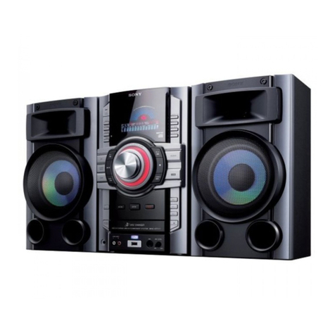
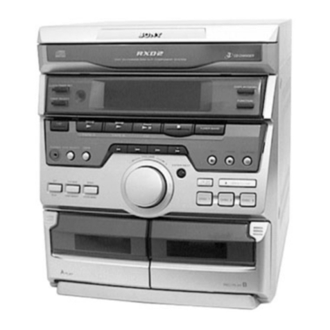
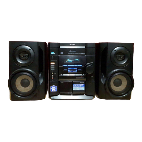
Sony CDP-SP55 User manual

1
CDP-SP55
SERVICE MANUAL
CDP-SP55 is the CD section in CMT-SP55MD
or CMT-SP55TC.
SPECIFICATIONS
MINI Hi-Fi COMPONENT SYSTEM
Model Name Using Similar Mechanism NEW
CD Mechanism Type CDM55C-K6BD38
Base Unit Type BU-K6BD38
Optical Pick-up Type KSM-213DCP/Z-NP
AEP Model
UK Model
E Model
General
Dimensions (w/h/d) Approx. 202 ×75 ×290 mm
Mass Approx. 1.5 kg
Design and specifications are subject to change
without notice.
System Compact disc and digital audio
system
Laser Semiconductor laser (λ=780 nm)
Emission duration: continuous
Laser output Max. 44.6 µW*
*This output is the value
measured at a distance of 200 mm
from the objective lens surface on
the Optical Pick-up Block with
7 mm aperture.
Frequency response 20 Hz – 20 kHz
Output
DIGITAL OPTICAL OUT: O
p
tical

2
TABLE OF CONTENTS
1. SERVICING NOTE ·························································· 4
2. GENERAL ·········································································· 6
3. DISASSEMBLY
3-1. Case ···················································································· 7
3-2. Front Panel Assy ································································· 7
3-3. CD Mechanism Deck (CDM55C-K6BD38) ······················ 8
3-4. Main Board ········································································· 8
3-5. CAM, GEAR ······································································ 9
3-6. Holder Assy ········································································ 9
3-7. Optical Pick-up ································································· 10
3-8. BD Board ·········································································· 10
4. ELECTRICAL ADJUSTMENT ·································· 11
5. DIAGRAMS
5-1. Circuit Boards Location ··················································· 14
5-2. Block Diagram ································································· 15
5-3. Printed Wiring Board –BD Section – ······························ 16
5-4. Schematic Diagram –BD Section – ································· 17
5-5. Printed Wiring Board –Main Section – ··························· 18
5-6. Schematic Diagram –Main Section – ······························ 19
5-7. Printed Wiring Board –Loading Section – ······················ 20
5-8. Schematic Diagram –Loading Section – ························· 20
5-9. IC Block Diagram ···························································· 20
6. EXPLODED VIEWS
6-1. Case and Front Panel Section ··········································· 22
6-2. CD Mechanism Deck Section (CDM55C-K6BD38) ······· 23
6-3. Base Unit Section (BU-6BD38) ······································· 24
7. ELECTRICAL PARTS LIST ······································· 25

3
This appliance is classified as a CLASS 1 LASER product. The
CLASS 1 LASER PRODUCT MARKING is located on the rear
exterior.
Laser component in this product is capable
of emitting radiation exceeding the limit for
Class 1.
CAUTION
Use of controls or adjustments or performance of procedures
other than those specified herein may result in hazardous radiation
exposure.
Notes on chip component replacement
•Never reuse a disconnected chip component.
•Notice that the minus side of a tantalum capacitor may be
damaged by heat.
Flexible Circuit Board Repairing
•Keep the temperature of soldering iron around 270˚C
during repairing.
•Do not touch the soldering iron on the same conductor of the
circuit board (within 3 times).
•Be careful not to apply force on the conductor when soldering
or unsoldering.
NOTES ON HANDLING THE OPTICAL PICK-UP
BLOCK OR BASE UNIT
The laser diode in the optical pick-up block may suffer electrostatic
break-down because of the potential difference generated by the
charged electrostatic load, etc. on clothing and the human body.
During repair, pay attention to electrostatic break-down and also
use the procedure in the printed matter which is included in the
repair parts.
The flexible board is easily damaged and should be handled with
care.
NOTES ON LASER DIODE EMISSION CHECK
The laser beam on this model is concentrated so as to be focused on
the disc reflective surface by the objective lens in the optical pick-
up block. Therefore, when checking the laser diode emission,
observe from more than 30 cm away from the objective lens.
MODEL IDENTIFICATION
— BACK PANEL —
• Abbreviation
AED : North European model
HK : Hong Kong model
MY : Malaysia model
SP : Singapore model
KR : Korea model
MODEL
AEP,UK,AED models
HK,MY,SP models
KR model
PARTS No.
4-229-674-0s
4-229-674-2s
4-229-674-3s
SAFETY-RELATED COMPONENT WARNING!!
COMPONENTS IDENTIFIED BY MARK 0OR DOTTED LINEWITH
MARK 0ON THE SCHEMATIC DIAGRAMS AND IN THE PARTS
LIST ARE CRITICAL TO SAFE OPERATION. REPLACE THESE
COMPONENTS WITH SONY PARTS WHOSE PART NUMBERS
APPEAR AS SHOWN IN THIS MANUAL OR IN SUPPLEMENTS
PUBLISHED BY SONY.
Parts No.

4
This unit cannot be repaired by itself.
When repairing, connect the whole system except for the speaker.
CDText Display
• This unit displays CD text.
Text is displayed for the first 50 track only and will not be displayed from the 51st track onwards. Do not suspect a fault in this case.
In some cases, some special characters will not be displayed and may be replaced by other characters. Do not suspect a fault in this case.
Cold Reset
• The cold reset clears all data including preset data stored in the RAM to initial conditions. Execute this mode when returning the set to the
customer.
Procedure :
1. When the power ON, press the ?/1button (TA) while pressing the TUNING MODE button (ST) and ML buttons (CDP)
together.
2. “COLD RESET” is displayed on the fluorescent indicator tube and reset is executed.
Hot Reset
• This mode reset the preset data kept in the memory. The hot reset mode functions same as if the power cord is plugged in and out.
Procedure :
1. When the power ON, press the ?/1button (TA) while pressing the TUNING MODE button (ST) and lm buttons (CDP)
together.
2. Turn off the unit and reset is executed.
GCTest Mode
Procedure :
1. When the power ON, press the ?/1button (TA) while pressing the TUNING MODE button (ST) and PLAY MODE buttons (CDP)
together.
2. Fluorescent indicator tube are all turned on.
3. Press TUNING MODE button (ST) to enter the model destination indecation mode. “SP55 CE2” appears.
4. Every pressing of TUNING MODE button (ST) changes the display in the following order.
MC Version tCD Version tST Version tTC Version tTA Version tTM Version tmodel destination display.
5. Press DISPLAY button (ST) and the date appears as “ 00615a ”
Every pressing of DISPLAY button (ST) changes the display in the Version display and model destination display.
6. Press TUNER/BAND button (ST) to enter the key check mode.
7. In the key check mode, the fluorescent indicator tube displays “Key 0 Vol 0”. Each time a button is pressed, “Key” value increases.
However, once a button is pressed, it is no longer taken into account.
“Vol” Value increases like “1, 2, 3 ...” if rotating VOLUME knob (TA) in the clockwise direction, or decreases like “0, 9, 8 ...” if rotating
in the counterclockwise diretion.
8. To exit from this mode, press three buttons in the same procedure as step 1, or disconnect the power cord.
SECTION 1
SERVICING NOTE

5
Aging Mode
• Mode for repeating operations of the CD player and TC deck automatically.
When errors occur:
Aging stops and a message indicating that an error has occurred such as “CD MEC ERR” is displayed.
(For details of errors, refer to “Error History Display Mode”.)
When no errors occur:
Aging is repeatedly performed.
Procedure:
1. Load any CD and a tape.
2. Select the function “ CD ” using the FUNCTION knob (TA).
3. While pressing the TUNING MODE button (ST) and Hbutton (CDP), press the ?/1button (TA).
4. “AGING” is displayed on the fluorescent display tube briefly.
5. Operations are performed in the following sequence during aging.
Every pressing of DISPLAY button (ST) changes the display in the CD display and TAPE display.
6. To end aging, execute the cold reset.
Error History Display Mode
Mode for checking the history of errors which have occurred in the CD player.
Execute this mode after ending the aging mode.
Procedure:
1. Select the function “ CD ” using the FUNCTION knob (TA).
2. While pressing the TUNING MODE button (ST) and Sbutton (CDP), press the ?/1button (TA).
3. “EMC@@EDC**” id displayed.
@@ : Number of mechanism errors (Last 3 errors)
** : Number of errors (NO DISC ERROR) which occurred after chucking (Last 3 errors)
4. To end, press the ?/1button (TA) and turn OFF the power.
Note: To erase the error history, perform cold reset.
(While pressing the TUNING MODE button (ST) and ML button (CDP), press the ?/1button (TA).)
CD : Cassette :
Reading of TOC
Playback of first track (3sec.)
Playback of last track (3sec.)
CD tray open
CD tray close
REW (Shut off) "TAPE AG-1"
PLAY
FF
REV PLAY
REW
(2 min) "TAPE AG-2"
(Shut off) "TAPE AG-3"
(2 min) "TAPE AG-4"
(Shut off) "TAPE AG-5"
(Shut off) "TAPE AG-6"
(Shut off) "TAPE AG-7"
"TAPE AG-8"
"TAPE AG-9"
(Shut off)
FF
REW
OPEN
CLOSE

6
SECTION 2
GENERAL
1PLAY MODE button
2REPEAT button
3Hbutton
4Sbutton
5sbutton
q; 9
1 2 3 4 5
7
6
8
6lm button
7ML button
8Abutton
9Sindicator
q; Hindicator
8
Step 2: Setting the time
You must set the time beforehand to use the timer
functions.
The clock is on a 24-hour system for the European
model, and a 12-hour system for other models.
The 24-hour system is used for illustration
purposes.
Set the time before turning on the system.
`/1
1
2,3
2,32,3
1
Press CLOCK/TIMER SET while the
system is off.
The hour indication flashes.
2
Press .or >to set the hour, then
press ENTER/YES.
The minute indication flashes.
3
Press .or >to set the minute,
then press ENTER/YES.
The clock starts.
If you made a mistake
Start over from step 1.
To change the preset time
You can change the preset time while the system
is on.
1Press CLOCK/TIMER SET.
2Press .or >repeatedly until “SET
CLOCK” appears, then press ENTER/YES.
3Repeat steps 2 and 3.
Tips
• The built-in clock shows the time in the display
while the system is off. If you press DISPLAY at
this time, the display back light lights up, making
the clock easier to see.
• The upper dot of the colon flashes for the first 30
seconds, and the lower dot flashes for the last 30
seconds of each minute.
This section is extracted from
instruction manual.

7
SECTION 3
DISASSEMBLY
3-1. CASE
3-2. FRONT PANEL ASSY
1two screws
(case 3 TP2
)
4case
1two screws
(case 3 TP2) 2
2
3
Set Case Front Panel Assy
CD Mechanism Deck (CDM55C-K6BD38)
Holder Assy Optical pick-up
Main Board (Page 8)
Cam, Gear
BD Board
(Page 9) (Page 10)
(Page 9)(Page 8)
(Page 10)
1connector
(CN711)
4screw (BVTP 3x12)
5front panel assy
2two screws
(BVTP 3x12)
3two foot assy's
claws
claws

8
3-3. CD MECHANISM DECK (CDM55C-K6BD38)
3-4. MAIN BOARD
2connector
(CN112)
3screw (BVTP 3x8)
two claws
5CD mechanism deck
41flat type wire (19 core
)
(CN713)
1screw (BVTP 3x8
)
2main board

9
3-5. CAM, GEAR
3-6. HOLDER ASSY
4belt (CDM55)
6pulley (LDG)
9gear (A)
8gear (B)
7roller
2Push the claw in tne
direction of arrow C.
0cam (CDM55)
3Pull out the tray.
5bushing
C
AB
BRelease
1Pull out the tray in the arrow direction A,
and release the lock while pressing
this claw in the arrow direction B.
2Remove the Holder (BU) ass
y
in the direction of arrow A.
A
1floating screw
(PTPWH M2.6)

10
3-7. OPTICAL PICK-UP
3-8. BD BOARD
3Optical pick-up
4flat type wire
(16 core)
1Release the lever in the
arrow direction B.
B
2sled shaft
IC102
IC101
M101
M102
IC103
2Remove the four solders.
1screw
(
BVTP 2.6x8
)
3BD board

11
Note :
1. CD Block is basically designed to operate without adjustment.
Therefore, check each item in order given.
2. Use YEDS-18 disc (3-702-101-01) unless otherwise indicated.
3. Use an oscilloscope with more than 10MΩimpedance.
4. Clean the object lens by an applicator with neutral detergent
when the signal level is low than specified value with the
following checks.
S-Curve Check
Procedure :
1. Connect oscilloscope to TP (FEO).
2. Connect between TP (FEI) and TP (VC) by lead wire.
3. Connect between TP (AGCCON) and TP (DGND) by lead wire.
4. Press the "/1 button (TA).
5. Load a disc (YEDS-18) and actuate the focus search. (In
consequence of open and close the disc tray, actuate the focus
search)
6. Confirm that the oscilloscope waveform (S-curve) is
symmetrical between A and B. And confirm peak to peak level
within 4 ±1 Vp-p.
7. After check, remove the lead wire connected in step 2 and 3.
Note : • Try to measure several times to make sure than the ratio
of A : B or B : A is more than 10 : 7.
• Take sweep time as long as possible and light up the
brightness to obtain best waveform.
RF Level Check
Procedure :
1. Connect oscilloscope to TP (RF).
2. Connect between TP (AGCCON) and TP (DGND) by lead wire.
3. Press the "/1 button (TA).
4. Load a disc (YEDS-18) and playback.
5. Confirm that oscilloscope waveform is clear and check RF signal
level is correct or not.
6. After check, remove the lead wire connected in step 2.
BD board Oscilloscope
TP(FEO)
TP(VC)
symmetry
S-curve waveform
within 4 ±1Vp-p
A
B
TP(RF)
TP(VC)
BD board oscilloscope
Note: Clear RF signal waveform means that the shape “◊” can be
clearly distinguished at the center of the waveform.
RF signal waveform
E-F Balance (1Track jump) Check
Procedure:
1. Connect oscilloscope to TP (TEO) and TP (VC) board.
2. Press the "/1 button (TA).
3. Load a disc (YEDS-18) and playback the number five track.
4. Press the Hbutton. (Becomes the 1track jump mode.)
5. Confirm that the level B and A (DC voltage) on the oscilloscope
waveform.
1 track jump waveform
Specification level: x100=less than ±22%
6. After check, remove the lead wire connected in step 1.
RF PLL Free-run Frequency
Procedure :
1. Connect frequency counter to test point (XPCK) with lead wire.
2. Press the "/1 button (TA).
3. Put the disc (YEDS-18) in to play the number five track.
Confirm that reading on frequency counter is 4.3218MHz.
VOLT/DIV : 200mV
TIME/DIV : 500ns
level : 1.45 ±0.3Vp-
p
oscilloscope
BD board
TP (TEO)
TP (VC) +
–
0V
Center of
waveform
B
Symmetry
A (DC voltage)
level=1.3±0.6Vp-p
A
B
+
–
frequency counte
r
BD board
TP (XPCK)
SECTION 4
ELECTRICAL ADJUSTMENT

12
TP
(XPCK)
TP
(TEO)
TP
(FEO) TP
(FEI)
TP
(RF)
TP
(VC)
TP
(DGND)
TP
(AGCCON)
1
12
24 1
2021
40
60
8041
61
IC101
IC103
Adjustment Location:
[BD BOARD] (Conductor Side)

13
THIS NOTE IS COMMON FOR PRINTED WIRING
BOARDS AND SCHEMATIC DIAGRAMS.
(In addition to this,the necessary note is printed
in each block.)
For schematic diagrams.
Note:
• All capacitors are in µF unless otherwise noted. pF: µµF
50 WV or less are not indicated except for electrolytics
and tantalums.
• All resistors are in Ωand 1/4W or less unless otherwise
specified.
•f: internal component.
•2: nonflammable resistor.
•5: fusible resistor.
•C: panel designation.
For printed wiring boards.
Note:
•X: parts extracted from the component side.
•Y: parts extracted from the conductor side.
•b: Pattern from the side which enables seeing.
(The other layers' patterns are not indicated.)
•U: B+ Line.
•V: B– Line.
•H: adjustment for repair.
• Voltages and waveforms are dc with respect to ground
under no-signal (detuned) conditions.
• Voltages are takenwith aVOM (Input impedance10 MΩ).
Voltage variations may be noted due to normal produc-
tion tolerances.
• Waveforms are taken with a oscilloscope.
Voltage variations may be noted due to normal produc-
tion tolerances.
• Circled numbers refer to waveforms.
• Signal path.
J: CD (ANALOG)
c: CD (DIGITAL)
• Abbreviation
AED : North European model
HK : Hong Kong model
MY : Malaysia model
SP : Singapore model
KR : Korea model
Note: The components identified by mark 0or dotted line
with mark 0are critical for safety.
Replace only with part number specified.
• Indication of transistor
C
BThese are omitted.
E
Q
B
These are omitted.
CE
B
These are omitted.
CE
SECTIOIN 5
DIAGRAMS

14
•WAVEFORMS
1IC101 yj (XTAO)
PLAY MODE
6.4Vp-p
59nsec
1.2Vp-p
2IC101 ta (RFAC)
PLAY MODE
3IC101 ra (TE)
PLAY MODE
4IC101 el (FE)
PLAY MODE
1µsec/div
approx 300mVp-p
approx 400mVp-p
– BD BOARD –
5-1. CIRCUIT BOARDS LOCATION
MAIN boar
d
PANEL 1 board
PANEL 2 board
LOADING board
BD board

CDP-SP55
15
15
5-2. BLOCK DIAGRAM
E
F
A
B
C
D
DRIVE
Q101
LD
RF EQ
AMP
SUMMING
AMP
RF
ERROR
AMP
FOCUS
ERROR
AMP
TRACKING
APC LD
AMP
VC
BUFFER
VC
REF
RF AMP
IC103
DIGITAL SERVO
DIGITAL SIGNAL PRCESSOR
IC101
IC701
LASER
DIODE
DETECTOR
OPTICAL PICK-UP BLOCK
(KSM-213DCP/Z-NP)
A
C
D
B
E
F
LD
POWER
PD
LD
PD
LD
A
C
D
B
E
F
TE
FE
RFD
RFI
ASYMMETRY
CORRECTION
AUTO
SEQUENCER
SERVO
INTEG-
RATOR
DIGITAL
PLL
EFM
DEMODULATOR
SUB CODE
PROCESSOR
ERROR
CORRECTOR
INTERNAL BUS
16K
RAM
D/A
INTERFACE
DIGITAL
DIGITAL
OUT
OPTICAL
OUT DOUT
S771-778
Q741
Q742
SERVO
INTERFACE
DIGITAL
CLV
LD ON
OP AMP
ANALOG SW
A/D
CONVERTER
PWM
GENERATOR
TRACKING
PWM
GENERATOR
FOCUS
PWM
GENERATOR
SLED
PWM
GENERATOR
VC
TRACKING
SERVO
FOCUS
SERVO
SLED
SERVO
SERVO DSP
TFDR
TRDR
FFDR
FRDR
SFDR
SRDR
MDP
D OUT
S STOP
RFDC
FE
TE
SE
CPU
INTERFACE
SENS
DATA
XLAT
CLOK
CLOCK
GENERATOR
XTAI
R-ch
XTAO
M
M
TRACKING
COIL
FOCUS
COIL
SLED
MOTOR
M102
SPINDLE
MOTOR
M101
T+
T
F+
F
SD+
SD
SP+
SP
FOCUS/TRACKING COIL DRIVE
SPINDLE/SLED MOTOR DRIVE
IC102
VC
TFDR
TRDR
FFDR
FRDR
SFDR
SRDR
XRST
MUTE
09
S101
LIMIT SW
SQCK
XRST
SENS
SYSTEM
CONTROL
2
DATA
SCLK
XLAT
CLOK
SCOR
SQSO
SCOR
SQSO
SQCK
CDMSW
HOLD
LOAD IN
LOAD OUT
RF AC
ASYI
ASYO
CONTROL SIGNAL
BLOCK
SERVO
BLOCK
VCC
VC
• R-ch is omitted due to same as L-ch.
• SIGNAL PATH
:
CD (ANALOG)
:
CD (DIGITAL)
5
7
8
6
11
10
3
4
23
24
27
25
20
22
21
12
13
17
14
16 51
48
49
43
38
41
39
40
31
30
33
32
29
28
26
60
72
71
66
75
70
8
67
20
7
6
5
2
1
9
27
3
14
1
RESET
IC741
S1
OPEN/CLOSE
SWITCH
3
OUT1
IC731
LOADING MOTOR DRIVER
2
OUT2
10
IN1 5
IN2 6
17
11
16
14
12
15
10
9
8
13
1
3
7
6
5
18
11
12
13
14
18
17
16
15
2
3
5
6
INTEG-
RATOR
SERIAL IN
INTERFACE
OVER SAMPLING
DIGITAL
FILTER
3rd ORDER
NOISE SHAPER
PWM
L OUT
R OUT
PLAY-LED
PAUSE-LED
CD KEY
CN701
TIMING
LOGIC
KEY
MATRIX
LED
DRIVER
D782
D781
LED
DRIVER
X101
16.9344MHz
XLON
M
M103
LOADING
MOTOR
FROM
ST-SP55

CDP-SP55
16
16
5-3. PRINTEDWIRING BOARD – BD SECTION – • See page 14 for Circuit Boards Location.
There are a few cases that the part isn't mounted
in model is printed on diagram.

CDP-SP55
17
17
5-4. SCHEMATIC DIAGRAM – BD SECTION – • See page 14 forWaveforms. • See page 20 for IC Block Diagrams.

CDP-SP55
18
18
5-5. PRINTEDWIRING BOARD – MAIN SECTION – • See page 14 for Circuit Boards Location.
There are a few cases that the part isn't mounted
in model is printed on diagram.
Ref.No. Location
D711 A-1
D712 A-1
D713 A-2
D714 A-2
D731 B-4
D741 B-1
IC701 A-1
IC721 A-3
IC731 B-4
IC741 B-1
Q741 B-2
Q742 B-2
• Semiconductor
Location

CDP-SP55
19
19
5-6. SCHEMATIC DIAGRAM – MAIN SECTION – • See page 21 for IC Block Diagrams.

CDP-SP55
20
20
5-7. PRINTEDWIRING BOARD – LOADING SECTION –
There are a few cases that the part isn't mounted
in model is printed on diagram.
5-8. SCHEMATIC DIAGRAM – LOADING SECTION –
5-9. IC BLOCK DIAGRAM
IC101 CXD2587Q (BD BOARD)
S1
OPEN/CLOSE
SWITCH
M103
LOADING
MOTOR (Page 19)
MAIN BOARD
CLOSE
GND
OPEN
LOAD +
LOAD –
CN1
B
(Page 18)
(OPEN/CLOSE SW)
B
TE
RFDC
CE
IGEN
AVSS0
ADIO
AVDD0
CLTV
FILO
AVSS3
VSS
AVDD3
DOUT
VDD
PCO
FILI
ASYO
ASYI
RFAC
BIAS
SSTP
DFCT
MIRR
MDP
LOCK
FOK
SFDR
VSS
TEST
FRDR
FE
VC
COUT
SE
XTSL
TES1
SRDR
TFDR
FFDR
TRDR
2
1
70
71
68
69
66
67
64
65
62
61
63
73
74
72
75
76
77
78
79
80
4
XRST
3
SQCK
SQSO
59
8
7
6
56
60 53
54
55
59 57
58 51
52 48
49
50 47 44
45
46 43 41
42
XLAT
CLOK
SENS
SYSM
DATA
XUGF
XPCK
GFS
C2PO
WFCK
10 11 12 13 14 15 16 17 18 19 20
21
22
23
24
25
26
32
33
30
31
36
37
34
35
39
40
38
28
27
29
SPOA
ATSK
SCLK
VDD
SCOR
SPOB
XLON
XTAI
XVDD
EMPH
AVDD1
AOUT1
AIN1
XTAO
XVSS
AIN2
AOUT2
AVDD2
RMUT
LOUT2
LOUT1
BCK
LRCK
PCMD
LMUT
AVSS1
AVSS2
CPU
INTERFACE
SERVO AUTO
SEQUENCER
SERIAL IN
INTERFACE
OVER SAMPLING
DIGITAL FILTER
3rd ORDER
NOISE SHAPER
PWM PWM
EFM
DEMODULATOR
TIMING
LOGIC
DIGITAL
OUT
D/A
INTERFACE
DIGITAL
PLL
ASYMMETRY
CORRECTION
CLOCK
GENERATOR
MIRR, DFCT,
FOK
DETECTOR
DIGITAL
CLV
SUBCODE
PROCESSOR
SERVO
INTERFACE
SERVO DSP
FOCUS
SERVO
TRACKING
SERVO
SLED
SERVO
PWM GENERATOR
FOCUS PWM
GENERATOR
TRACKING
PWM GENERATOR
SLED PWM
GENERATOR
16K
RAM
ERROR
CORRECTOR
INTERNAL BUS
A/D
CONVERTER
OPERATIONAL
AMPLIFIER
ANALOG SWITCH
LEVEL SHIFT
INTERFACE
INTERFACE
INTERFACE
1 2 3 4 5 6 7 8 9 10 11 12 13 14
202122232425262728 19 18 17 16 15
F
R
RF F
R
RF
RR
F
F
MUTE
THERMAL
SHUTDOWN
VREFOUT
VREFIN
POWVCC
CH1FIN
CH1RIN
CH2FIN
CH2RIN
CH2OUTR
CH2OUTF
CH1OUTR
CH1OUTF
CAPAIN1
CAPAIN2
GND
PRFVCC
MUTE
POWVCC
CH4SIN'
CH4SIN
CH4BIN
CH3FIN
CH3RIN
CH3OUTR
CH3OUTF
CH4OUTR
CH4OUTF
CAPAIN3
GND
IC102 BA5974FP-E2 (BD BOARD)
Table of contents
Other Sony Stereo System manuals

Sony
Sony HCD-VX88 User manual

Sony
Sony MDS-JA555ES - Md Player User manual

Sony
Sony HCD-VZ50MD User manual

Sony
Sony ZS-E5 Marketing Specifications (Aqua) User manual

Sony
Sony MHC-GNZ777D User manual

Sony
Sony LBT-XB5 User manual

Sony
Sony MHC-GNX100, MHC-GNX90, MHC-GNX User manual

Sony
Sony MDS-EX770 User manual

Sony
Sony CMT-M70K User manual

Sony
Sony CMT-U1BT - Micro Hi-fi Component System User manual

Sony
Sony HCD-XGV11AV User manual

Sony
Sony CMT-BX70DBI User manual

Sony
Sony MHC-D60 User manual

Sony
Sony HCD-GNX88 User manual

Sony
Sony SS-CHP7 User manual

Sony
Sony FST-SH2000 User manual

Sony
Sony MHC-GN770 User manual

Sony
Sony CMT-EP50 User manual

Sony
Sony MHC-V21 Instruction Manual

Sony
Sony SRS-X2 User manual