Sony HCD-FL3 User manual

SERVICE MANUAL
COMPACT DISC DECK RECEIVER
E Model
Australian Model
SPECIFICATIONS
HCD-FL3
Ver 1.3 2003.10
9-873-937-04 Sony Corporation
2003J05-1 Home Audio Company
C2003.10 Published by Sony Engineering Corporation
– Continued on next page –
Model Name Using Similar Mechanism NEW
CD CD Mechanism Type CDM53M-30BD60
Section Base Unit Name BU-30BD60
Optical Pick-up Name A-MAX.3
TAPE Model Name Using Similar Mechanism HCD-RG77
Section Tape Transport Mechanism Type TCM-230AWR41CS
HCD-FL3 are the amplifier, CD player,
tape deck and tuner section in DHC-FL3.
Amplifier section
The following measured at AC 120, 220, 240 V,
50/60 Hz
MULTI mode
DIN power output at stereo mode (rated)
45 + 45 watts
(8 ohms at 1 kHz, DIN)
Continuous RMS power output (reference)
Front speaker: 60 + 60 watts
(8 ohms at 1 kHz, 10%
THD)
Center speaker: 60 watts
(16 ohms at 1 kHz, 10%
THD)
Rear speakers: 60 + 60 watts
(8 ohms at 1 kHz, 10%
THD)
Sub woofer: 100 watts
(8 ohms at 100 Hz, 10%
THD)
2.1CH mode
DIN power output at stereo mode (rated)
70 + 70 watts
(8 ohms at 1 kHz, DIN)
Continuous RMS power output (reference)
Front speaker: 120 + 120 watts
(8 ohms at 1 kHz, 10%
THD)
Sub woofer: 240 watts
(8 ohms at 100 Hz, 10%
THD)
Inputs
MD (VIDEO) IN: voltage 450 mV/250 mV,
(phono jacks) impedance 47 kilohms
OPTICAL DIGITAL IN:
(Square optical connector jacks, rear panel)
wavelength ——
MIC: sensitivity 1 mV,
(phone jack) impedance 10 kilohms
Outputs
MD (VIDEO) OUT: voltage 250 mV
(phono jacks) impedance 1 kilohms
PHONES: accepts headphones of
(stereo mini jack) 8 ohms or more
FRONT L/R: Use only the supplied
speaker SS-FL7
REAR L/R: Use only the supplied
speaker SS-RS7
CENTER: Use only the supplied
speaker SS-CT7
S.WOOFER: Use only the supplied
speaker SS-WG7
CD player section
System Compact disc and digital
audio system
Laser Semiconductor laser
(λ=795 nm)
Emission duration:
continuous
Frequency response 2 Hz – 20 kHz (±0.5 dB)
Signal-to-noise ratio More than 90 dB
Dynamic range More than 90 dB
OPTICAL CD DIGITAL OUT
(Square optical connector jack, rear panel)
wavelength 660 nm
Tape player section
Recording system 4-track 2-channel stereo
Frequency response 40 – 13,000 Hz (±3 dB),
using Sony TYPE I
cassette
Tuner section
FM stereo, FM/AM superheterodyne tuner
FM tuner section
Tuning range 87.5 – 108.0 MHz
Antenna FM lead antenna
Antenna terminals 75 ohm unbalanced
Intermediate frequency 10.7 MHz

2
HCD-FL3
Notes on chip component replacement
•Never reuse a disconnected chip component.
•Notice that the minus side of a tantalum capacitor may be dam-
aged by heat.
Flexible Circuit Board Repairing
•Keep the temperature of the soldering iron around 270 ˚C dur-
ing repairing.
•Do not touch the soldering iron on the same conductor of the
circuit board (within 3 times).
•Be careful not to apply force on the conductor when soldering
or unsoldering.
CAUTION
Use of controls or adjustments or performance of procedures
other than those specified herein may result in hazardous ra-
diation exposure.
SAFETY-RELATED COMPONENT WARNING!!
COMPONENTS IDENTIFIED BY MARK 0OR DOTTED
LINE WITH MARK 0ON THE SCHEMATIC DIAGRAMS
AND IN THE PARTS LIST ARE CRITICAL TO SAFE
OPERATION. REPLACE THESE COMPONENTS WITH
SONY PARTS WHOSE PART NUMBERS APPEAR AS
SHOWN IN THIS MANUAL OR IN SUPPLEMENTS PUB-
LISHED BY SONY.
The following caution label is located inside the apparatus.
This appliance is classified as
a CLASS 1 LASER product.
The CLASS 1 LASER
PRODUCT MARKING is
located on the rear exterior.
General
Power requirements
Australian model: 230 – 240V AC, 50/60Hz
Argentine model: 220 V AC, 50/60 Hz
Mexican model: 120 V AC, 60 Hz
Other models: 120 V, 220 V or
230 – 240 V AC,
50/60 Hz
Adjustable with voltage
selector
Power consumption 400 watts
Dimensions (w/h/d)
Approx. 245 x 410 x 400 mm
Mass Approx. 15 kg
Supplied accessories: AM loop antenna (1)
FM lead antenna (1)
Remote commander (1)
Batteries (3)
Speaker cord (6)
Speaker support (2)
Screw 33 x 10 (8)
Design and specifications are subject to change
without notice.
AM tuner section
Tuning range
Pan American model: 530 – 1,710 kHz
(with the interval set at
10 kHz)
531 – 1,710 kHz
(with the interval set at
9 kHz)
Other models: 531 – 1,602 kHz
(with the interval set at
9 kHz)
530 – 1,710 kHz
(with the interval set at
10 kHz)
Antenna AM loop antenna
Antenna terminals External antenna terminal
Intermediate frequency 450 kHz

3
HCD-FL3
TABLE OF CONTENTS
1. SERVICING NOTES ................................................ 4
2. GENERAL
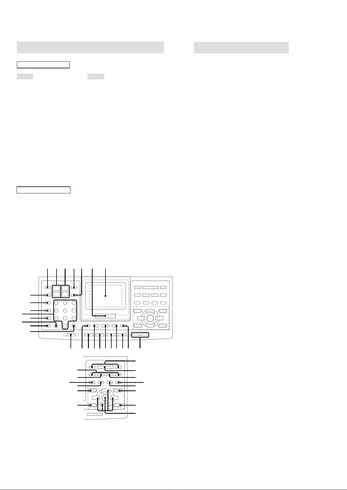
Location of Controls ....................................................... 5
Setting the Clock............................................................. 6
3. DISASSEMBLY
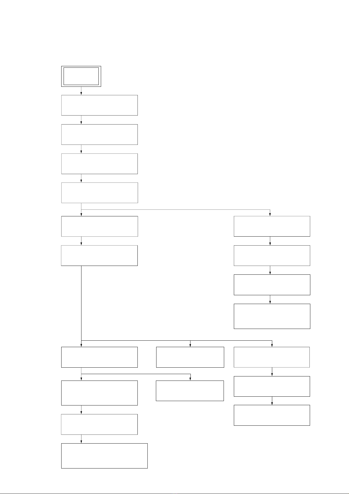
3-1. Disassembly Flow ........................................................... 7
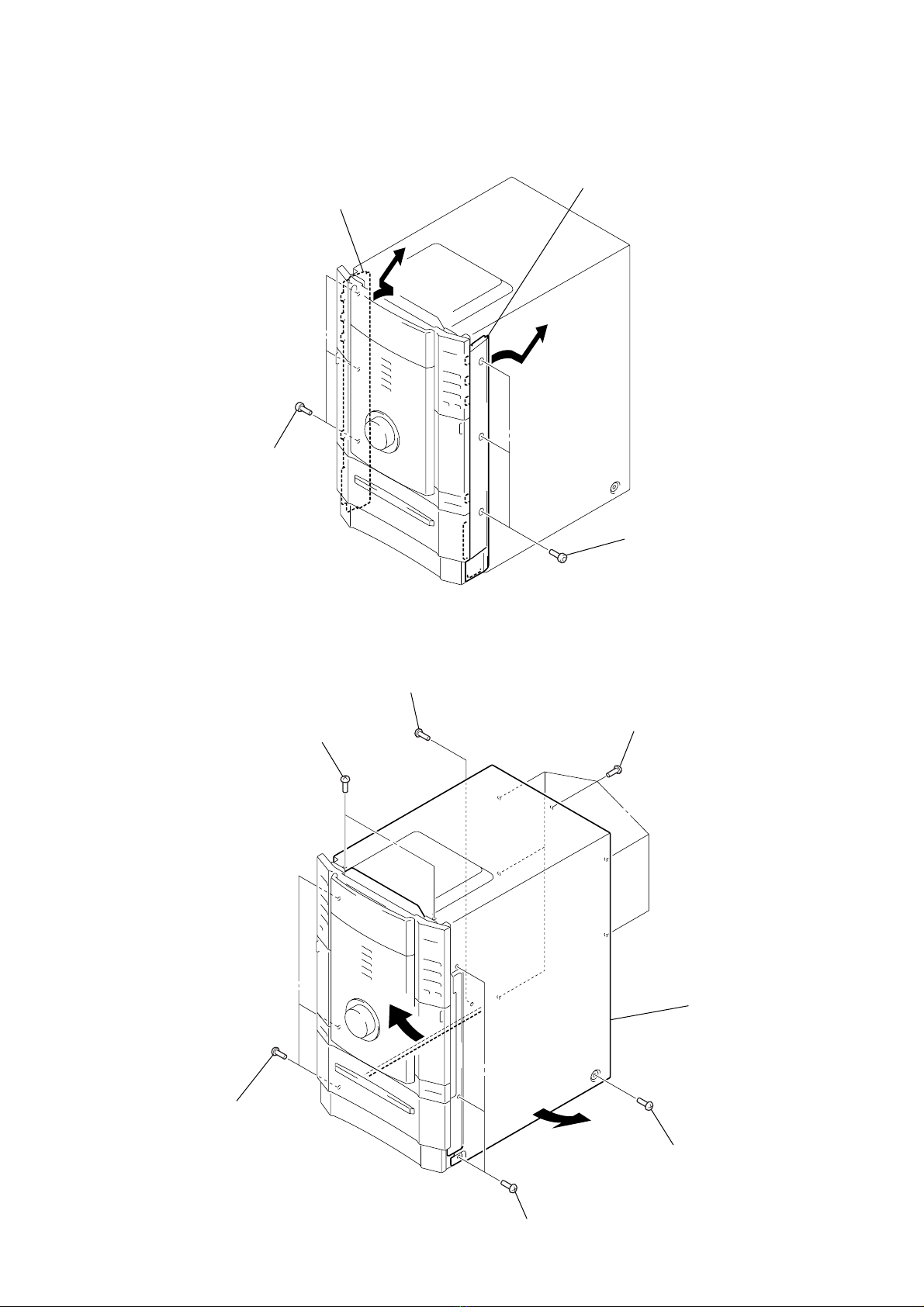
3-2. Top Panel Assy ................................................................ 8
3-3. Back Cover ...................................................................... 8
3-4. Side Panel (A)/(B)........................................................... 9
3-5. Case ................................................................................. 9
3-6. Front Panel Assy ............................................................. 10
3-7. GC Board......................................................................... 10
3-8. Tape Mechanism assy ..................................................... 11
3-9. Belt .................................................................................. 11
3-10. SW Board, HEAD (A) Board, HEAD (B) Board .......... 12
3-11. CD Mechanism Block..................................................... 12
3-12. CD Mechanism Deck (CDM53M-30BD60) .................. 13
3-13. Fitting Base Assy, Bracket (Chassis), Magnet Assy ...... 13
3-14. Base Unit (BU-30BD60) ................................................ 14
3-15. Tray (Sub)........................................................................ 14
3-16. Chassis (Mold B) Section, Stocker Section,
Slider (Selection) ............................................................ 15
3-17. SUB TRANS Board ........................................................ 15
3-18. Back Cover Section......................................................... 16
3-19. TRANS Board ................................................................. 16
3-20. SP RELAY Board............................................................ 17
4. ASSEMBLY
4-1. Assembly Flow................................................................ 18
4-2. Gears Installation ............................................................ 18
4-3. Slider (Selection) Installation ......................................... 19
4-4. Stocker Section Installation ............................................ 19
4-5. Chassis (Mold B) Section Installation............................ 20
5. TEST MODE.............................................................. 21
6. MECHANICAL ADJUSTMENTS....................... 25
7. ELECTRICAL ADJUSTMENTS......................... 25
Deck Section ................................................................... 25
CD Section ...................................................................... 28
8. DIAGRAMS
8-1. Block Diagram – CD SERVO Section – ....................... 30
8-2. Block Diagram – TUNER/TAPE DECK Section – ...... 31
8-3. Block Diagram – AUDIO DSP Section –...................... 32
8-4. Block Diagram – POWER AMP Section – ................... 33
8-5. Block Diagram
– DISPLAY/POWER SUPPLY Section – ...................... 34
8-6. Note for Printed Wiring Boards and
Schematic Diagrams ....................................................... 35
8-7. Printed Wiring Board – BD Board – ............................. 36
8-8. Schematic Diagram – BD Board – ................................ 37
8-9. Printed Wiring Boards – CHANGER Section –............ 38
8-10. Schematic Diagram – CHANGER Section – ................ 39
8-11. Printed Wiring Boards – CD DOOR Section – ............. 40
8-12. Schematic Diagram – CD DOOR Section – ................. 41
8-13. Printed Wiring Board – SW Board – ............................. 42
8-14. Schematic Diagram – SW Board –................................ 43
8-15. Printed Wiring Boards – TC DOOR Section – ............. 44
8-16. Schematic Diagram – TC DOOR Section – .................. 45
8-17. Printed Wiring Board – MC Board –............................. 46
8-18. Schematic Diagram – MC Board – ............................... 47
8-19. Printed Wiring Board
– DSP Board (Component Side) –.................................. 48
8-20. Printed Wiring Board
– DSP Board (Conductor Side) – ................................... 49
8-21. Schematic Diagram – DSP Board (1/3) – ..................... 50
8-22. Schematic Diagram – DSP Board (2/3) – ..................... 51
8-23. Schematic Diagram – DSP Board (3/3) – ..................... 52
8-24. Printed Wiring Board
– FRONT REAR AMP Board –...................................... 54
8-25. Schematic Diagram
– FRONT REAR AMP Board –...................................... 55
8-26. Printed Wiring Board
– CENTER SW AMP Board –........................................ 56
8-27. Schematic Diagram
– CENTER SW AMP Board –........................................ 57
8-28. Printed Wiring Boards – SPEAKER Section – ............. 58
8-29. Schematic Diagram – REGULATOR Board –.............. 59
8-30. Schematic Diagram – SPEAKER Section (1/2) –......... 60
8-31. Schematic Diagram – SPEAKER Section (2/2) –......... 61
8-32. Printed Wiring Board – GC Board – ............................. 62
8-33. Schematic Diagram – GC Board – ................................ 63
8-34. Printed Wiring Boards – PANEL Section – .................. 64
8-35. Schematic Diagram – PANEL Section – ....................... 65
8-36. Printed Wiring Board – MIC Board – ........................... 66
8-37. Schematic Diagram – MIC Board – .............................. 67
8-38. Printed Wiring Board – SUB TRANS Board –............. 68
8-39. Schematic Diagram – SUB TRANS Board –................ 69
8-40. Printed Wiring Board – TRANS Board –...................... 70
8-41. Schematic Diagram – TRANS Board –......................... 71
8-42. IC Pin Function Description ........................................... 75
9. EXPLODED VIEWS
9-1. Case Section .................................................................... 83
9-2. Front Panel Section-1...................................................... 84
9-3. Front Panel Section-2...................................................... 85
9-4. Front Panel Section-3...................................................... 86
9-5. Front Panel Section-4...................................................... 87
9-6. Chassis Section-1 ............................................................ 88
9-7. Chassis Section-2 ............................................................ 89
9-8. Chassis Section-3 ............................................................ 90
9-9. Chassis Section-4 ............................................................ 91
9-10. CD Mechanism Deck Section-1
(CDM53M-30BD60) ...................................................... 92
9-11. CD Mechanism Deck Section-2
(CDM53M-30BD60) ...................................................... 93
9-12. CD Mechanism Deck Section-3
(CDM53M-30BD60) ...................................................... 94
9-13. CD Mechanism Deck Section-4
(CDM53M-30BD60) ...................................................... 95
9-14. Base Unit Section (BU-30BD60) ................................... 96
9-15. Tape Mechanism Deck Section
(TCM-230AWR41CS) .................................................... 97
10. ELECTRICAL PARTS LIST ............................... 98

4
HCD-FL3
NOTES ON HANDLING THE OPTICAL PICK-UP
BLOCK OR BASE UNIT
The laser diode in the optical pick-up block may suffer electro-
static break-down because of the potential difference generated
by the charged electrostatic load, etc. on clothing and the human
body.
During repair, pay attention to electrostatic break-down and also
use the procedure in the printed matter which is included in the
repair parts.
The flexible board is easily damaged and should be handled with
care.
NOTES ON LASER DIODE EMISSION CHECK
The laser beam on this model is concentrated so as to be focused
on the disc reflective surface by the objective lens in the optical
pick-up block. Therefore, when checking the laser diode emis-
sion, observe from more than 30 cm away from the objective lens.
LASER DIODE AND FOCUS SEARCH OPERATION
CHECK
Carry out the “S curve check” in “CD section adjustment” and
check that the S curve waveforms is output three times.
•RELEASING THE DISC TRAY LOCK
The disc tray lock function for the antitheft of an demonstration
disc in the store is equipped.
Releasing Procedure :
Press two buttons of Z(CD) and [GROOVE] simultaneously for
five seconds. The message “UNLOCKED” is displayed and the
tray is unlocked.
Note: When “LOCKED” is displayed, the tray lock is not released by
turning power on/off with the [I/ ] button.
SERVICE POSITION
In checking the DSP/MC board, prepare jig (extension cable J-
2501-208-A: 1.25 mm Pitch, 21 cores, Length 370 mm).
SECTION 1
SERVICING NOTES
•MODEL IDENTIFICATION
– Back Panel –
MODEL PART No.
Singapore model 4-239-008-0[]
120 V AC area in E model 4-239-008-2[]
Mexican model 4-239-008-3[]
Chilean and Peruvian models 4-239-008-4[]
Argentina model 4-239-008-5[]
Australian model 4-239-008-6[]
PART No.
Connect jig (extension cable J-2501-208-A)
to the MC board (CN106) and BD board (CN101).
MC board (CN106) MC board
DSP board
Any board to put
BD board (CN101)
1
Ver 1.2

5
HCD-FL3
SECTION 2
GENERAL This section is extracted from
instruction manual.
LOCATION OF CONTROLS
– Front Panel –
ALPHABETICAL ORDER
A – G
CD es
CD SYNC HI-DUB qd
DIGITAL wd
DISC SELECT 4
DISC 1 indicator wk
DISC 2 indicator wj
DISC 3 indicator wh
DISC 4 indicator wg
DISC 5 indicator wf
Display window 2
DISPLAY wa
EFFECT qs
GROOVE qa
M – V
MD (VIDEO) ws
MIC jack ql
MIC LEVEL w;
MULTI CHANNEL DECODING
indicator 3
PHONES jack qh
REC PAUSE/START qf
Remote sensor wl
TAPE A/B e;
TUNER/BAND ea
VOLUME qg
BUTTON DESCRIPTIONS
?/1 (power) 1
Z(disc tray) 5
ZA (deck A) qk
ZB (deck B) qj
hH (play) 6
X(pause) 8
x(stop) 7
./>(go back/go forward)
9
–/m, M/+
(rewind, fast forward) q;
Z
ZZ
xX
>.
M+– m
hH
?/1
1
6
8
452 3
es
ea
e;
wd
ws
wa
w;
ql
qk
qa
qs
qd
qf
qg
qh
qj
7
9
q;
wk
wj
wh
wg
wf
wl
AOPTICAL DIGITAL IN jack
Use a digital optical cable (square, not
supplied) to connect an MD deck or DVD
player to this jack. You can then record or
listen to digital audio from the MD deck or
DVD player through this system.
BOPTICAL CD DIGITAL OUT jack
Use a digital optical cable (square, not
supplied) to connect an MD deck to this jack.
You can then output the digital audio to the
MD deck from this system.
CMD (VIDEO) IN jacks
Use audio cords (not supplied) to connect an
MD deck or VCR to these jacks. You can then
listen to analog audio from the MD deck or
VCR through this system.
DMD (VIDEO) OUT jacks
Use audio cords (not supplied) to connect an
MD deck or VCR to these jacks. You can then
output audio to the MD deck or VCR from this
system.
Tip
When you remove the optical cover, keep it for future
use.
– Back Panel –

6
HCD-FL3
ALPHABETICAL ORDER
A – K
2.1CH/MULTI e;
AMP MENU 9
CD qh
CLEAR ql
CLOCK/TIMER SELECT qj
CLOCK/TIMER SET qg
D.SKIP 5
digipad 7
DISPLAY 4
DSP EDIT qa
EDIT/TUNER MEMORY w;
EFFECT ej
ENTER 6
FUNCTION 0
GAME MODE eg
GROOVE qd
KARAOKE PON ek
M – V
MOVIE MODE es
MUSIC MODE eh
Numeric buttons wd
P FILE ea
PLAY MODE/DIRECTION ws
PRESET +/– wj
REPEAT/FM MODE wf
SLEEP wg
TAPE A/B qs
TOOL MODE ed
TUNER/BAND qf
TUNING +/– r;
TV/VIDEO wh
TV ?/1 1
TV CH +/– 3
TV VOL +/– 2
VOLUME +/– 8
BUTTON DESCRIPTIONS
?/1 (power) qk
hH (play) wk
X(pause) el
x(stop) wl
.(go back) wj
>(go forward) wj
m(rewind) r;
M
(fast forward)r;
V/v/B/b/ENTER ef
>10 wa
Bb
v
V
Bb
v
V
1 2 3 45 6 7
890qaqsqdqfqgqhqjqk
ql
wh
wk
wj
wl e;
ea
es
ed
ef
eg
eh
ej
ek
el
r;
wg
wf
ws
w;
wa
wd
Remote Control
Setting the clock
1Turn on the system.
2Press CLOCK/TIMER SET on the
remote.
3Press .or >repeatedly to set the
hour.
4Press ENTER on the remote.
5Press .or >repeatedly to set the
minutes.
6Press ENTER on the remote.
To adjust the clock
1Press CLOCK/TIMER SET on the remote.
2Press .or >repeatedly to select
CLOCK SET?, then press ENTER on the
remote.
3Do the same procedures as step 3 to 6
above.
Note
The clock settings are canceled when you disconnect
the power cord or if a power failure occurs.

7
HCD-FL3
• This set can be disassembled in the order shown below.
3-1. DISASSEMBLY FLOW
SECTION 3
DISASSEMBLY
3-4. SIDE PANEL (A)/(B)
(Page 9)
3-3. BACK COVER
(Page 8)
3-2. TOP PANEL ASSY
(Page 8)
3-5. CASE
(Page 9)
3-7. GC BOARD
(Page 10)
3-13. FITTING BASE ASSY,
BRACKET (CHASSIS),
MAGNET ASSY
(Page 13)
3-16. CHASSIS (MOLD B) SECTION,
STOCKER SECTION,
SLIDER (SELECTION)
(Page 15)
3-11. CD MECHANISM BLOCK
(Page 12)
3-15. TRAY (SUB)
(Page 14)
3-12. CD MECHANISM DECK
(CDM53M-30BD60)
(Page 13)
3-19. TRANS BOARD
(Page 16)
3-20. SP RELAY BOARD
(Page 17)
3-17. SUB TRANS BOARD
(Page 15) 3-18. BACK COVER SECTION
(Page 16)
3-14. BASE UNIT
(BU-30BD60)
(Page 14)
3-6. FRONT PANEL ASSY
(Page 10)
3-8. TAPE MECHANISM ASSY
(Page 11)
3-9. BELT
(Page 11)
3-10. SW BOARD,
HEAD (A) BOARD,
HEAD (B) BOARD
(Page 12)
SET

8
HCD-FL3
Note: Follow the disassembly procedure in the numerical order given.
3-2. TOP PANEL ASSY
3-3. BACK COVER
1
four screws
(hexagon socket tapping)
2
top panel ass
y
1
five screws
(BVTP3
×
8)
2
back cover

9
HCD-FL3
3-4. SIDE PANEL (A) / (B)
3-5. CASE
4
side panel (A)
1
three screws
(top)
2
side panel (B)
3
three screws
(top)
5
two screws
(BVTP3
×
8)
2
six screws
(BVTT3
×
8 (S))
1
three screws
(BVTP3
×
8)
1
three screws
(BVTP3
×
8)
6
6
4
screw (case 3 TP2
)
7
case
3
screw (case 3 TP2)

10
HCD-FL3
3-6. FRONT PANEL ASSY
3-7. GC BOARD
two claws
qg
Rifting up the CD mechanism block
section, and release two claws.
7
connector
(CN1)
8
connector
(CN808)
9
connector
(CN318)
1
wire (flat type) (15 core)
(CN206)
5
wire (flat type)
(17 core) (CN109)
2
connector
(CN201)
3
connector
(CN203)
4
connector
(CN207)
6
connector
(CN2)
qf
two screws
(BVTP3
×
8)
0
screw
(BVTP3
×
8)
qs
screw
(BVTP3
×
8)
qa
harness
qd
harness
qh
front panel assy
4
three screws
(BVTP3
×
8)
2
wire (flat type) (19 core)
(CN202)
1
wire (flat type) (17 core)
(CN204)
3
connector
(CN713)
5
GC board

11
HCD-FL3
3-8. TAPE MECHANISM ASSY
3-9. BELT
1
two screws
(2.6
×
8)
5
tape mechanism ass
y
2
two screws
3
Push two solenoids.
4
Open cassette lid.
1
two
screws
(PS 2.6
×
5)
2
motor assy
(capstan
)
(M901)
3
belt
(capstan C)
4
belt
(capstan B)
4
belt
(capstan B)
5
belt
(FR)
5
belt
(FR)

12
HCD-FL3
3-10. SW BOARD, HEAD (A) BOARD AND HEAD (B) BOARD
3-11. CD MECHANISM BLOCK
6
screw (PTT 2
×
4)
4
screw (PTT 2
×
4)
3
SW board
2
five claws
5
head (A) board
7
head (B) board
1
Remove the four solders.
5
two connector
(CN805, 806)
6
CD mechanism block
2
connector
(CN903)
1
wire (flat type) (11 core)
(CN105)
3
connector
(CN807)
4
five screws
(BVTP3
×
8
)

13
HCD-FL3
1
two connectors
(CN709, 715)
7
connecto
r
(CN710)
9
magnet assy
2
four screws
(BTTP M2.6)
8
four screws
(BTTP M2.6)
4
two screws
(BTTP M2.6)
6
Bracket
(chassis)
5
two screws
(BTTP M2.6)
3
fitting base
(guide) assy
3-13. FITTING BASE ASSY, BRACKET (CHASSIS), MAGNET ASSY
1
two screws
(BVTP 3
×
8)
1
two screws
(BVTP 3
×
8)
2
bracket top panel
4
chassis (CDM)
3
four screws
(BVTP 3
×
8)
5
CD mechanism deck
(CDM53M-30BD60)
3-12. CD MECHANISM DECK (CDM53M-30BD60)

14
HCD-FL3
3-14. BASE UNIT (BU-30BD60)
3-15. TRAY (SUB)
5
base unit
(BU-30BD60)
4
two screws
(PTPWH M2.6
)
1
connector
(CN710)
3
magnet assy
2
four screws
(BTTP M2.6)
A
B
pully (LD)
stocker section
tray (sub)
slider (selection)
pully (mode)
1
Rotating the pulley (LD), shift the slider (selection) in the arrow
A
direction.
2
Rotating the pulley (mode) in the arrow direction, adjust the tray (sub) to be removed.
3
Rotating the pulley (LD), shift the slider (selection) in the arrow
B
direction.
4
Rotating the pulley (mode) in the arrow direction, remove the tray (sub) to be removed.

15
HCD-FL3
3-17. SUB TRANS BOARD
3-16. CHASSIS (MOLD B) SECTION, STOCKER SECTION, SLIDER (SELECTION)
5
stocker
section
1
three screws
(BVTP M2.6)
2
chassis (mold B) section
3
gear (eject)
4
two step screws
4
two step
screws
6
two screws
(PTPWH M2.6)
7
slider (selection)
8
washer
9
compression
spring
Pully (LD)
Note: Rotating the pully (LD),
shift the slider (selection)
to the left.
3
three screw
s
(BVTP3
×
8)
2
connector
(CN902)
1
connector
(CN901)
4
SUB TRANS board

16
HCD-FL3
3-18. BACK COVER SECTION
3-19. TRANS BOARD
4
two screws
(BVTP3
×
8)
5
screw (BVTP3
×
8
)
1
connector
(CN902)
3
connector
(CN901)
2
connector
(CN809)
6
back cover section
5
TRANS board
4
four screws
3
connector (CN915)
1
connector (CN914)
2
connector (CN916)

17
HCD-FL3
3-20. SP RELAY BOARD
2
screw (BVTP3
×
8)
5
screw claws
1
two screws
(BVTP3
×
8)
4
three connectors
(CN801, 803, 804)
6
SP relay board
front rear AMP board
center SW AMP board
3
chassis

HCD-FL3
18
• This set can be assembled in the order shown below.
4-1. ASSEMBLY FLOW
SECTION 4
ASSEMBLY
GEARS INSTALLATION
(Page 18)
SLIDER (SELECTION) INSTALLATION
(Page 19)
STOCKER SECTION INSTALLATION
(Page 19)
CHASSIS (MOLD B) SECTION
INSTALLATION (Page 20)
1
Slide the slider (u/d)
fully in the arrow
direction.
3
gear (gear B)
2
gear (U/D slider)
4
gear (gear A)
portion A
Adjust the gear (gear B) with the
portion A as shown.
slider (U/D) gear
Adjust the gear so that it meshes with
the bottom tooth of slider (U/D) gear,
as shown.
gear
(gear B) linearly
Adjust so as to be aligned with
gear B linearly, as shown.
4-2. GEARS INSTALLATION
Note: Follow the assembly procedure in the numerical order given.

HCD-FL3
19
2
portion A of tray (sub)
1
stocker section
3
two step screws
3
two step screws
Hook the portion A of tray (sub)
to the slider (selection).
portion A
of tray (sub) sticking of
slider (selection)
2
gear (chuking)
6
two screws
(PTPWH M2.6)
5
washer
3
convex portion of
slider (selection)
4
compression spring
7
Insert the slider (selection)
into the portion A.
1
rotary encoder
rotary encoder
Align with the slot of
rotary encoder.
align marking
portion A
Gear (chuking)
Insert a convex portion into
a groove of gear (chuking).
4-3. SLIDER (SELECTION) INSTALLATION
4-4. STOCKER SECTION INSTALLATION

HCD-FL3
20
3
three screws
(BVTP M2.6)
2
Insert the gear (eject)
under the gear (LD
deceleration).
1
Insert the portion A of
chassis (mold B) section
into the portion B of
slider (selection).
gear (LD deceleration)
portion A
portion B of
slider (selection)
4-5. CHASSIS (MOLD B) SECTION INSTALLATION
Table of contents
Other Sony Stereo System manuals

Sony
Sony SRS-XB3 User manual

Sony
Sony ZS-D55 User manual

Sony
Sony HCD-EP315 User manual

Sony
Sony Muteki XROSSFADE LBT-DJ2i User manual

Sony
Sony LBT-D550 User manual

Sony
Sony RDP-X200iPN User manual

Sony
Sony HCD-DR3 User manual

Sony
Sony MHC-V77DW User manual

Sony
Sony ICF-C11iP User manual

Sony
Sony CMT-EX5 - Micro Hi Fi Component System User manual

Sony
Sony HCD-GS100 - Mini Hi-fi Component System User manual

Sony
Sony GTK-X1BT User manual

Sony
Sony HCD-CPZ1 User manual

Sony
Sony HCD-R500 User manual

Sony
Sony LBT-N350 User manual

Sony
Sony Giga Juke NAS-SC55PKE User manual

Sony
Sony HCD-EP515 User manual

Sony
Sony CMT-CP555 User manual

Sony
Sony HCD-RG222 User manual

Sony
Sony FST-ZUX999 User manual