Sony HCD-GPX9 User manual

SERVICE MANUAL
COMPACT DISC DECK RECEIVER
AEP Model
UK Model
HCD-GPX9
Ver. 1.1 2005.05
SPECIFICATIONS
9-879-468-02
2005E05-1
© 2005.05
Sony Corporation
Personal Audio Group
Published by Sony Engineering Corporation
– Continued on next page –
HCD-GPX9 is the amplifier, CD player, tape deck
and tuner section in CMT-GPX9DAB.
Model Name Using Similar Mechanism HCD-GPX5
CD CD Mechanism Type CDM80B-K6BD80A
Section Base Unit Name BU-K6BD80A
Optical Pick-up Block Name KSM-213DCP
Tape deck Model Name Using Similar Mechanism HCD-GPX5
Section Tape Transport Mechanism Type CMAL1Z234A
AUDIO POWER SPECIFICATIONS
Main unit
Amplifier section
DIN power output (rated): 30 + 30 W
(6 ohms at 1 kHz, DIN)
Continuous RMS power output (reference):
35 + 35 W
(6 ohms at 1 kHz, 10%
THD)
Music power output (reference):
60 + 60 W
Inputs
AUDIO IN: Sensitivity 250 mV,
impedance 47 kilohms
Outputs
PHONES: Accepts headphones with
an impedance of 8 ohms or
more
SPEAKER: Accepts impedance of 6 to
16 ohms.
CD player section
Laser Diode Properties Emission Duration:
Continuous
Laser Output*:
Less than 44.6 µW
µ
*This output is the value measurement at a distance of
200 mm from the objective lens surface on the
Optical Pick-up Block with 7 mm operture.
Frequency response 20 Hz – 20 kHz
Wavelength 780 – 790 nm
Aerial terminal 75 Ω, F female
FM stereo, FM/AM superheterodyne tuner
FM tuner section
Tuning range 87.5 – 108.0 MHz
Aerial FM lead aerial
Aerial terminals 75 ohms unbalanced
Intermediate frequency 10.7 MHz
AM tuner section
Tuning range 531 – 1,602 kHz
(with the tuning interval
set at 9 kHz)
Aerial AM loop aerial, external
aerial terminal
Intermediate frequency 450 kHz
Tape deck section
Recording system 4-track 2-channel, stereo
Frequency response 50 – 13,000 Hz (±3 dB),
using Sony TYPE I
cassettes
Tuner section
DAB tuner section
Frequency range
Band-III: 174.928 (5A) –
239.200 (13F) MHz
L-Band: 1452.960 MHz (L1) –
1490.624 MHz (L23)
(L-Band is not available
for the UK model.)
*For details, see “DAB frequency table” below.
w
w
w
.
x
i
a
o
y
u
1
6
3
.
c
o
m
Q
Q
3
7
6
3
1
5
1
5
0
9
9
2
8
9
4
2
9
8
T
E
L
1
3
9
4
2
2
9
6
5
1
3
9
9
2
8
9
4
2
9
8
0
5
1
5
1
3
6
7
3
Q
Q
TEL 13942296513 QQ 376315150 892498299
http://www.xiaoyu163.com

2
HCD-GPX9
Notes on chip component replacement
•Never reuse a disconnected chip component.
•Notice that the minus side of a tantalum capacitor may be
damaged by heat.r may be damaged by heat.
Flexible Circuit Board Repairing
•Keep the temperature of the soldering iron around 270 ∞C
during repairing.
•Do not touch the soldering iron on the same conductor of the
circuit board (within 3 times).
•Be careful not to apply force on the conductor when soldering
or unsoldering.
This appliance is classified as
a CLASS 1 LASER product.
The CLASS 1 LASER
PRODUCT MARKING is
located on the rear exterior.
CAUTION
Use of controls or adjustments or performance of procedures
otherthanthosespecified herein may result inhazardousradiation
exposure.
SAFETY-RELATED COMPONENT WARNING!!
COMPONENTS IDENTIFIED BY MARK 0OR DOTTED LINE
WITH MARK 0ON THE SCHEMATIC DIAGRAMS AND IN
THE PARTS LIST ARE CRITICAL TO SAFE OPERATION.
REPLACE THESE COMPONENTS WITH SONY PARTS WHOSE
PART NUMBERS APPEAR AS SHOWN IN THIS MANUAL OR
IN SUPPLEMENTS PUBLISHED BY SONY.
L-Band
Notes
•L-Band is not available for the UK model.
•Frequencies are displayed to two places of decimals
on this system.
Frequency Label
1452.960 MHz L1
1454.672 MHz L2
1456.384 MHz L3
1458.096 MHz L4
1459.808 MHz L5
1461.520 MHz L6
1463.232 MHz L7
1464.944 MHz L8
1466.656 MHz L9
1468.368 MHz L10
1470.080 MHz L11
1471.792 MHz L12
1473.504 MHz L13
1475.216 MHz L14
1476.928 MHz L15
1478.640 MHz L16
1480.352 MHz L17
1482.064 MHz L18
1483.776 MHz L19
1485.488 MHz L20
1487.200 MHz L21
1488.912 MHz L22
1490.624 MHz L23
Power consumption 85 W
0.25 W (in Power Saving
Mode)
Dimensions (w/h/d) Approx. 181.5 × 261.5 ×
357.5 mm incl. projecting
parts and controls
Mass Approx. 5.8 kg
General
Power requirements 230 V AC, 50/60 Hz
Design and specifications are subject to change
without notice.
DAB frequency table
Band-III
Note
Frequencies are displayed to two places of decimals on
this system.
Frequency Label Frequency Label
174.928 MHz 5A 209.936 MHz 10A
176.640 MHz 5B 211.648 MHz 10B
178.352 MHz 5C 213.360 MHz 10C
180.064 MHz 5D 215.072 MHz 10D
181.936 MHz 6A 216.928 MHz 11A
183.648 MHz 6B 218.640 MHz 11B
185.360 MHz 6C 220.352 MHz 11C
187.072 MHz 6D 222.064 MHz 11D
188.928 MHz 7A 223.936 MHz 12A
190.640 MHz 7B 225.648 MHz 12B
192.352 MHz 7C 227.360 MHz 12C
194.064 MHz 7D 229.072 MHz 12D
195.936 MHz 8A 230.784 MHz 13A
197.648 MHz 8B 232.496 MHz 13B
199.360 MHz 8C 234.208 MHz 13C
201.072 MHz 8D 235.776 MHz 13D
202.928 MHz 9A 237.488 MHz 13E
204.640 MHz 9B 239.200 MHz 13F
206.352 MHz 9C
208.064 MHz 9D
w
w
w
.
x
i
a
o
y
u
1
6
3
.
c
o
m
Q
Q
3
7
6
3
1
5
1
5
0
9
9
2
8
9
4
2
9
8
T
E
L
1
3
9
4
2
2
9
6
5
1
3
9
9
2
8
9
4
2
9
8
0
5
1
5
1
3
6
7
3
Q
Q
TEL 13942296513 QQ 376315150 892498299
http://www.xiaoyu163.com

3
HCD-GPX9
TABLE OF CONTENTS
1. SERVICING NOTES ............................................... 4
2. GENERAL
Location of Controls........................................................ 6
3. DISASSEMBLY
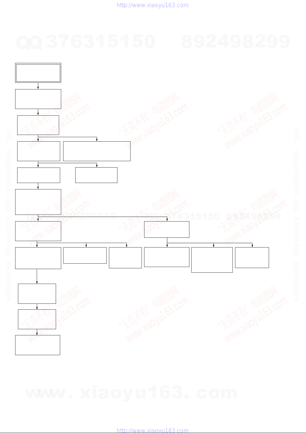
3-1. Disassembly Flow ........................................................... 8
3-2. Side Plate (L)/(R) ............................................................ 9
3-3. Top Block Assy ............................................................... 9
3-4. Tape Mechanism Deck (CMAL1Z234A)........................ 10
3-5. Front Panel Section ......................................................... 10
3-6. MAIN Board.................................................................... 11
3-7. DAB Board ...................................................................... 11
3-8. CD Mechanism Deck Block............................................ 12
3-9. Base Unit (BU-K6BD80A) ............................................. 12
3-10. BD Board......................................................................... 13
3-11. Driver Board .................................................................... 13
3-12. Chassis (Top) ................................................................... 14
3-13. Lever (Loading-L/R) ....................................................... 15
3-14. Lever (Disc Sensor)/(Disc Stop) ..................................... 16
3-15. Holder (BU215) Assy ...................................................... 16
3-16. Lever (BU Lock) ............................................................. 17
3-17. Close Lever...................................................................... 17
3-18. Lever (Dir), Gear (IDL-B)............................................... 18
3-19. Gear (IDL-C) ................................................................... 18
4. TEST MODE.............................................................. 19
5. ELECTRICAL ADJUSTMENTS
Deck Section.................................................................... 21
CD Section ...................................................................... 22
6. DIAGRAMS
6-1. Block Diagram – CD SERVO Section – ........................ 23
6-2. Block Diagram – AUDIO Section – ............................... 24
6-3. Block Diagram
– PANEL/POWER SUPPLY Section – ........................... 25
6-4. Printed Wiring Board – DRIVER Board – ..................... 27
6-5. Schematic Diagram – DRIVER Board –........................ 27
6-6. Printed Wiring Board – BD Board – .............................. 28
6-7. Schematic Diagram – BD Board – ................................. 29
6-8. Printed Wiring Board – DAB Board –............................ 30
6-9. Schematic Diagram – DAB Board – .............................. 31
6-10. Printed Wiring Board – MAIN Board – ......................... 32
6-11. Schematic Diagram – MAIN Board (1/3) – ................... 33
6-12. Schematic Diagram – MAIN Board (2/3) – ................... 34
6-13. Schematic Diagram – MAIN Board (3/3) – ................... 35
6-14. Printed Wiring Board – AMP Board – ........................... 36
6-15. Schematic Diagram – AMP Board – .............................. 37
6-16. Printed Wiring Board – PANEL (1) Board –.................. 38
6-17. Schematic Diagram – PANEL (1) Board – .................... 39
6-18. Printed Wiring Board – PANEL (2) Board –.................. 40
6-19. Schematic Diagram – PANEL (2) Board – .................... 41
6-20. Printed Wiring Board – POWER Board – ...................... 42
6-21. Schematic Diagram – POWER Board –......................... 43
7. EXPLODED VIEWS
7-1. Side Plates Section .......................................................... 52
7-2. Front Panel Section ......................................................... 53
7-3. Top Block Section ........................................................... 54
7-4. MAIN Section ................................................................. 55
7-5. Chassis Section-2 ............................................................ 56
7-6. CD Mechanism Deck Section-1
(CDM80B-K6BD80A) .................................................... 57
7-7. CD Mechanism Deck Section-2
(CDM80B-K6BD80A) .................................................... 58
7-8. CD Mechanism Deck Section-3
(CDM80B-K6BD80A) .................................................... 59
7-9. CD Mechanism Deck Section-4
(CDM80B-K6BD80A) .................................................... 60
7-10. Base Unit Section (BU-K6BD80A) ................................ 61
8. ELECTRICAL PARTS LIST................................ 62
w
w
w
.
x
i
a
o
y
u
1
6
3
.
c
o
m
Q
Q
3
7
6
3
1
5
1
5
0
9
9
2
8
9
4
2
9
8
T
E
L
1
3
9
4
2
2
9
6
5
1
3
9
9
2
8
9
4
2
9
8
0
5
1
5
1
3
6
7
3
Q
Q
TEL 13942296513 QQ 376315150 892498299
http://www.xiaoyu163.com

4
HCD-GPX9
The laser diode in the optical pick-up block may suffer electrostatic
break-down because of the potential difference generated by the
charged electrostatic load, etc. on clothing and the human body.
During repair, pay attention to electrostatic break-down and also
use the procedure in the printed matter which is included in the
repair parts.
The flexible board is easily damaged and should be handled with
care.
NOTES ON LASER DIODE EMISSION CHECK
The laser beam on this model is concentrated so as to be focused on
the disc reflective surface by the objective lens in the optical pick-
up block. Therefore, when checking the laser diode emission,
observe from more than 30 cm away from the objective lens.
LASER DIODE AND FOCUS SEARCH OPERATION
CHECK
Carry out the“S curve check” in“CD section adjustment” and check
that the S curve waveforms is output three times.
NOTES ON HANDLING THE OPTICAL PICK-UP
BLOCK OR BASE UNIT
SERVICE POSITION
–Tape Mechanism Deck –
SECTION 1
SERVICING NOTES
tape mechanism deck
UNLEADED SOLDER
Boards requiring use of unleaded solder are printed with the lead-
free mark (LF) indicating the solder contains no lead.
(Caution: Some printed circuit boards may not come printed with
the lead free mark due to their particular size)
: LEAD FREE MARK
Unleaded solder has the following characteristics.
•Unleaded solder melts at a temperature about 40 °C higher
than ordinary solder.
Ordinary soldering irons can be used but the iron tip has to be
applied to the solder joint for a slightly longer time.
Soldering irons using a temperature regulator should be set to
about 350 °C.
Caution: The printed pattern (copper foil) may peel away if
the heated tip is applied for too long, so be careful!
•Strong viscosity
Unleaded solder is more viscou-s (sticky, less prone to flow)
than ordinary solder so use caution not to let solder bridges
occur such as on IC pins, etc.
•Usable with ordinary solder
It is best to use only unleaded solder but unleaded solder may
also be added to ordinary solder.
w
w
w
.
x
i
a
o
y
u
1
6
3
.
c
o
m
Q
Q
3
7
6
3
1
5
1
5
0
9
9
2
8
9
4
2
9
8
T
E
L
1
3
9
4
2
2
9
6
5
1
3
9
9
2
8
9
4
2
9
8
0
5
1
5
1
3
6
7
3
Q
Q
TEL 13942296513 QQ 376315150 892498299
http://www.xiaoyu163.com

5
HCD-GPX9
– CD Mechanism deck –
– AMP Board –
2
Remove the AMP board
from heat sink.
AMP board
1
two screws
(BVTP3
×
16)
heat sink
heat sink
CD mechanism deck
w
w
w
.
x
i
a
o
y
u
1
6
3
.
c
o
m
Q
Q
3
7
6
3
1
5
1
5
0
9
9
2
8
9
4
2
9
8
T
E
L
1
3
9
4
2
2
9
6
5
1
3
9
9
2
8
9
4
2
9
8
0
5
1
5
1
3
6
7
3
Q
Q
TEL 13942296513 QQ 376315150 892498299
http://www.xiaoyu163.com

6
HCD-GPX9 SECTION 2
GENERAL This section is extracted from
instruction manual.
Main unit
BASS +/– wk
Cassette compartment 4
CD SYNCHRO 7
DAB qf
DIRECTION 6
Disc slot wf
DISPLAY ea
Display window 3
DSGX qs
FM MODE wh
FUNCTION e;
PHONES jack wd
PLAY MODE ws
Remote sensor 2
REPEAT wa
TREBLE +/– qd
TUNER/BAND qg
TUNING MODE wj
TUNING +/– wg
VOLUME qa
?/1 (power) 1
./> (CD skip back/skip
forward) w;
m/M (CD rewind/fast
forward) ql
m/M (tape rewind/fast
forward) wl
x(CD stop) qj
x(tape stop) 9
zREC PAUSE/START 8
CD/NX (play/pause) qk
TAPE/nN (play) 0
A(CD eject) qh
APUSH EJECT (tape open/close)
5
List of button locations and reference pages
ALPHABETICAL ORDER
A – O P – Z
BUTTON DESCRIPTIONS
?
/
1
mM
Y
x
mM
.>
N
Xx
Z
12 3 56
7
8
9
w
;
q
l
w
d
w
s
w
a
q
k
0
qs
qd
qf
qg
wf
wg
wh
wj
wk
wl
e;
ea
q
h
q
j
qa
4
w
w
w
.
x
i
a
o
y
u
1
6
3
.
c
o
m
Q
Q
3
7
6
3
1
5
1
5
0
9
9
2
8
9
4
2
9
8
T
E
L
1
3
9
4
2
2
9
6
5
1
3
9
9
2
8
9
4
2
9
8
0
5
1
5
1
3
6
7
3
Q
Q
TEL 13942296513 QQ 376315150 892498299
http://www.xiaoyu163.com

7
HCD-GPX9
Remote control
CD qh
CLEAR qd
CLOCK/TIMER SELECT 2
PLAY MODE qk
REPEAT 4
SLEEP w;
TAPE qg
TUNER BAND 5
TUNER MEMORY qj
TUNING MODE qk
VOLUME +/– qa
?/1 (power) 1
m/M (rewind/fast forward)
7
./> (skip back/skip
forward) qf
x(stop) 8
X(pause) 8
N(play) 8
+/– (tuning) qf
ALPHABETICAL ORDER
A – O P – Z
BUTTON DESCRIPTIONS
4
5
6
7
8
9
w; 1
qd
qs
ql
qk
qj
qh
qg
qf
qa
0
3
2
CLOCK/TIMER SET 3
DAB 6
DISPLAY ql
ENTER 9
EQ qs
FM MODE 4
FUNCTION q;
Use buttons on the remote for the operation.
1Press ?/1 to turn on the unit.
2Press CLOCK/TIMER SET.
3Press . or >repeatedly to set the
hour.
4Press ENTER.
5Press . or >repeatedly to set the
minute.
6Press ENTER.
The clock starts working.
To adjust the clock
1
Press CLOCK/TIMER SET.
2
Press . or >repeatedly to select
“CLOCK SET”, then press ENTER.
3
Do the same procedures as step 3 to 6
above.
Note
The clock is not displayed in Power Saving Mode.
Setting the clock
w
w
w
.
x
i
a
o
y
u
1
6
3
.
c
o
m
Q
Q
3
7
6
3
1
5
1
5
0
9
9
2
8
9
4
2
9
8
T
E
L
1
3
9
4
2
2
9
6
5
1
3
9
9
2
8
9
4
2
9
8
0
5
1
5
1
3
6
7
3
Q
Q
TEL 13942296513 QQ 376315150 892498299
http://www.xiaoyu163.com

HCD-GPX9
8
•This set can be disassembled in the order shown below.
3-1. DISASSEMBLY FLOW
SECTION 3
DISASSEMBLY
SET
3-2. SIDE PLATE
(L)/(R)
(Page 9)
3-8. CD
MECHANISM
DECK BLOCK
(Page 11)
3-15. HOLDER
(BU215) ASSY
(Page 15)
3-16. LEVER
(BU LOCK)
(Page 16)
3-17. CLOSE
LEVER
(Page 16)
3-18. LEVER (DIR),
GEAR (IDL-B)
(Page 17)
3-10. BD BOARD
(Page 12)
3-9. BASE UNIT
(BU-K6BD80A)
(Page 12)
3-12. CHASSIS (TOP)
(Page 13)
3-11. DRIVER
BOARD
(Page 13)
3-13. LEVER
(LOADING-L/R)
(Page 14)
3-14. LEVER (DISC
SENSOR)/
(DISC STOP )
(Page 15)
3-19. GEAR
(IDL-C)
(Page 17)
3-4. TAPE MECHANISM DECK
(CMAL1Z234A)
(Page 10)
3-7. DAB BOARD
(Page 10)
3-5. FRONT PANEL
SECTION
(Page 10)
3-6. MAIN BOARD
(Page 11)
3-3. TOP BLOCK
ASSY
(Page 9)
w
w
w
.
x
i
a
o
y
u
1
6
3
.
c
o
m
Q
Q
3
7
6
3
1
5
1
5
0
9
9
2
8
9
4
2
9
8
T
E
L
1
3
9
4
2
2
9
6
5
1
3
9
9
2
8
9
4
2
9
8
0
5
1
5
1
3
6
7
3
Q
Q
TEL 13942296513 QQ 376315150 892498299
http://www.xiaoyu163.com

HCD-GPX9
9
3-3. TOP BLOCK ASSY
Note: Follow the disassembly procedure in the numerical order given.
3-2. SIDE PLATE (L) / (R)
q;
side plate (R)
7
two screws
(BVTT3
×
6)
4
two screws
(BVTT3
×
8)
5
side plate (L)
1
screw
(BVTP3
×
10)
2
two screws
(BVTT3
×
6)
3
screw
(BVTP3
×
10)
6
screw
(BVTP3
×
10)
8
screw
(BVTP3
×
10)
9
two screws
(BVTT3
×
8)
5
8
top block assy
7
connector
(CN301)
2
screw
(BVTT3
×
6)
6
wire (flat type)
(7 core) (CN302)
4
Open the plate.
3
harness
4
Open the plate.
1
screw
(BVTT3
×
6)
w
w
w
.
x
i
a
o
y
u
1
6
3
.
c
o
m
Q
Q
3
7
6
3
1
5
1
5
0
9
9
2
8
9
4
2
9
8
T
E
L
1
3
9
4
2
2
9
6
5
1
3
9
9
2
8
9
4
2
9
8
0
5
1
5
1
3
6
7
3
Q
Q
TEL 13942296513 QQ 376315150 892498299
http://www.xiaoyu163.com

HCD-GPX9
10
3-4. TAPE MECHANISM DECK (CMAL1Z234A)
3-5. FRONT PANEL SECTION
2
harness
1
four screws
(BVTP3
×
8)
3
tape mechanism deck
(CMAL1Z234A)
5
front panel section
4
Open the plate.
3
two screws
(BVTT3
×
6)
1
wire (flat type)
(21 core) (CN310)
2
connector
(CN604)
4
Open the plate.
w
w
w
.
x
i
a
o
y
u
1
6
3
.
c
o
m
Q
Q
3
7
6
3
1
5
1
5
0
9
9
2
8
9
4
2
9
8
T
E
L
1
3
9
4
2
2
9
6
5
1
3
9
9
2
8
9
4
2
9
8
0
5
1
5
1
3
6
7
3
Q
Q
TEL 13942296513 QQ 376315150 892498299
http://www.xiaoyu163.com

HCD-GPX9
11
3-6. MAIN BOARD
3-7. DAB BOARD
qs
wire (flat type) (17 core)
(CN304)
1
wire (flat type) (9 core)
(CN306)
8
screw
(BVTT3
×
6)
qd
MAIN board
9
4
heat sink cover
7
three screw
s
(BVTP3
×
8)
3
two screws
(BVTT3
×
8)
2
three connectors
(CN603, 605, 901)
5
connector (CN201)
6
connector
(CN701)
0
wire (flat type)
(15 core) (CN305)
qa
wire (flat type)
(11 core) (CN315)
2
wire (flat type) (11 core)
(CN715)
1
connector
5
connector
(CN700)
7
module (DAB tuner)
6
two holders DAB
3
four screws
(BVTT3
×
6)
8
DAB board
4
w
w
w
.
x
i
a
o
y
u
1
6
3
.
c
o
m
Q
Q
3
7
6
3
1
5
1
5
0
9
9
2
8
9
4
2
9
8
T
E
L
1
3
9
4
2
2
9
6
5
1
3
9
9
2
8
9
4
2
9
8
0
5
1
5
1
3
6
7
3
Q
Q
TEL 13942296513 QQ 376315150 892498299
http://www.xiaoyu163.com

HCD-GPX9
12
3-9. BASE UNIT (BU-K6BD80A)
3-8. CD MECHANISM DECK BLOCK
qa
CD mechanism
deck block
5
screw
(BVTT3
×
6)
8
screw
(BVTT3
×
6)
9
two screws
(BVTT3
×
6)
0
cover (CDM)
3
screw
(BVTT3
×
6
)
7
1
connector
4
DAB block
6
three screws
(BVTT3
×
6)
2
two screws
(KTP3
×
8)
qs
base unit (BU-K6BD80A)
3
two screws
(BVTP3
×
10)
1
two screws
(BVTT3
×
10)
4
CD mecha bracket (R)
block
2
CD mecha bracket (L)
7
two coil springs
(insulator)
8
two insulators
6
two stoppers
(BU)
5
two screws
(BVTP M2.6)
9
two floating screws
(PTPWH M2.6)
0
two coil springs
(insulator)
qa
two insulators
w
w
w
.
x
i
a
o
y
u
1
6
3
.
c
o
m
Q
Q
3
7
6
3
1
5
1
5
0
9
9
2
8
9
4
2
9
8
T
E
L
1
3
9
4
2
2
9
6
5
1
3
9
9
2
8
9
4
2
9
8
0
5
1
5
1
3
6
7
3
Q
Q
TEL 13942296513 QQ 376315150 892498299
http://www.xiaoyu163.com

HCD-GPX9
13
3-10. BD BOARD
3-11. DRIVER BOARD
1
Remove four solders.
4
BD board
2
wire (flat type) (16 core)
(CN101)
3
screw (2.6)
3
Remove two solders.
2
two screws
(BVTP 2.6)
5
DRIVER board
4
motor (pully) assy
(loading)
1
belt (MOT)
w
w
w
.
x
i
a
o
y
u
1
6
3
.
c
o
m
Q
Q
3
7
6
3
1
5
1
5
0
9
9
2
8
9
4
2
9
8
T
E
L
1
3
9
4
2
2
9
6
5
1
3
9
9
2
8
9
4
2
9
8
0
5
1
5
1
3
6
7
3
Q
Q
TEL 13942296513 QQ 376315150 892498299
http://www.xiaoyu163.com

HCD-GPX9
14
3-12. CHASSIS (TOP)
1
screw
(BVTP 2.6)
4
three screws
(BVTP 2.6)
3
two screws
(P 2
×
10)
5
chassis (top)
2
lever (CL UP2)
w
w
w
.
x
i
a
o
y
u
1
6
3
.
c
o
m
Q
Q
3
7
6
3
1
5
1
5
0
9
9
2
8
9
4
2
9
8
T
E
L
1
3
9
4
2
2
9
6
5
1
3
9
9
2
8
9
4
2
9
8
0
5
1
5
1
3
6
7
3
Q
Q
TEL 13942296513 QQ 376315150 892498299
http://www.xiaoyu163.com

HCD-GPX9
15
3-13. LEVER (LOADING-L/R)
lever (loading-R)
Align the horizontal position.
lever (loading-L)
Install the
both levers so that they move symmetrically.
— Bottom view —
2
two hooks
4
two hooks
3
lever (loading-L)
5
lever (loading-R)
SPT-T (loading-R) SPT-T (loading-L)
1
1
PRECAUTION DURING LEVER (LOADING R / L) INSTALLATION
w
w
w
.
x
i
a
o
y
u
1
6
3
.
c
o
m
Q
Q
3
7
6
3
1
5
1
5
0
9
9
2
8
9
4
2
9
8
T
E
L
1
3
9
4
2
2
9
6
5
1
3
9
9
2
8
9
4
2
9
8
0
5
1
5
1
3
6
7
3
Q
Q
TEL 13942296513 QQ 376315150 892498299
http://www.xiaoyu163.com

HCD-GPX9
16
3-15. HOLDER (BU215) ASSY
3-14. LEVER (DISC SENSOR)/(DISC STOP)
chassis (top)
hole
Install the lever (disc stop) so that the both holes
are aligned.
hole
1
gear (cap)
3
two claws
5
two hooks
6
lever (disc stop) lever (disc stop)
4
lever (disc sensor)
PRECAUTION DURING DISC STOP LEVER INSTALLATION
2
gear (IDL L)
5
213 down holder SPR-E
1
screw
(BVTP 2.6
×
8)
2
lever (CL UP2)
6
holder (BU215) assy
3
floating screw
(PTPWHM2.6)
4
floating screw
(PTPWHM2.6)
w
w
w
.
x
i
a
o
y
u
1
6
3
.
c
o
m
Q
Q
3
7
6
3
1
5
1
5
0
9
9
2
8
9
4
2
9
8
T
E
L
1
3
9
4
2
2
9
6
5
1
3
9
9
2
8
9
4
2
9
8
0
5
1
5
1
3
6
7
3
Q
Q
TEL 13942296513 QQ 376315150 892498299
http://www.xiaoyu163.com

HCD-GPX9
17
3-16. LEVER (BU LOCK)
3-17. CLOSE LEVER
4
three hooks
1
floating screw
(PTPWH M2.6)
5
lever (BU lock)
2
gear (cap)
3
gear (BU lock)
1
washer (3-1-0.4)
2
SPR-E lever close
4
shaft disc stop
5
close lever
3
claw
w
w
w
.
x
i
a
o
y
u
1
6
3
.
c
o
m
Q
Q
3
7
6
3
1
5
1
5
0
9
9
2
8
9
4
2
9
8
T
E
L
1
3
9
4
2
2
9
6
5
1
3
9
9
2
8
9
4
2
9
8
0
5
1
5
1
3
6
7
3
Q
Q
TEL 13942296513 QQ 376315150 892498299
http://www.xiaoyu163.com

HCD-GPX9
18
3-18. LEVER (DIR), GEAR (IDL-B)
3-19. GEAR (IDL-C)
4
pulley (gear)
3
nylon washer 1.7
2
claw
washer
0
lever (DIR)
6
gear (IDL-A)
qa
gear (IDL-B)
1
DIR SPR-E
9
stoper
7
Loosen the screw.
8
Hold the release lever
and change the direction.
5
gear (cap)
6
claw
1
gear (IDL-F)
5
gear loading lever
2
two claws
4
three hooks
3
gear (IDL-D)
7
gear (IDL-C)
w
w
w
.
x
i
a
o
y
u
1
6
3
.
c
o
m
Q
Q
3
7
6
3
1
5
1
5
0
9
9
2
8
9
4
2
9
8
T
E
L
1
3
9
4
2
2
9
6
5
1
3
9
9
2
8
9
4
2
9
8
0
5
1
5
1
3
6
7
3
Q
Q
TEL 13942296513 QQ 376315150 892498299
http://www.xiaoyu163.com

19
HCD-GPX9
SECTION 4
TEST MODE
[MC COLD RESET]
The cold reset clears all data including preset data stored in the
memory to initial conditions. Execute this mode when returning
the set to the customer.
Procedure:
1. In the standby status, press the I/1button to turn the power
on.
2. Press three buttons of I/1, x(CD), and [DSGX]
simultaneously.
3. The set is reset, and become standby status.
[COMMON TEST MODE]
EnterThe CommonTest Mode
Procedure:
1. In the standby status, press the I/1button to turn the power
on.
2. Press three buttons of [REPEAT],x(TAPE), and [DSGX]
simultaneously.
3. When the common test mode is activated, “SLEEP” and
“PLAY” icons are blink on the fluorescent indicator tube.
AMPTest
Procedure:
1. In the common test mode, if turn the [VOLUME] knob
clockwise, it displays “VOL MAX”, and if turn the knob
counterclockwise, it displays “VOL MIN”.
2. If the [TREBLE] knobs are turned clockwise or
counterclockwise, it displays “TONE FLAT”.
3. If the [BASS] knobs are turned clockwise, it displays “TONE
MAX”, and if turn the knob counterclockwise, it displays
“TONE MIN”.
4. To release from this mode, disconnect theAC plug to turn the
power off.
Tape Test
Procedure:
1. In the common test mode, insert a tape.
2. Input any audio signal from the [VIDEO/MD] jack (J301) on
the MAIN board.
3. Press the [ REC] button, and press the [ TAPE] button to
select the tape direction.
4. Press the [ REC] button again to start recording.
5. If press the m(TAPE) or M(TAPE) button, the tape is
returned to recording start point by cue or review operation,
and starts playback.
6. To release from this mode, disconnect theAC plug to turn the
power off.
[PANEL TEST MODE]
EnterThe PanelTest Mode
Procedure:
1. In the standby status, press the I/1button to turn the power
on.
2. Press three buttons of [PLAY MODE], x(TAPE), and [DSGX]
simultaneously.
3. When the panel test mode is activated, LEDs and segments of
fluorescent indicator tube are all turned on.
Version Check
Procedure:
1. In the panel test mode (all LEDs and segments of fluorescent
indicator tube are turned on), pressthe [TUNING MODE] button.
2. Destinationindication and model type indication are displayed
on the fluorescent indicator tube alternately.
3. From this status, each time the [TUNING MODE] button is
pressed, it changes the version display of each module
cyclically as follows.
Display Module
MC Main controller
GC Display
CD CD system
CDD CD device master
CDMA CDM upper module
CDMB CDM lower module
BDA BD upper module
BDB BD lower module
ST Tuner
TA Amplifier
TM Timer
TC Tape
4. To date of any module, press the [DSGX] button.
5. To releasefromthis mode, press threebuttonsof [PLAY MODE],
x(TAPE), and [DSGX] simultaneously.
Key Check
Procedure:
1. In the panel test mode (all LEDs and segments of fluorescent
indicator tube are turned on), press the [PLAY MODE] button.
2. It displays “K 0 J0 V0” on the fluorescent indicator tube.
3. Each time a button is pressed, “K” value increases. However,
once a button is pressed, it is no longer taken into account.
All keys are pressed, display becomes “K26”.
4. “V” value increases like 0, 2, 4... or 1, 3, 5... if turn the
[VOLUME] knob clockwise, or it decreases like 0, 8, 6... or 1,
9, 7... if turn the knob counterclockwise.
“J” valueincreases like 1, 2, 3...if turn the [BASS] or[TREBLE]
knob clockwise, or it decreases like 0, 9, 8 ... if turn the knob
counterclockwise.
5. To release from this mode, press three buttons of [PLAY
MODE], x(TAPE), and [DSGX] simultaneously.
znN
z
w
w
w
.
x
i
a
o
y
u
1
6
3
.
c
o
m
Q
Q
3
7
6
3
1
5
1
5
0
9
9
2
8
9
4
2
9
8
T
E
L
1
3
9
4
2
2
9
6
5
1
3
9
9
2
8
9
4
2
9
8
0
5
1
5
1
3
6
7
3
Q
Q
TEL 13942296513 QQ 376315150 892498299
http://www.xiaoyu163.com

20
HCD-GPX9
[CD REPEAT 5 LIMIT CANCEL MODE]
Number of repeat for CD playback is 5 times when the repeat mode
is“REPEAT”.Thismode enablesCD to repeatplaybackforlimitless
times.
Procedure:
1. Press the I/1button to turn the power on.
2. Press the [FUNCTION] button to select CD function.
3. Press three buttons of m(CD), x(TAPE), and [DSGX]
simultaneously.
4. ItenterstheCDrepeat 5 limit cancel mode and display “LIMIT
OFF”
5. To release this mode, press the I/1button to turn the power
off.
[CD SHIP MODE]
This mode can run the CD sled motor optionally. Use this mode,
for instance, when cleaning the optical pick-up.
Procedure:
1. Press the I/1button to turn the power on.
2. Press the [FUNCTION] button to select CD function.
3. Press three buttons of [TUNING MODE], x(CD),
and I/1simultaneously. *1
4. Set to the CD ship mode. (chucking on)
5. After blink “STANDBY”, “LOCK” is displayed, disconnect
the AC plug.
*1) If press three buttons of [DIRECTION], u(CD), and
[DSGX] simultaneously, Activate the CD ship mode and
MC cold reset.
[CD SLOT LOCK]
This mode is for the antitheft of CD disc in shop. (not for transport)
Procedure:
1. Press the I/1button to turn the power on.
2. Press the [FUNCTION] button to select CD function.
3. Insert a disc.
4. While pressing the x(CD) button, press the A(CD) button
for more 5 seconds.
5. The message “LOCKED” is displayed and the disc slot is
locked. (Even if exiting from this mode, the disc slot is still
locked)
6. If press the A(CD) button to eject the disc, the message
“LOCKED” is displayed and can not eject the disc.
7. To release this lock, while pressing the x(CD) button, press
the A(CD) button for 5 seconds again.
8. The message “UNLOCKED” is displayed and the disc slot is
unlocked.
[CD POWER MANAGE]
This mode is for switch the CD power supply on/off. Even if this
state pulls out AC plug, it is held.
Procedure:
1. Press the I/1button to turn the power on.
2. Press the [FUNCTION] button to select CD function.
3. Press the I/1button again to turn the power off (standby).
4. While pressing the x(CD) button, press the I/1button.
5. It turns power on and display “CD POWER”, then display
“ON” or “OFF”.
w
w
w
.
x
i
a
o
y
u
1
6
3
.
c
o
m
Q
Q
3
7
6
3
1
5
1
5
0
9
9
2
8
9
4
2
9
8
T
E
L
1
3
9
4
2
2
9
6
5
1
3
9
9
2
8
9
4
2
9
8
0
5
1
5
1
3
6
7
3
Q
Q
TEL 13942296513 QQ 376315150 892498299
http://www.xiaoyu163.com
Table of contents
Other Sony Stereo System manuals

Sony
Sony HCD-GRX80 User manual

Sony
Sony HCD-V8800 User manual

Sony
Sony CMT-G1BIP User manual

Sony
Sony HCD-EP315 User manual

Sony
Sony MHC-DX30 User manual

Sony
Sony CMT-BX3 User manual

Sony
Sony ICF-CS15iPN User manual

Sony
Sony CMT-NEZ5 User manual

Sony
Sony CMT-MD1 - Micro Hi Fi Component System User manual

Sony
Sony CMT-GPX9DAB User manual

Sony
Sony MEX-N4050BT User manual

Sony
Sony MEX-M100BT User manual

Sony
Sony CDP-X3000 User manual

Sony
Sony GTK-XB72 User manual

Sony
Sony MHC-EC69 User manual

Sony
Sony CMT-HPX11D User manual

Sony
Sony HCD-F250AV - Compact Disc Receiver System User manual

Sony
Sony ZS-X7 Primary User manual

Sony
Sony PHC-ZW770L User manual

Sony
Sony Psyc ZS-YN7 User manual