4
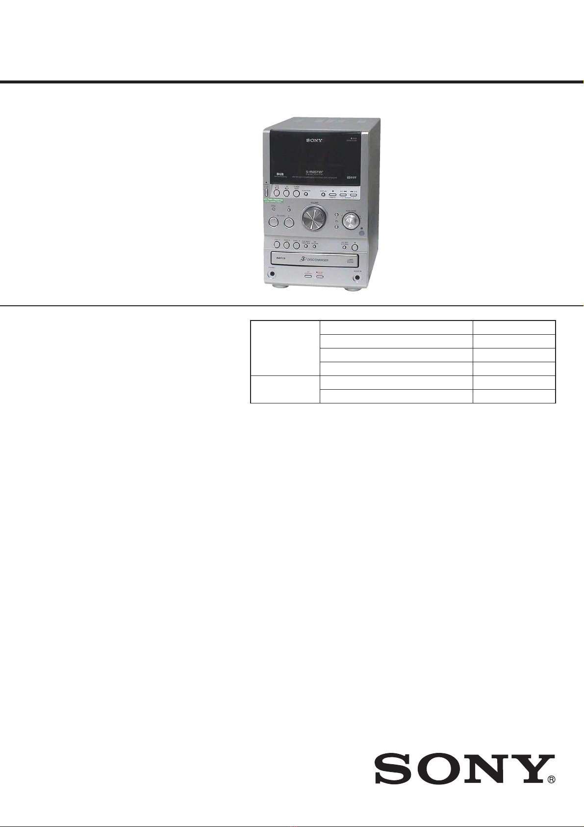
HCD-SPZ90DAB
SECTION 2
GENERAL
This section is extracted from
instruction manual.
Basic Operations
Before using the system
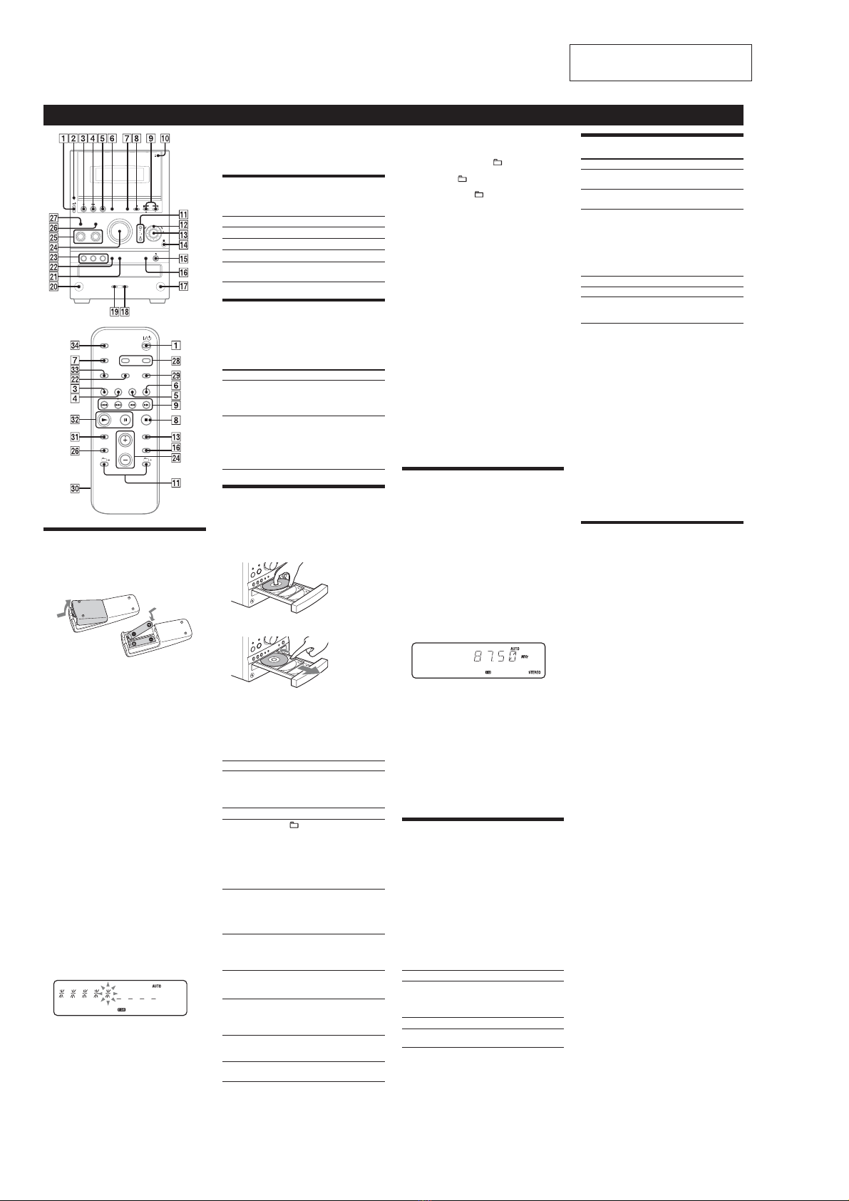
To use the remote
Slide and remove the battery compartment lid , and
insert the two supplied R6 (size AA) batteries, ×side
rst, matching the polarities shown below.
Notes on using the remote
• With normal use, the batteries should last for about six months.
• Do not mix an old battery with a new one or mix dierent types of
batteries.
• If you do not use the remote for a long period of time, remove the
batteries to avoid damage from battery leakage and corrosion.
To set the clock
1Turn on the system.
Press ÒÄÆ (power) ȩ.
2Select the clock set mode.
Press CLOCK/TIMER SET on the remote. If the
current mode appears on the display, press Ã/Ñ
ȱon the remote repeatedly to select “CLOCK SET”
and then press ENTER on the remote.
3Set the time.
Press Ã/Ñȱon the remote repeatedly to set
the hour, and then press ENTER on the remote.
Use the same procedure to set the minute.
e clock settings are lost when you disconnect the
power cord or if a power failure occurs.
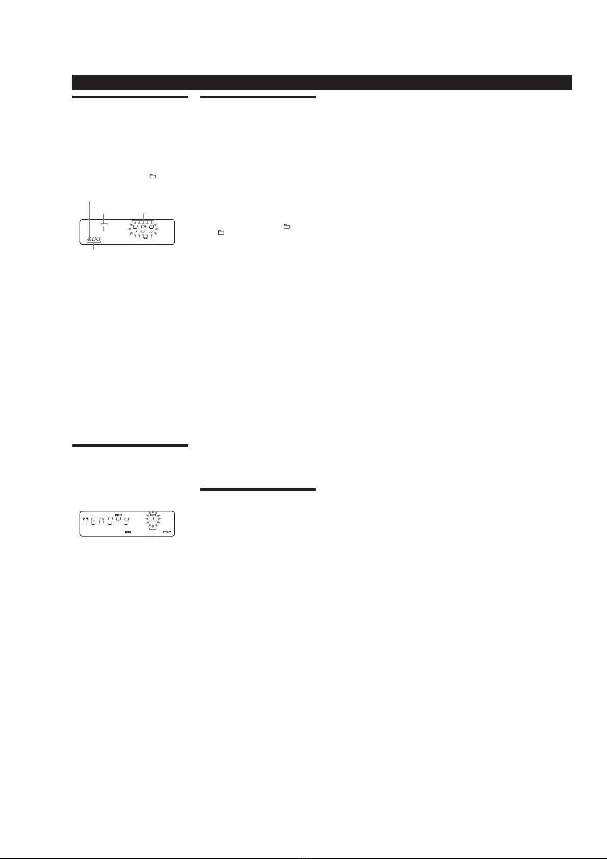
To run the DAB Automatic Scan
When you turn on the system for the rst time aer
you purchase the system, DAB Automatic Scan starts
automatically and creates a list of available services.
If you want to run the DAB Automatic Scan again,
perform the procedure below.
1Press DAB AUTO SCAN on the unit.
“AUTO SCAN” and “PUSH ENTR” appear.
2Press PUSH ENTER on the unit (or ENTER on the
remote) .
Scanning begins. e scanning progress is indicated
by advancing asterisks. Depending on the DAB
services available in your area, scanning may take a
few minutes.
When scanning is complete, a list of available services
is created.
Notes
• If your country or region does not support DAB broadcast, “NO
SERV” appears.
• Do not press any button on the unit or the remote during DAB
Automatic Scan. Scanning is interrupted and service list may not be
created properly. In this case, run the DAB Automatic Scan again.
• If you move to another area, repeat this procedure to store the
stations for your new area.
• is procedure clears all previously stored presets.
• Before unplugging the DAB antenna, make sure the system is turned
o to preserve your own DAB settings.
• is tuner does not support data services.
Selecting a music source
Press the following buttons (or press FUNCTION Ȯ
repeatedly).
To select Press
CD CD Ȭon the remote.
Tuner TUNER/BAND ȭ.
Tape TAPE ȫon the remote.
Component (connected
using an audio cord)
FUNCTION Ȯrepeatedly
until “AUDIO IN” appears.
Adjusting the sound
To adjust the volume
Press VOLUME +/– on the remote (or turn the
VOLUME control on the unit) ɀ.
To add a sound effect
To Press
Generate a more
dynamic sound
(Dynamic Sound
Generator X-tra)
DSGX on the unit.
Set the sound eect EQ repeatedly to select
“BASS” or “TREBLE,” and
then press +/– ȱon the
remote (or EQ LEVEL +/–
on the unit) repeatedly to
adjust the level.
Playing a CD/MP3 disc
1Select the CD function.
Press CD Ȭon the remote.
2Place a disc.
Press ì(CD open/close) ȷon the unit, and place a
disc with the label side up on the disc tray.
To insert additional discs, slide the disc tray with your
nger as shown below.
To close the disc tray, press ì(CD open/close) ȷon
the unit again.
Do not force the disc tray closed with your nger, as
this may damage the unit.
3Start playback.
Press à(play) on the remote (or CD/ā(play/
pause) Ȭon the unit).
To Press
Pause playback ê(pause) on the remote (or
CD/ā(play/pause) Ȭon the
unit). To resume play, press the
button again.
Stop playback Ą(stop) Ȱ.
Select a folder on an
MP3 disc
+/– (select folder) ȳ. Or
turn the jog dial ȴon the unit
and press PUSH ENTER ȵon
the unit (turn the jog dial ȴon
the unit during playback until
“FOLDER” appears, and then
press PUSH ENTER ȵon the
unit to select the desired folder).
Select a track or le Ã/Ñ(go back/go forward)
ȱ. Or turn the jog dial ȴon
the unit and press PUSH ENTER
ȵon the unit. To cancel, press
CANCEL Ȱon the unit.
Find a point in a
track or le
Hold down ù/ß(rewind/
fast forward) ȱduring playback,
and release the button at the
desired point.
Select Repeat Play REPEAT on the remote
repeatedly until “REP” or “REP1”
appears.
Select a disc Press DISC SKIP ȸon the
remote (or DISC 1 – 3 ȿor
DISC SKIP ȸ(in stop mode) on
the unit).
Switch to CD
function from
another source
Press DISC 1 – 3 ȿon the unit
(Automatic Source Selection).
Exchange other discs
while playing
Press EX-CHANGE ȸon the
unit.
To change the play mode
Press PLAY MODE Ⱦrepeatedly while the player is
stopped. You can select normal play (“ALL DISCS” for
all discs, “1DISC” for a disc, or “ *” for all MP3 les in
the folder on the disc), shue play (“ALL DISCS SHUF,”
“1DISC SHUF,” or “ SHUF*”), or program play
(“PGM”).
* When playing a CD-DA disc, (SHUF) Play performs the same
operation as 1DISC (SHUF) Play.
Note on the jog dial
Only the rst 6 characters are displayed when performing the folder
search, track search, or le search.
Notes on Repeat Play
• All tracks or les on a disc are played repeatedly up to ve times.
• You cannot select “REP” and “ALL DISCS SHUF” at the same time.
• “REP 1” indicates that a single track or le is repeated until you stop
it.
Notes on playing MP3 discs
• Do not save other types of les or unnecessary folders on a disc that
has MP3 les.
• Folders that have no MP3 les are skipped.
• MP3 les are played back in the order that they are recorded onto
the disc.
• e system can only play MP3 les that have a le extension of
“.MP3.”
• If there are les on the disc that have the “.MP3” le extension,
but that are not MP3 les, the unit may produce noise or may
malfunction.
• e maximum number of:
– folders is 255 (including the root folder).
– MP3 les is 511.
–
MP3 les and folders that can be contained on a single disc is 512.
– folder levels (the tree structure of les) is 8.
• Compatibility with all MP3 encoding/writing soware, recording
device, and recording media cannot be guaranteed. Incompatible
MP3 discs may produce noise or interrupted audio or may not play
at all.
Notes on playing multisession discs
• If the disc begins with a CD-DA (or MP3) session, it is recognized as
a CD-DA (or MP3) disc, and other sessions are not played back.
• A disc with a mixed CD format is recognized as a CD-DA (audio)
disc.
Listening to the radio
Before you can receive DAB, you must complete the
DAB Automatic Scan procedure (see “Before using the
system”).
1Select “DAB” or “FM.”
Press TUNER/BAND ȭrepeatedly.
2Select the tuning mode.
Press TUNING MODE Ⱦrepeatedly until “AUTO”
appears.
3Tune in the desired station.
Press +/– on the remote (or TUNING +/– on the
unit) ȱ. Scanning stops automatically when a station
is tuned in, and then “TUNED” (DAB only) and
“STEREO” (for stereo programs) appear. When you
tune in a DAB station or an FM station that provides
RDS services, the service name or station name
appears on the display.
To stop automatic scanning (FM band only)
Press Ą(stop) Ȱ.
To tune in a station with a weak signal (FM
band only)
If the scanning does not stop, press TUNING MODE Ⱦ
repeatedly until “AUTO” and “PRESET” disappear, and
then press +/– on the remote (or TUNING +/– on the
unit) ȱrepeatedly to tune in the desired station.
Notes on listening to DAB stations
• When tuning in a DAB station, it may take a few seconds before you
hear any sound.
• Primary service is automatically received when secondary service
ends.
Playing a tape
1Select the tape function.
Press TAPE ȫon the remote.
2Insert a tape.
Press ìPUSH OPEN/CLOSE Ȳon the unit, and
insert the TYPE I (normal) tape into the cassette
holder with the side you want to play facing forward.
Make sure there is no slack in the tape to avoid
damaging the tape or the tape deck. Press ìPUSH
OPEN/CLOSE Ȳon the unit again to close the
cassette holder.
3Start playback.
Press à(play) on the remote (or TAPE/àê
(play/pause) ȫon the unit).
To Press
Pause playback ê(pause) on the remote (or
TAPE/àê(play/pause) ȫon
the unit). To resume play, press the
button again.
Stop playback Ą(stop) Ȱ.
Rewind or fast
forward
ù/ß(rewind/fast forward) ȱ.
Changing the display
To change Press
Information on
the display*
DISPLAY ȯrepeatedly when the
system is on.
Display mode
(See below.)
DISPLAY ȯrepeatedly when the
system is o.
* For example, you can view:
– CD/MP3 disc information such as the track or le number, folder
name (during normal play), or the total play time (while the player
is stopped)
– DAB station information such as the service name, channel label,
preset number, frequency, DLS (Dynamic Label Segment), or
ensemble label
e system oers the following display modes.
Display mode When the system is off,1)
Clock e clock is displayed.
Power Saving
Mode2)
e display is turned o to conserve
power. e timer and clock continue
to operate.
1) e STANDBY indicator lights up when the system is o.
2) When the system is in Power Saving Mode, the following functions
are unavailable:
– setting the clock.
– changing the CD power manage function.
Notes on the display information
• e following are not displayed;
– total playing time for a CD-DA disc depending on the play mode.
– total playing time for an MP3 disc.
– remaining playing time for an MP3 le.
• e following are not displayed correctly;
– elapsed playing time of an MP3 le encoded using a VBR (variable
bit rate).
– folder and le names that do not follow either the ISO9660 Level
1, Level 2 or Joliet in the expansion format.
• e following are displayed;
– ID3 tag information for MP3 les when ID3 version 1 and version
2 tags are used.
– up to 62 characters of ID3 tag information using uppercase letters
(A to Z), numbers (0 to 9), and symbols (" $ % ’ ( ) *+ , – . / < = >
@ [ \ ] _ ` { | } ! ? ^).
– up to 8 characters of service name, up to 128 characters of DLS
(Dynamic Label Segment) and up to 16 characters of ensemble
label using uppercase letters (A to Z), numbers (0 to 9), and
symbols (" $ % ’ ( ) *+ , – . / < = > @ [ \ ] _ ` { | } ! ? ^).
Using optional audio components
To connect an optional headphones
Connect headphones to the PHONES jack ȼon the
unit.
To connect an optional component
Connect additional audio component to the AUDIO
IN jack ȹon the unit using an audio analog cord (not
supplied). Turn down the volume on the system, and
then press FUNCTION Ȯrepeatedly to select the
AUDIO IN function.


 User manual")