Sony WRT-847A User manual

i
Operating Instructions
Mode d'emploi
Bedienungsanleitung
Manual de instrucciones
2000 Sony Corporation
3-205-009-03 (1)
WRT-847A/WRT-847B
UHF Synthesized
Transmitter Unit
GB
FR
DE
ES

ii
Owner’s Record
The model and serial numbers are located at the rear of the
unit. Record the serial number in the space provided below.
Refer to these numbers whenever you call upon your Sony
dealer regarding this product.
Model No. WRT-847A/WRT-847B Serial No.
Notice for customers in the U.S.A.
Use of Sony wireless devices is regulated by the Federal
Communications Commission as described in Part 74
subpart H of the FCC regulations and users authorized
thereby are required to obtain an appropriate license.
You are cautioned that any changes or modifications not
expressly approved in this manual could void your authority
to operate this equipment.

iii
Notice for customers in Canada:
Use of Sony wireless devices is regulated by the Industry
Canada as described in their Radio Standard Specification
RSS-123.
A licence is normally required. The local district office of
Industry Canada should therefore be contacted. When the
operation of the device is within the broadcast band, the
licence is issued on no-interference, no-protection basis with
respect to broadcast signals.
Operation of this device is subject to the following two
conditions: (1) this device may not cause interference, and
(2) this device must accept any interference, including
interference that may cause undesired operation of the
device.
Avis pour les clients au Canada:
L’usage des appareils sans-fil Sony est réglé par l’Industrie
Canada comme décrit dans leur Cahier des Normes
Radioélectriques CNR-123.
Une licence est normalement requise. Le bureau de
l’Industrie Canada doit être contacté. Lorsque l’opération de
l’appareil est dans les limites de la bande de radiodiffusion, la
licence est émanée sur la base de non-interférence, non-
protection avec les signaux de radiodiffusion.
L’utilisation de cet appareil est soumise aux deux conditions
suivantes : (1) cet appareil ne peut causer d’interférences, et
(2) cet appareil doit accepter toutes les interférences, y
compris les interférences capables de provoquer un
fonctionnement indésirable de l’appareil.

iv
Notice for customers in Europe
Spécifications particulières pour les consommateurs européens
Hinweis für Kunden in Europa
Aviso para los usuarios en Europa
U.K. 854.125 - 862 MHz
Germany 798 - 822 MHz
Norway 800 - 820 MHz
Luxembourg 800 - 830 MHz, 854.125 - 862 MHz
Belgium 854.125 - 862 MHz
Denmark 800.100 - 819.900 MHz
France 470 - 830 MHz
Italy 800 - 820 MHz
Sweden 800 - 820 MHz
Switzerland 800 - 820 MHz
Finland 800 - 814 MHz
Iceland 800 - 814 MHz
Austria 774 - 790 MHz
Netherland 774 - 782 MHz
Hereby, Sony Corporation, declares that this WRT-847B is
in compliance with the essential requirements and other
relevant provisions of Directive 1999/5/EC.
Note:
In some countries additional frequency bands may be used
with the agreement of the national authority.
Sony Corporation déclare par la présente que ce WRT-847B
est conforme aux exigences fondamentales et aux autres
dispositions applicables de la Directive 1999/5/CE.
Note :
Des bandes de fréquence supplémentaires peuvent être
utilisées dans certains pays, avec l'accord des autorités
nationales.
Hiermit erklärt die Sony Corporation, daß das Modell
WRT-847B die grundlegenden Anforderungen und sonstigen
relevanten Bestimmungen der Richtlinie 1999/5/EU erfüllt.
Hinweis:
In einigen Ländern können mit dem Einverständnis
nationaler Behörden weitere Frequenzbereiche verwendet
werden.

v
Por la presente, Sony Corporation, declara que este
WRT-847B cumple con los requisitos esenciales y otras
disposiciones pertinentes de la Directiva 1999/5/EC.
Nota:
En algunos países, es posible utilizar bandas de frecuencias
adicionales con el consentimiento de las autoridades
nacionales.
Hinweis für Kunden in der Österreich:
Vor Inbetriebnahme ist die individuelle Genehmigung der
lokalen Behörden für das Telekommunikationsspektrum
erforderlich.
Note for customers in Switzerland:
Before use, a request of concession for a wireless
microphone (Frequency Class 3) has to be submitted to
Bakom.
Note concernant les utilisateurs en Suisse:
Une demande de concession de microphone sans fil
(fréquence classe 3) doit être présentée au Bakom avant
d'utiliser l'appareil.
Hinweis für Kunden in der Schweiz:
Vor Inbetriebnahme ist eine Konzessionsanforderung für ein
drahtloses Mikrofon (Frequenzklasse 3) bei Bakom
einzureichen.
Note for customers in Finland:
To own and use, it is necessary to obtain an individual
licence of the Telecommunications Administration
Center.
Hinweis für Kunden in der Luxemburg:
Vor Inbetriebnahme eines Geräts müssen die Frequenzen
gegebenenfalls nach den geltenden Vorschriften vor dem
Gebrauch von der “ILT” zugewiesen werden.
Nota per i clienti in Italia
L’uso del prodotto sul territorio italiano è soggetto alle
regolamentazioni del Codice Postale e delle
Telecomunicazioni art. 334.
Hinweis für Kunden in der Deutschland:
Vor Inbetriebnahme muß bei der zuständigen Außenstelle
der Regulierungsbehörde (Reg TP) eine Kanalzuweisung
beantragt werden.

vi
Note for customers in Norway:
Using this transmitter with 50 mW RF output power requires
the frequency license.
Note for customers in Belgium:
Using this transmitter with 50 mW RF output power is not
allowed. Be sure to set the RF output power to 10 mW.
Note concernant les utilisateurs en Belgique:
L’emploi de ce transmetteur avec une puissance de sortie RF
de 50 mW n’est pas autorisé. Bien régler la puissance de
sortie RF à 10 mW.
Hinweis für Kunden in Belgien:
Der Einsatz des Senders mit einer HF-Ausgangsleistung von
50 mW ist verboten. Betreiben Sie den Sender ausschlieβlich
mit einer HF-Ausgangsleistung von 10 mW.

1(GB)
English
English
GB
• The unit is designed for use in ambient temperature range
of 0°C to 50°C (32°F to 122°F).
• Do not place the unit on or near heat sources, such as
lighting equipment, power amplifiers, or in a place subject
to direct sunlight or excessive moisture. In such places,
the external finish or internal parts of the unit may be
damaged.
• If the unit is used in a very humid or dusty place or in a
place subject to expose to an active or corrasive gas, clean
its surface as well as the connectors with a dry, soft cloth
soon after use.
Lengthy use of the unit in such places or not cleaning it
after its use in such places may shorten its life.
• When cleaning the unit, never use organic solvents such as
thinners or benzine, which will damage the finish of the
unit.
• Using the unit with wet hands may cause trouble in the
unit.
• The unit has been factory adjusted precisely. Do not
tamper with its internal parts or attempt to repair it.
• Make sure to use two LR6 (size-AA) alkaline batteries.
• Make sure the poles of the batteries match the + and –
markings in the battery holder.
• Remove the batteries when the unit will not be used for a
long period of time.
• Do not attempt to recharge the alkaline batteries.
• Do not dispose of the batteries in fire. Do not disassemble
or short-circuit the batteries.
Precautions
Table of Contents
Precautions................................................................ 1
Introduction ............................................................... 2
Features ..........................................................2
Parts Identification.................................................... 4
Power Supply ............................................................ 7
Settings ...................................................................... 8
Initiating Setting Mode ..................................8
Changing the Transmitting Channel ..............9
Changing the Audio Gain Setting ................10
Resetting the Accumulated
Battery Use Time Indication ..................11
Changing the Compander Time Constant....11
Changing the RF Output Power ...................12
Troubleshooting ...................................................... 13
Specifications.......................................................... 15
Error Messages ....................................................... 16

2(GB)
Introduction
Coupling with the CU-F780, CU-G780, CU-E700, CU-E672
or CU-F117 Sony Microphone Capsule Unit, the WRT-847A/
847B UHF-synthesized transmitter unit makes up a UHF-
synthesized wireless microphone to be used in a UHF-
synthesized wireless microphone system.
For vocal concentration, operate the WRT-847A/847B in
conjunction with the WRR-802A/850A, MB-806A with
WRU-806A UHF Synthesized Tuner. For vocal and
interview use, operate the WRT-847A/847B in conjunction
with the WRR-805A/855A UHF Synthesized Tuner.
The microphone/transmitter and tuners of the wireless
microphone system are classified by frequency band.
A 24 MHz frequency band (a 14 MHz frequency band:
model available in Australia) is assigned to each
microphone/transmitter and tuner model.
In building up a UHF wireless microphone system, be sure
to combine a microphone/transmitter and a tuner having the
same TV channel number.
Features
Selectable microphone capsules
To make up suitable wireless microphones for your use, five
microphone capsule units are available as optional
accessories. The capsule units for the WRT-847A/847B are;
CU-F780 Super Cardioid Dynamic Microphone Unit
CU-G780 Super Cardioid Dynamic Microphone Unit
for Live Vocal Performance
CU-E700 Super Cardioid Electret Condenser
Microphone Unit
CU-E672 Hyper Cardioid Electret Condenser
Microphone Unit (Short-shotgun)
CU-F117 Omni-directional Dynamic Microphone Unit
The capsule unit can be mounted simply by screwing it into
the transmitter.
Phase Locked Loop (PLL) synthesized system
The WRT-847A/847B features a refined phase locked loop
(PLL) synthesizer circuit.
Wide dynamic range and low noise
The compander (compressor/expander) system enables
transmission over a wide dynamic range with minimum
noise. The compander time constant is selectable to get the
optimum sound quality of the individual microphone
capsule.

3(GB)
Selectable RF output
The RF output power can be adjusted to high (50 mW) or
low (10 mW) to match the environment where it will be
used; to obtain a wide service area, set this to 50 mW, and
when using the transmitter in a simultaneous multi-channel
system, set it to 10 mW.
Highly reliable audio gain level adjustment
With an adjustable range of –12 dB to +9 dB in 3 dB steps,
the built-in input level volume reduces signal distortion
during the input of excessively strong audio signals. It can
raise the input gain during too low audio input.
POWER switch with holding function
The POWER switch can be locked in the ON position to
protect against accidental power cutoffs.
Powered by readily available battery type
The built-in, high-efficiency DC-DC converter provides
about eight hours of continuous and stable operation with
two LR6 (size-AA) alkaline batteries.
Low-battery notification on the unit and the tuner
When the transmitter batteries are low, the transmitter sends
a warning to the WRR-802A/805A/850A, MB-806A with
WRU-806A in the form of “Battery status information.”
This information is sent to the WRR-802A/805A/850A,
MB-806A with WRU-806A about one hour before the
batteries go dead to allow the batteries to be safely replaced.
When the WRR-802A/805A/850A, MB-806A with
WRU-806A receive this information, the LED and the
LCD1) display on tuner panel start to flash.
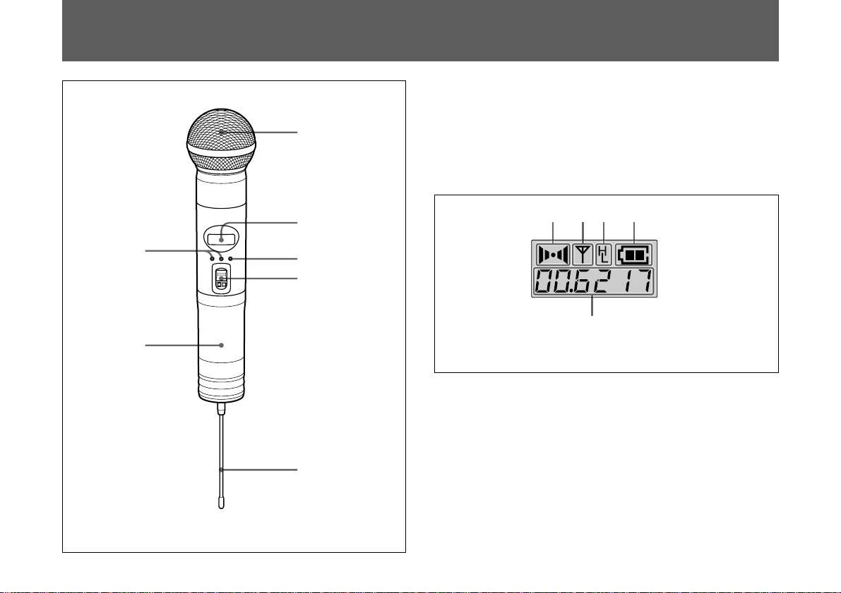
LCD1) read-out of various information
The transmitter's LCD1) display shows the current channel
number, frequency, audio gain, compander time constant,
RF output settings and residual battery power.The
accumulated battery use time is also indicated (in one-
minute increments) to allow precise monitoring of battery
use.
Automatic saving of channel, audio gain and RF
output settings
All channel, audio gain, compander time constant, and RF
output settings are automatically saved when the transmitter
is turned off, thus eliminating the need to make the same
settings again the next time you use the transmitter.
Tone signal-incorporated RF carrier signal
The transmitter sends an RF carrier signal that incorporates
a tone signal to enable any tuner with a tone squelch circuit
to pick out only the target audio signal.
Notes on simultaneous multi-channel
operation
When operating two or more transmitters simultaneously in
a multi-channel system, please note the following.
• Set the RF output power of the transmitters to 10 mW.
• Keep the transmitters separated from each other by a
distance of at least 30 cm (1 foot).
• Keep the transmitters at least 3 meters (10 feet) away from
the receiving antenna.
1)LCD: Liquid-crystal display
.............................................................................................................................................................................................................................................................

4(GB)
Parts Identification
1Microphone capsule unit (not supplied)
Mount the microphone capsule unit (CU-F780, CU-G780,
CU-E700, CU-E672 or CU-F117) securely.
See the instruction manual supplied with your microphone
capsule unit for mounting.
2Liquid-crystal display (LCD)
AAF (audio input) indication
Lights whenever an audio signal stronger than the reference
level is received.
BRF (antenna output) indication
Lights during signal transmission from the antenna.
CPower (RF power) indication
Shows the RF power setting.
See “Changing the RF Output Power” on page 12.
AB DC
E
AF RF BATT
1
In the figure, the CU-F780 capsule unit (not supplied)
is mounted on the WRT-847A/847B as an example.
2
3
4
5
6
7
Channel indication Eshows
that of the CE62 model as
an example.

5(GB)
DBATT (battery) indication
Shows the battery condition.
See “Battery indication” on page 7.
ECH (channel) indication
Displays the transmitting channel.
Each time you press the SET button in Transmitting mode,
the channel indication changes as follows.
Display of the transmitting channel/frequency
shows that of the CE62 model as an example.
Transmitting
channel
Transmitting
frequency
Audio gain level
Accumulated
battery use time
Press SET
button.
Transmitting channel: The current transmitting channel
setting.
Transmitting frequency: The current transmitting
frequency setting.
Audio gain level: The input gain level setting in decibels.
Can be set within a range of –12 dB to +9 dB in 3-dB
steps.
Accumulated battery use time: The accumulated time of
battery use (in 1-minute increments).
Compander time constant: “ L” means the long time.
“ S” means the short time.
To adjust these parameters, see “Settings” from page 8 to
12.
3SET button
In Transmit mode, press this button to change the indicated
items in the lower half of the LCD display.
To change the settings on each item, set the transmitter in
the Setting mode as follows: Turn the POWER switch to
ON while holding the SET button down. Then press the
SET button to select the items to be changed, and press the
+/– buttons to change the settings.
For details on Setting mode, see “Settings” on page 8.
Compander time
constant

6(GB)
Parts Identification
4POWER switch
Turns the transmitter ON or OFF.
When you set this switch to ON without holding down the
SET button, the transmitter enters Transmitting mode, and
the signal of the selected channel is transmitted.
The HOLD switch appears when the POWER switch is set
to ON.
Set the HOLD switch to the lock position to prevent an
accidental power cutoff during microphone operation.
Locking the POWER switch
5Antenna
Slide the HOLD switch to the
right with a ballpoint pen or
similar item.
A yellow line appears when
the switch is in the hold
position.
6Battery holder
Insert the batteries here.
For details on inserting the batteries, see “Power Supply”
on page 7.
7+ (+ selection) / – (– selection/reset) buttons
In Setting mode, use these buttons to select the transmitting
channel/frequency, audio gain level, compander time
constant, and RF power level.
Use the – button to reset the accumulated battery use time
indication to 00:00.
For details on Setting mode, see “Settings” from page 8 to
12.
How to press the SET and +/–buttons
ON
HOLD
ON
HOLD
Green line Yellow line
+
SET
–
To pess the SET, +/–buttons
use a ballpoint pen or similar
item.

7(GB)
Good
Power Supply
2Match two batteries to the polarity markings and insert
them into the battery holder.
3Close the battery holder and lock the grip by turning it
in the opposite direction of the arrow.
Battery indication
When you turn the power on, the battery condition is
indicated by the BATT indication in the LCD display.
The transmitter can operate on two LR6 (size AA) alkaline
batteries continuously for about eight hours (at 10 mW RF
power, 25 ºC / 77ºF).
Inserting the batteries
1Turn the grip in the direction of the arrow to open the
battery holder.
1234
BATT
indication
Lights Lights Flashes Goes off
Battery
condition Less than
half-charge Almost
exhausted Completely
exhausted
Note
The indication may be incorrect if the two batteries are not
new when inserted. If you plan to use the transmitter for a
long period, replace both batteries with new ones at the
same time.
2
1,3

8(GB)
For the transmitting channels and frequencies selectable on
your transmitter, see the “Sony Wireless Microphone System
Frequency List” supplied with this manual.
Initiating Setting Mode
Enter Setting mode to change the transmitting channel, the
transmitting frequency, the audio gain level, the compander
time constant and the RF output power, or to reset the
accumulated battery use time indication.
To enter Setting mode
While holding down the SET button, set the POWER switch
to ON.
Hold the SET button down until an indication appears on the
LCD display.
The transmitter enters Setting mode and the indication
before the transmitter was previously turned OFF flashes on
the LCD display.
Pressing the SET button cycles the setting modes in the
order shown in the figure on the right column.
Note
On the model available in Europe, the transmitting channels
are grouped in four sets as shown in “Sony Wireless
Microphone System Frequency List”.
Settings
Transmitting
channel1)
Transmitting frequency
Audio gain level
Accumulated battery use
time
Press SET
button.
Compander time
constant
RF output power
1) On the model available in Europe, the transmitting-
channel indication flashes in two steps; first, the left two
digits flash for setting the channel-group number, then the
remaining four digits flash for setting the channel number.
Display of the transmitting channel/frequency shows that of the
CE62 model as an example.

9(GB)
The right four digits starts to flash for channel
number selection.
3) Select the channel number by pressing the + or –
button.
4) When the desired channel number appears, press the
SET button.
3When the desired channel number (or frequency)
appears, set the POWER switch to off position to
release Setting mode, or press the SET button to
continue operations in Setting mode.
Changing the Transmitting Channel
The transmitting channel can be selected through either the
channel number or the frequency.
1Set the transmitter to Setting mode.
If the channel number (or frequency) indication does not
appear, press the SET button until the channel number
(or frequency) indication appears.
2Press the + or – button to select the channel number (or
frequency).
Pressing the + button cycles the indication in the order
shown in the tables in the “Sony Wireless Microphone
System Frequency List” supplied with the manual.
Pressing the – button cycles the indications in the
opposite direction.
Hold down the button to change the channel number (or
frequency) quickly.
Note on the model available in Europe
On the model available in Europe, select the group
number before selecting the channel number as follows.
1) When the left two digits flashes, select the group
number by pressing the + or – button.
2) When the desired group number appears, press the
SET button.
Group selection
mode Frequency
selection mode
Channel
selection mode
Group, channel and frequency selection examples for the
model available in Europe (CE62)
m: + button M : –button

10(GB)
The next time you turn on the transmitter (by setting the
POWER switch to ON), the transmitter will enter
Transmitting mode with the selected channel number (or
frequency).
Notes
• The transmitter cannot transmit in Setting mode.
• Make sure that the channel selected on the transmitter is
the same as that selected on the tuner being used in the
same system.
• Depending on the noise or interference conditions, all
selectable channels may not be usable. If necessary, you
can determine which channels are usable by cycling the
channel selection through a number of channels on the
tuner with the unit set to OFF. Those channels for which
the RF indicator on the tuner does not light are usable.
• The transmitter may not operate correctly if it is turned on
immediately after being turned off in Setting mode. Wait
for a few seconds before turning the power on again.
• The channel numbers and frequencies of your transmitter
are shown on the “Sony Wireless Microphone System
Frequency List” supplied with the manual.
Settings
AF RF BATT AF RF BATT
Changing the Audio Gain Setting
You can change the audio input gain within a range of
–12 dB to +9 (in 3-dB steps) in either Setting mode or
Transmitting mode.
When the audio input is excessively strong and distortion
occurs, reduce the input gain by setting it to “–12 dB” to
“–3 dB”. When the audio input is excessively low, raise the
input gain by setting it to “+3 dB” or “+9 dB”. The factory
preset setting is “0 dB”.
Changing the audio gain in Setting mode
1Set the transmitter to Setting mode.
2If the audio gain indication (“GAIN-” or “ATT-”) is not
displayed, press the SET button until it appears.
3Press the + or – button to change the audio gain setting.
Hold down the button to change the level quickly.
+ button
–button

11(GB)
2If the accumulated battery use time (for example
“01:50”) is not displayed, press the SET button until it
appears.
3Press the – button.
The indication resets to 00:00.
To go back to the previous value, press the + button
while the “00:00” indication is on.
4Set the POWER switch to the off position to release
Setting mode, or press the SET button to continue
operations in Setting mode.
Changing the Compander Time Constant
The transmitter provides two levels of the compander time
constant to get the best sound quality of the microphone
capsule unit.
The recommended settings are;
“S” (short) : CU-F780 / G780
“L” (long) : CU-E700 / E672 / F117
4Once the desired level appears, set the POWER switch
to off position to release Setting mode, or press the SET
button to continue operations in Setting mode.
The next time you turn on the transmitter (by setting the
POWER switch to ON), the transmitter enters Transmitting
mode with the audio gain selected.
Changing the audio gain in Transmitting mode
You can also change the audio gain while transmitting.
1If the audio gain indication is not displayed, press the
SET button until it appears.
2Press the + or – button to change the audio gain setting.
Resetting the Accumulated Battery Use
Time Indication
The accumulated battery use time is the total time (in hours
and minutes) the batteries have been used. It is recorded
whenever the transmitter is on.
Reset the indication to “00:00” whenever you replace the
batteries.
1Set the transmitter to Setting mode.
AF RF BATT AF RF BATT
–button

12(GB)
Settings
1Set the transmitter to Setting mode.
2If the compander time constant indication (“TC: S” or
“TC: L”) is not displayed, press the SET button until it
appears.
3Press the + or – button to change the TC setting.
4Once the desired indication appears, set the POWER
switch to the off position to release Setting mode, or
press the SET button to continue operations in Setting
mode.
The next time you turn on the transmitter (by setting the
POWER switch to ON), the transmitter enters the TC setting
selected.
Changing the RF Output Power
You can select the RF output power from two levels of
50 mW or 10 mW in Setting mode.
Check “H” or “L” indication on the upper half of the LCD
display. “H” means 50 mW output. “L” means 10 mW output.
If you want to change the RF output power, proceed the
following steps.
1Set the unit to Setting mode.
2To change the setting from “H” to “L” (or vice versa),
press the SET button until “Po: H” ( or “Po: L” )
appears on the lower half of the display.
3Press the + or – button to change the RF power output.
4Once the desired indication appears, set the POWER
switch to the off position to release Setting mode, or
press the SET button to continue operations in Setting
mode.
The next time you turn on the transmitter (by setting the
POWER switch to ON), the transmitter enters Transmit
mode with the RF output power selected.
AF RF BATT AF RF BATT
+ button
–button
AF RF BATT AF RF BATT
–button
+ button

13(GB)
The transmitter cannot be turned off.
Symptom
Troubleshooting
If you have any problem using the transmitter, use the following checklist. Should any problem persist, consult your Sony
dealer.
Meaning/Remedy
The transmitter does not turn on. •The + and –poles of the batteries do not match those of the battery compartment. bInsert the
batteries with the poles correctly matched.
•The batteries are exhausted. bReplace the batteries with new ones.
•The battery terminals in the transmitter are dirty. bClean the + and –terminals with a cotton swab.
The batteries run down quickly. •The batteries are exhausted. bReplace the batteries with new ones.
•A manganese batteries are being used. bUse the alkaline batteries. The battery life of a
manganese battery is less than half that of an alkaline battery.
•The transmitter is being used under cold conditions. bThe batteries run down quickly under cold
conditions.
The HOLD switch is in the HOLD position. bMove the HOLD switch to the left so that the green line
appears.
The channel cannot be changed. An attempt was made to change the channel by pressing the SET button only. bTurn the
transmitter off, then turn it on again while holding down the SET button. Then change the channel
with the + and –buttons.
There is no sound. •The indication on the LCD is flashing. bThe transmitter is in channel setting mode. Turn the
power off, then on again.
•The channel setting on the transmitter is different from that on the tuner. bUse the same channel
setting for both the transmitter and tuner.
•The AF or RF indicator does not turn on. bConfirm that the transmitter and tuner are both turned
on.

14(GB)
Symptom Meaning/Remedy
Troubleshooting
The sound is weak. •The audio gain level is too low. bThe output level is low. Press the + button in audio gain level
setting mode to raise the gain level.
•The volume on the amplifier, mixer or tuner is low. bAdjust the volume.
There is distortion in the sound. The audio gain level is too high. bThe input level is extremely high. Press the –button in audio gain
level setting mode to lower the gain level.
There is sound interruption or
noise. •The receiver's antenna is incorrectly connected. bConnect the antenna correctly according to the
operation manual of the tuner or antenna divider.
•The antenna divider is turned off. bTurn the antenna divider on. It is possible for the tuner to
receive signals even when the antenna divider is turned off, but sound interruption or noise may
occur.
•The RF indicator on the tuner lights even when the transmitter is off. bJammed transmissions are
being received.
Determine which channels are usable (i.e., channels for which the RF indicator on the tuner does
not light) and set the tuner and transmitter to the same usable channel.
•Two or more wireless microphones/transmitters are set to the same channel. bMake sure no two
microphones/transmitters are set to the same channel. Set each microphone/transmitter to a
different channel.
Other manuals for WRT-847A
1
This manual suits for next models
1
Table of contents
Languages:
Other Sony Transmitter manuals

Sony
Sony IFT-AV1 User manual

Sony
Sony WRT-805A User manual

Sony
Sony TMR-BT10 - Bluetooth Wireless Audio... User manual

Sony
Sony TMR-PJ1 User manual

Sony
Sony S-AIR EZW-T100 User manual

Sony
Sony TMR-IF130 User manual

Sony
Sony T310UG User manual

Sony
Sony STWA-C101 User manual

Sony
Sony DWTP01N/14 User manual

Sony
Sony TMR-PJ2 User manual
Popular Transmitter manuals by other brands

Berker
Berker 2721 Series Operation and assembly instructions

DIW
DIW DMS-20 instruction manual

Optex
Optex SS Checker SC-T4 instruction manual

Endress+Hauser
Endress+Hauser Liquiline Compact CM82 Brief operating instructions

AMG
AMG AMG2683 instruction manual

dji
dji Transmission High-Bright Monitor Combo manual