Parts Identification
26
ARF (radio frequency) indications
The number of dots indicates the RF
input level.
BAF (audio frequency) indication
Appears whenever the output audio
signal is stronger than the reference
level.
CBATT (battery) indication
Shows the battery condition.
For details, see “Power Supply” on
page 30.
DCH (channel) indication
Shows the reception channel. Each
time you press the SET button, the
channel indication changes as follows.
For details, see “Settings” on page 38.
5+ (+ selection) / – (– selection/
reset) buttons
Press these buttons to set the reception
channel and frequency. The “–”
button resets the accumulated battery
use time to “00:00”. These buttons can
also be used to adjust the monitor
level.
6Battery compartment
Accommodates two LR6 (size AA)
alkaline batteries.
For details on how to insert the
batteries, see “Power Supply” on
page 30.
7SET button
Press to change display parameters.
For details, see “Settings” on page
38.
8POWER switch
Turns the power of the tuner ON or
OFF.
9OUTPUT (audio output)
connector (3.5-mm diameter stereo
mini jack)
Connect one end of the supplied XLR-
BMP conversion cable or the stereo
mini plug-BMP conversion cable here
and the other end to the microphone
input on a camcorder, mixer, or
amplifier. If the microphone input
connector on the device connected to
the tuner is a stereo mini jack, connect
the straight (BMP) plug to the tuner
and the L-shaped (stereo mini) plug to
the microphone input connector on the
device.
AF
RF BATT
CH
AB
D
C
The Dchannel indication for
U66 model is shown.
Reception
channel
Reception
frequency
Accumulated
battery use
time
Press
the
SET
button.
The channel/frequency indications for
U66 model are shown.
WIRELESS LAPEL MICROPHONES
25
DBATT (battery) indication
Shows the battery condition.
For details, see “Power Supply” on
page 30.
ECH (channel) indication
Shows the transmission channel. Each
time you press the SET button, the
channel indication changes as follows.
For details, see “Settings” on page
38.
5+ (+ selection) / – (– selection/
reset) buttons
Press these buttons to set the
transmission channel, frequency, or
attenuation level of the input signal.
The “–” button resets the accumulated
battery use time to “00:00”.
6SET button
Press to change display parameters.
For details, see “Settings” on page
38.
Transmission
channel
Transmission
frequency
Attenuation
level of the
input signal
Accumulated
battery use
time
Press
the
SET
button.
The channel/frequency indications for
U66 model are shown.
Portable diversity tuner
(URX-P1)
1Antennas a/b
The angle of the antennas can be
adjusted manually.
2MONITOR connector (3.5-mm
diameter stereo mini jack)
To monitor the tuner output, connect
the headphones to this connector.
3RF (radio frequency) indicator
The color indicates the strength of the
RF input signal.
On in green: RF input is 15 dBµ*
or more.
Off: RF input is less than 15 dBµ*.
4Display section
......................................................................................................................................................................
* 0 dBµ = 1 µVEMF
25
DBATT (battery) indication
Shows the battery condition.
For details, see “Power Supply” on
page 30.
ECH (channel) indication
Shows the transmission channel. Each
time you press the SET button, the
channel indication changes as follows.
For details, see “Settings” on page
38.
5+ (+ selection) / – (– selection/
reset) buttons
Press these buttons to set the
transmission channel, frequency, or
attenuation level of the input signal.
The “–” button resets the accumulated
battery use time to “00:00”.
6SET button
Press to change display parameters.
For details, see “Settings” on page
38.
Transmission
channel
Transmission
frequency
Attenuation
level of the
input signal
Accumulated
battery use
time
Press
the
SET
button.
The channel/frequency indications for
U66 model are shown.
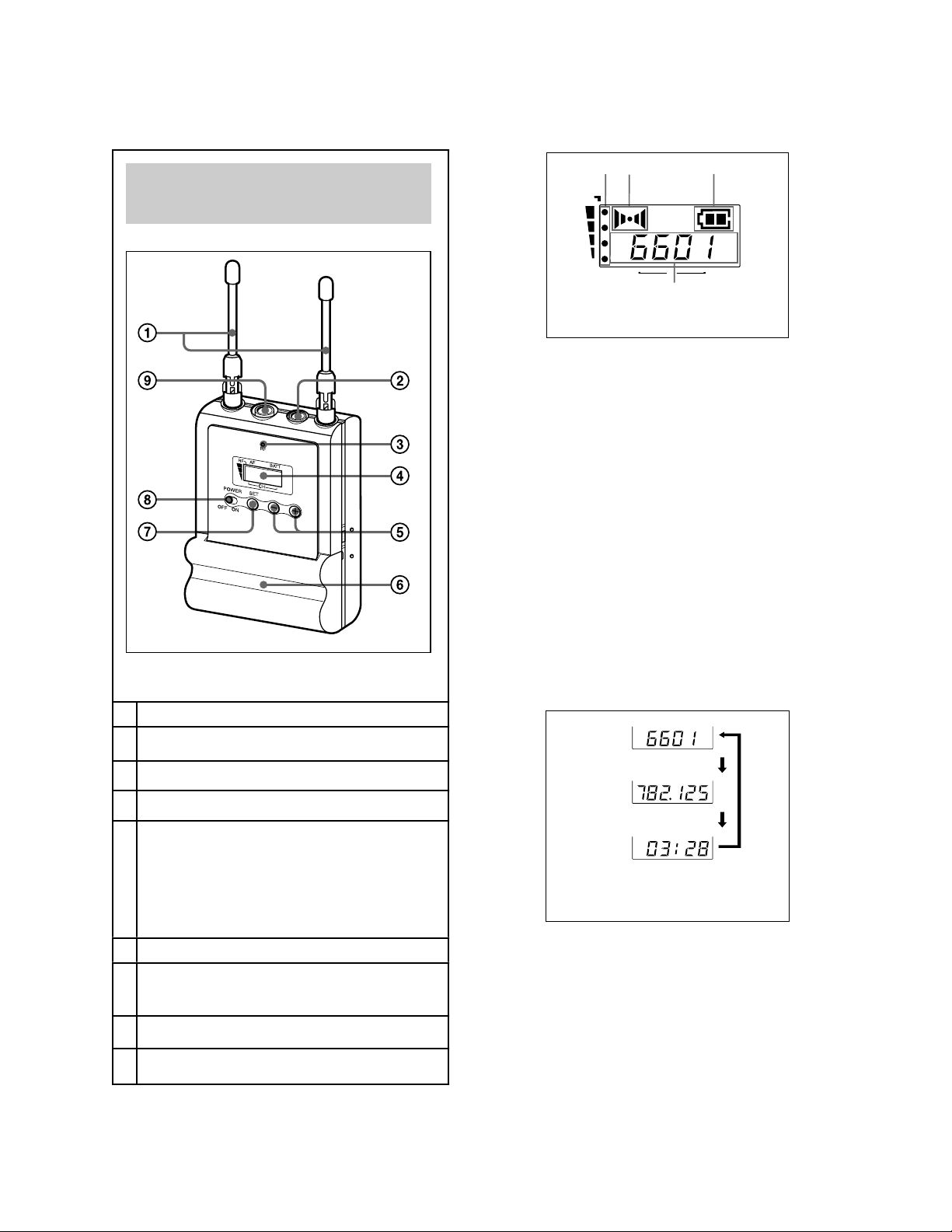
Portable diversity tuner
(URX-P1)
1Antennas a/b
The angle of the antennas can be
adjusted manually.
2MONITOR connector (3.5-mm
diameter stereo mini jack)
To monitor the tuner output, connect
the headphones to this connector.
3RF (radio frequency) indicator
The color indicates the strength of the
RF input signal.
On in green: RF input is 15 dBµ*
or more.
Off: RF input is less than 15 dBµ*.
4Display section
......................................................................................................................................................................
* 0 dBµ = 1 µVEMF
lapel mic input connector
+ (+ selection) / – (– selection/ reset) buttons
Press these buttons to set the transmission
channel, frequency, or attenuation level of the
input signal. The “–” button resets the
accumulated battery use time to “00:00”.
SET button - press to change and
enter display parameters


