1-2 WRR-862A/862B
1
(GB)
Precautions
English Table of Contents
•
The unit is designed for use in ambient temperature range
of 0°C to 50°C (32°F to 122°F).
•
Do not place the unit on or near heat sources, such as
lighting equipment, power amplifiers, or in a place subject
to direct sunlight or excessive moisture. In such places,
the external finish or internal parts of the unit may be
damaged.
•
If the unit is used in a very humid or dusty place or in a
place subject to an active or corrosive gas, clean its
surface as well as the connectors with a dry, soft cloth
soon after use.
Lengthy use of the unit in such places or not cleaning it
after its use in such places may shorten its life.
•
When cleaning the unit, never use organic solvents such
as thinners or benzine, which will damage the finish of the
unit.
•
The unit has been factory adjusted precisely. Do not
tamper with its internal parts or attempt to repair it.
Precautions ......................................................................... 1
Overview............................................................................. 2
Features .......................................................................... 2
Parts Identification ............................................................ 3
Power Supply ..................................................................... 6
Settings................................................................................ 7
Wireless Channel Selection ........................................... 7
Setting the Squelch Level ............................................ 10
Resetting the Accumulated Time Indication ............... 11
Selecting the Backlight Mode...................................... 12
Error Messages ................................................................ 12
Specifications.................................................................... 13
Appendix .......................................................................... 15
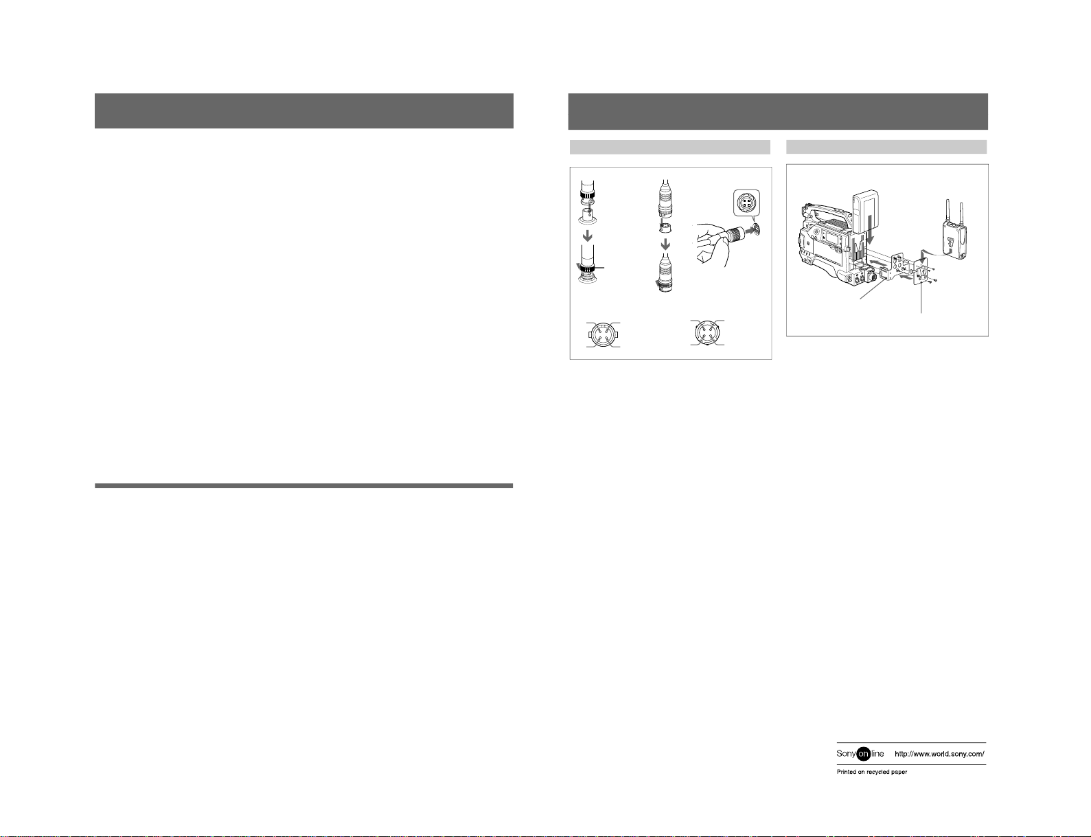
Connections ................................................................. 15
Attaching to a Camcorder ............................................ 15
2
(GB)
WRR-862A
Model available in Australia: 792 to 806 MHz, TV channels 66 to 67
WRR-862B
Model available in USA: 470 to 806 MHz, TV channels 14 to 69 (14
frequency band, divided into 24 MHz range. All 14 frequency bands
may not be available in some areas.)
Model available in Europe: 470 to 862 MHz, TV channels 21 to 69 (17
frequency band, divided into 24 MHz range. All 17 frequency bands
may not be available in some areas.)
Compact, lightweight and easy to mount on Sony
camcorders
The WRR-862A/862B is extremely compact and
lightweight, housing in the rugged, die-cast magnesium
case. It is easily mounted on Sony camcorders.
Preprogrammed wireless channel plans for simultaneous
multi channel operation
The WRR-862A/862B has many preprogrammed channel
groups, meaning combination of wireless channels to permit
simultaneous operation of multiple channels without
intermodulation.
See “Wireless Microphone System Frequency List” supplied
with this manual.
Extensive information by the LEDs and LCD display
The LEDs indicate each channel RF input level (green/ red
indication), diversity reception status, and transmitter
battery alarm. The LCD display for each tuner indicates the
Overview
The WRR-862A/862B is a highly reliable diversity tuner for
the Sony UHF wireless microphone system to be used for
broadcast or movie production purposes.
This tuner is suitable for Electronic News Gathering (ENG)
and Electronic Field Production (EFP).
The microphone/transmitter and tuners of the wireless
microphone system are classified by frequency band.
In building a UHF wireless microphone system, be sure to
combine a microphone/transmitter and a tuner having the
same wireless channel (frequency).
Features
Dual Diversity Tuner
Despite of its compact design, the WRR-862A/862B
simultaneously receives two signal channels. A space
diversity system is employed on both channels to eliminate
signal dropout and provide stable reception. Two SMC9-4S
(Sony 4 pin) audio output connectors are provided on the
top panel.
Wide Operating Frequency ranges
The WRR-862A operates over a 14 MHz frequency band
within the range of 792 MHz to 806 MHz (model available
in Australia) , while the WRR-862B operates over a 24 MHz
frequency band between 470 MHz to 806 MHz (model
available in U.S.A.), or 470 MHz to 862 MHz (model
available in Europe).
3
(GB)
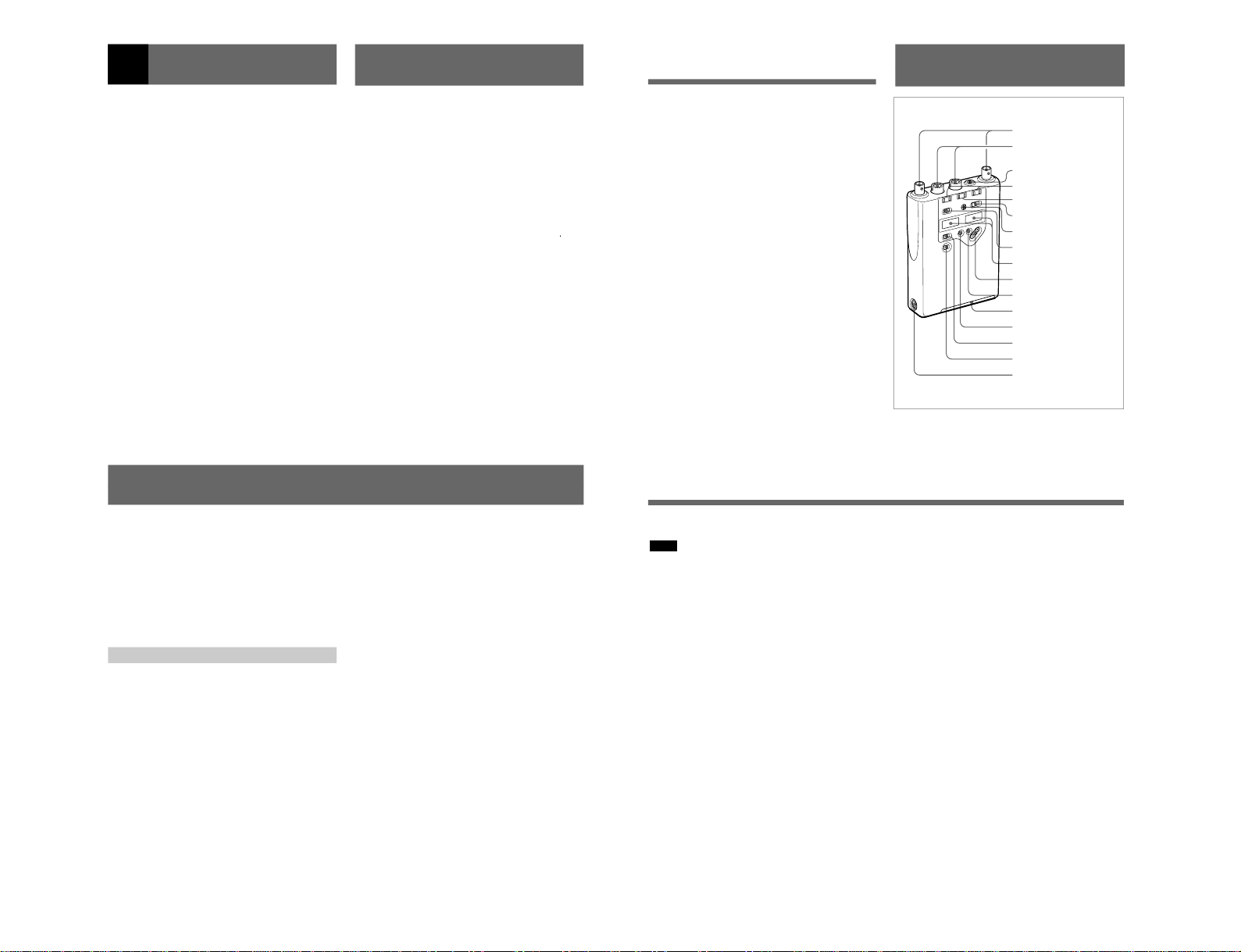
Parts Identification
operating channel/frequency, AF output level, RF input
level, battery status of the tuner, and the accumulated
operating time.
Long operating time
Approximate five hours of continuous operation is provided
by using four LR6 (size AA) alkaline batteries. The WRR-
862A/862B can also be operated on the external power from
Sony camcorders via the supplied DC cable.
Switchable RF squelch
The RF squelch can be easily turned ON or off with the
panel button. The RF squelch level is selectable from 5 dBµ,
10 dBµand 15 dBµ.
Output monitoring
Monitoring of the tuner 1, the tuner 2, or mixed 1 and 2
output is selectable. The monitor volume is adjustable with
a knob.
Overview
qg
DC 12V IN connector
1
ANT a/b connectors
2
OUTPUT 1/2 (BAL)
connectors
3
MONITOR connector
4
RF indicators
5
TX BATT indicators
8
SQUELCH switch
7
MONITOR volume
6
MONITOR switch
9
Display section
qd
CONTROL switch
qs
MODE button
qa
SET button
0
+/–buttons
qf
POWER switch
Battery holder
4
(GB)
Parts Identification
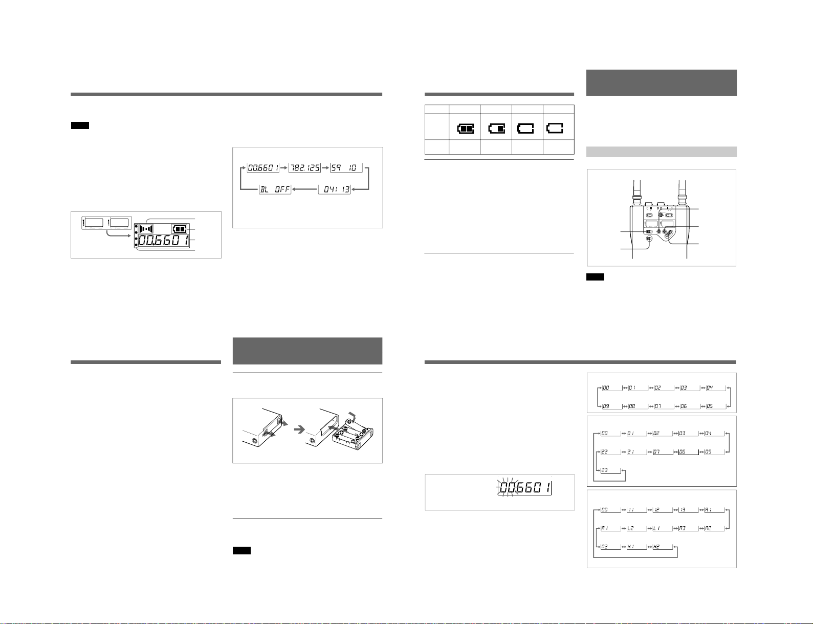
the squelch level setting.
When the squelch level is set to 5 dBµ;
On in green: RF input is more than 15 dBµ.
On in red: RF input is between 5 dBµand 15 dBµ.
Off: RF input is less than 5 dBµ.
When the squelch level is set to 10 dBµ;
On in green: RF input is more than 20 dBµ.
On in red: RF input is between 10 dBµand 20 dBµ.
Off: RF input is less than 10 dBµ.
When the squelch level is set to 15 dBµ;
On in green: RF input is more than 25 dBµ.
On in red: RF input is between 15 dBµand 25 dBµ.
Off: RF input is less than 15 dBµ.
5TX BATT (transmitter battery) indicators
Show the battery conditions of the two wireless microphone
transmitters independently. The indicators start flashing
about one hour before the transmitter batteries go flat.
6MONITOR switch
Select the tuner to monitor. The “1+2”position allows to
monitor the mixed output of both tuners.
7MONITOR volume
Turn to adjust the monitoring level through headphones.
8SQUELCH switch
In ordinary use, set the switch to ON, and the noise and
signal interference will be eliminated when the tuner is in
1ANT (antenna) a/b connectors
Connect the antennas supplied to both ANT a/b connectors.
Note
Be sure to connect two antennas to these connectors, even
when you use one tuner, to make the diversity reception
properly.
2OUTPUT 1/2 (BAL) connectors
The OUTPUT 1 connector supplies audio signal output
from tuner 1, and the OUTPUT 2 connector supplies the
output from tuner 2.
Connect these connectors to the microphone input
connector of a camcorder, mixer, or tape recorder by using
the supplied cable.
3MONITOR connector
To monitor the tuner output, connect the headphones,
equipped with a 3.5 mm (
5
/
32
inch) dia stereo mini jack.
Use either of stereo or monaural headphones. Select the
tuner to be monitored with the MONITOR switch, and
adjust the monitor level with the MONITOR volume.
4RF (radio frequency) indicators
Indicate the strength of the RF input signal and the
receiving antenna for diversity reception of each tuner; the
left pair is for the tuner 1, and the right pair is for the tuner
2.
The indication color shows the strength of the RF input
signal. The indicated signal level changes corresponding to