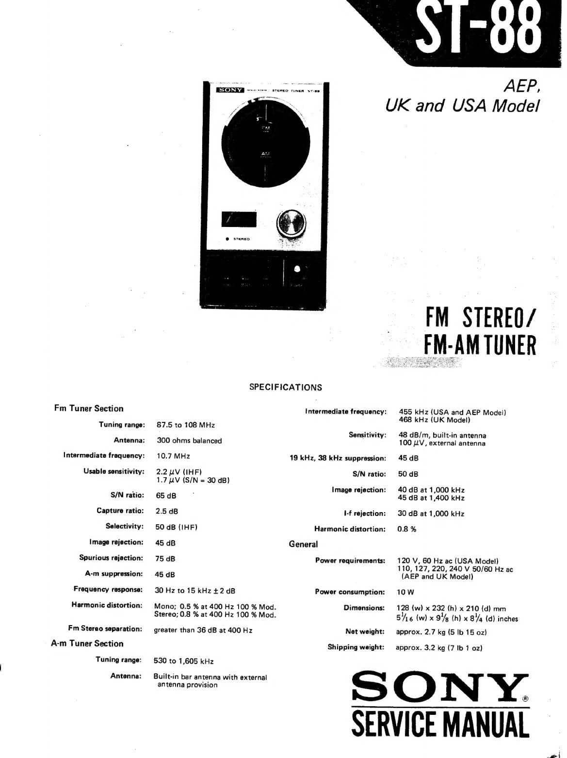
Sony ST-88 User manual

Fm
Tuner
Section
Tuning
range:
Antenna:
Intermediate
frequency:
Usable
sensitivity:
S/N
ratio:
Capture
ratio:
Selectivity:
Image
rejection:
Spurious
rejection:
A-m
suppression:
Frequency
response:
Harmonic
distortion:
Fm
Stereo
separation:
A-m
Tuner
Section
Tuning
range:
Antenna:
*.
STEREO
TUNEN
$T-80
Lf
enn,
SPECIFICATIONS
87.5
to
108
MHz
300
ohms
balanced
10.7
MHz
2.2
LV
(IHF)
1.7
LV
(S/N
=
30
dB)
65
dB
2.5
dB
50
dB
(IHF)
45
dB
75
dB
45
dB
30
Hz
to
15
kHz
+2
dB
Mono;
0.5
%
at
400
Hz
100
%
Mod.
Stereo;
0.8
%
at
400
Hz
100
%
Mod.
greater
than
36
dB
at
400
Hz
530
to
1,605
kHz
Built-in
bar
antenna
with
external
antenna
provision
Intermediate
frequency:
Sensitivity:
19
kHz,
38
kHz
suppression:
S/N
ratio:
Image
rejection:
\-f
rejection:
Harmonic
distortion:
General
Power
requirements:
Power
consumption:
Dimensions:
Net
weight:
Shipping
weight:
AEP,
UK
and
USA
Model
FM
STEREO/
FM-AM
TUNER
455
kHz
(USA
and
AEP
Model)
468
kHz
(UK
Model)
48
dB/m,
built-in
antenna
100
LV,
external
antenna
45
dB
50
dB
40
dB
at
1,000
kHz
45 dB
at
1,400
kHz
30
dB
at
1,000
kHz
0.8
%
120
V,
60
Hz
ac
(USA
Model)
110,
127,
220,
240
V
50/60
Hz
ac
(AEP
and
UK
Model)
10W
128
(w)
x
232
(h)
x
210
(d)
mm
516
(w)
x
94g
(h)
x
8%
(d)
inches
approx.
2.7
kg
(5
Ib
15
oz)
approx.
3.2
kg
(7
Ib
1
oz)
SONY.
SERVICE
MANUAL
pte

Section
TABLE
OF
CONTENTS
Title
Page
TECHNICAL
DESCRIPTION
1-1.
Block
Diagram
2...
2
ee
eee
\
DISASSEMBLY
AND
REPLACEMENT
2-1.
Wooden
Case
Removal...
2-2
eee
eet
ets
2
9-2.
Front
Panel
Removal...
2...
eee
ee
ere
ts
2
9-3.
Front
Subchassis
Removal...
2.
eee
eee
ts
2
2-4.
Fm
(A-m)
Front-End/I-f
Amp/MPX
and
Preamplifier
Board
Removal...
.-
ee
eee
ett
te
3
7-5.
Power
Supply
Board
Removal
....--
eee
setts
3
9.6.
Dial
Cord
Restringing
©...
eee
et
3
9-7.
DialLamp
Replacement
...-.
0
eee
rete
ttre
4
2-8.
Tuner
Input
Meter
Replacement...
--
+--+
eee
eet
tt
4
2-9,
Band,
Mode,
Afc
and
Power
Switch
Replacement
...--
+--+
--:
4
9-10.
Chassis
Layout...
2.
ee
ee
5
ALIGNMENT
AND
ADJUSTMENT
3-1.
Fm
I-f
and
Discriminator
Alignment
....-
+--+
eee
rrrrcs
6
3-2.
Fm
Frequency
Coverage
and
Tracking
Alignment
.....----:5
7
3-3.
Fm
Stereo
Separation
Adjustment...
6.
-
eee
te
tts
8
3-4,
A-mI-f
Strip
Alignment
..
2...
-
ee
ee
ree
ts
9
3-5.
A-m
Frequency
Coverage
and
Tracking
Alignment
.....--+---
9
REPACKING......--
+++
ee e5
ee
en
ee
11
DIAGRAMS
5-1.
Mounting
Diagram
—
Power
Supply
and
Attenuator
Boards
.....
-
13
5-2.
Mounting
Diagram
—
Fm
(A-m)
Front-End/I-f
Amp/MPX
and
Preamplifier
Board...
.-
+--+
eee
rrr
tts
14
5-3,
SchematicDiagram....----
eee
eee
ett
15
EXPLODED
VIEWS...
...----
0s
etree
teers
17
ELECTRICAL
PARTS
LIST
.....---
22s
ee
errr
19
(Ooty

SECTION
1
TECHNICAL
DESCRIPTION
BLOCK
DIAGRAM
1-1.
Cc
YILIW
LNdNI
¥YINAL
0229
“10Z7
dV¥L
VIS
cota
‘toza
LIQ
OILVY
MS
aNVa
1088
Q
wy
?
‘e)
S0ca
130
wy
wd
(zosr)
TWNINY
IL
LNdLNO
ees
HOIH
O
HI
L__
qewwon
O
far
re
O
HO-7
L_
HOIH
O
v0SD
dWVIud
Z0S0
1050
IONVIEd
JWV
Id
YIWYOISNV
EL
YIMOd
co¢a
“toZa
YsIIHLIIY
08S
LNENI
OV
a—
MS
YIMOd
4081
+9Wi
+98
Ww
L081d
(Z08s)
£050
dWVaud
0.
ie
MS:
GON
MS
6
|
dw
o74z1s|
"060
a
L0E7
7
Z0ED
AWYV
ZH
8E
SNVUL
ONIHILIMS
783
18NOG
7H
GE
voea
~
LOEa
10¢0
i
280
wv
‘9020
EDEN?
yaXIW
WY
HOOT
40€0
dwy
2H
GL
jeutuse
{
euualuy

SECTION
2
DISASSEMBLY
AND
REPLACEMENT
Note:
All
screws
in
this
service
manual
are
Phillips
type
(cross
recess),
unless
other-
wise
specified.
(—):
slotted
head
2-1.
WOODEN
CASE
REMOVAL
1.
Remove
the
four
screws
(P
4
x
16)
securing
the
wooden
case
to
the
chassis
along
with
the
rubber
feet.
2.
Remove
the
two
screws
as
shown
in
Fig.
2-1.
mee
ANT
;
|
au
GRouaD
[Ts00s
B
.
Fj
ey
ok
.
)
:
:
Be
x8
|
~
sy
Fig.
2-1.
Wooden
case
removal
;
ae
D
hee
ie
a
j
y
~
|
ats
2-2.
FRONT
PANEL
REMOVAL
1.
Remove
the
wooden
case
as
described
in
Procedure
2-1.
2.
Pull
out
the
tuning
knob.
3.
Remove
the
four
screws
securing
the
front
panel
to
the
chassis
as
shown
in
Fig.
2-2.
4.
Remove
the
front
panel
in
the
arrow
direction
shown
in
Fig.
2-3.
5.
Unsolder
the
two
lead
wires
from
the
TUNER
INPUT
meter
and
pull
out
the
lamp
socket
from
the
TUNER
INPUT
meter
bracket
as
shown
in
Fig.
2-3.
2-3.
FRONT
SUBCHASSIS
REMOVAL
1.
Remove
the
wooden
case
and
the
front
panel
as
described
in
Procedures
2-1
and
2-2.
2.
Remove
the
nine
screws
(
(A)
)
as
shown
in
Fig.
2-4
and
Fig.
2-5.
3.
Pull
off
the
STEREO
lamp
from
the
grommet.
;
Fig.
2-4.
Front
subchassis
removal
oo

«oy
Fig.
2-5.
Front
subchassis
removal
(2)
2-4.
FM
(A-M)
FRONT-END/I-F
AMP/MPX
AND
PREAMPLIFIER
BOARD
REMOVAL
1.
Remove
the
wooden
case
as
described
in
Procedure
2-1.
2.
Unsolder
the
ribbon
antenna
at
the
fm
(a-m)
front-
end/i-f
amp/MPX
and
preamplifier
board
as
shown
in
Fig.
2-6.
3.
Remove
the
rear
panel
in
the
arrow
direction
by
loosening
the
three
screws
(
©
)
as
shown
in
Fig.
2-6.
4.
Loosen
the
two
screws
(
®))
as
shown
in
Fig,
2-4,
antenna,
NX
=
\
fm
(a-m)
front-end/
|
i-f
amp/MPX
and
_”
preamplifier
board
Fig.
2-6.
Fm
(a-m)
front-end/j-f
amp/MPX
and
preamplifier
board
removal
5.
6.
Remove
the
two
screws
(B))
as
shown
in
Fig.
2-5.
Carefully
remove
the
board
from
the
chassis
taking
care
not
to
break
the
lead
wires.
2-5.
POWER
SUPPLY
BOARD
REMOVAL
1.
Remove
the
wooden
case
as
described
in
Procedure
2-1.
.
Unsolder
the
three
lead
wires
(red,
white
and
black)
connecting
the
power
supply
board
and
the
fm
(a-m)
front-end/i-f
amp/MPX
and
preamplifier
board.
.
Unsolder
the
ribbon
antenna
as
shown
in
Fig.
2-6.
-
Loosen
the
three
screws
(
©)
as
shown
in
Fig.
2-6.
.
Carefully
open
the
rear
panel
in
the
arrow
direction
shown
in
Fig.
2-6
taking
care
not
to
break
the
lead
wires,
.
Remove
the
two
screws
(B
3
x
5)
securing
the
power
supply
board.
2-6.
DIAL
CORD
RESTRINGING
1,
10.
11.
Remove
the
wooden
case,
front
panel
and
front
subchassis
as
described
in
Procedures
2-1,
2-2
and
2-3.
.
Make
a
loop
of
the
dial
cord
as
shown
in
Fig.
2-7.
.
Make
a
knot
and
hook
a
spring
to.
the
dial
cord
and
then
fasten
the
knot
as
shown
in
Fig.
2-8.
.
Loosen
the
two
screws
securing
the
dial
scale
ass’y
to
the
tuning
drum
shaft
and
remove
the
dial
scale
ass’y.
-
Hook
the
spring
to
the tab
on
the
dial
scale
ass’y
and
string
the
dial
cord
around
the
dial
scale
ass’y
and
the
tuning
shaft
in
numerical
order
as
shown
in
Fig.
2-9
and
2-10.
.
Install
the
dial
scale
ass’y
to
the
tuning
drum
shaft
and
fix
a
dial
scale
set
screw
temporarily.
.
Set
the
AFC
switch
to
OFF.
.
Tune
the
set
to
the
local
fm
station
by
turning
the
tuning
shaft.
Loosen
the
dial
scale
set
screw
and
turn
the
dial
scale
ass’y
to
the
position
where
the
fm
pointer
on
the
dial
front
glass
indicates
the
local
fm
station’s
carrier
frequency.
Fix
the
two
dial
scale
set
screws.
Make
sure
that
the
correct
dial
calibration
is
also
done
at
a-m
mode.

dial
cord
317
mm
(1242)
hot
0.3
mm
(
Yea)
dia.
Fig.
2-7.
Dial
cord
2
the
dial
cord.
Fig.
2-8.
Finish
point
of
dial
cord
dial
cord
dial
scale
ass‘y
!
|
yvatt
two
turns
Fig.
2-10.
Dial
cord
restringing
(Front
View)
2-7.
DIAL
LAMP
REPLACEMENT
1.
Remove
the
wooden
case
and
front
panel
as
described
in
Procedures
2-1
and
2-2.
.
Slide
the
lamp
socket
forward
to
permit
removal
of
lamp
as
shown
in
Fig.
2-11.
.
Unscrew
the
lamp
from
the
socket
and
install
a
new
one
and
push
the
socket
back
to
its
original
place.
Fig.
2-11.
Dial
lamp
removal
2-8.
TUNER
INPUT
METER
REPLACEMENT
1.
Remove
the
wooden
case
and
front
panel
as
described
in
Procedures
2-1
and
2-2.
.
Unsolder
the
two
lead
wires
and
remove
the
two
screws
as
shown
in
Fig.
2-12.
.
Install
a
new
one.
2-9.
BAND,
MODE,
AFC
AND
POWER
-
WwW
SWITCH
REPLACEMENT
.
Remove
the
wooden
case
and
front
panel
as
described
in
Procedures
2-1
and
2-2.
.
Remove
the
two
screws
securing
each
switch
to
the
chassis
as
shown
in
Fig.
2-13.
.
Unsolder
the
switch
lead
wires.
Install
a
new
one.
_)

B3x
6,
self-tapping
TUNER
INPUT
meter
B3x6é
self-tapping
TUNER
INPUT
"Q
Of
meter
eile
Fig.
2-12.
Tuner
input
meter
replacement
Fig.
2-13.
BAND,
MODE,
AFC
and
POWER
switch
replacement
2-10.
CHASSIS
LAYOUT
a-m
bar
antenna
fm
(a-m]
front-end/i-f
amp/MPX
attenuator
and
preamplifier
board
board
power
supply
board
power
transformer
Fig.
2-14.
Chassis
layout

SECTION
3
ALIGNMENT
AND
ADJUSTMENT
3-1.
FM
I-F
AND
DISCRIMINATOR
Simel
oorerster
menos
«
ALIGNMENT
:
;
S
Test
Equipment
Required
CAUTION
1,
Signal
generator
capable
of
generating
a
10.7
MHz
The
ceramic
filters
in
the
fm
i-f
circuit
are
a-m/fm
signal.
selected
according
to
their
specified
center
fre-
quencies
and
color
coded
as
shown
in
Fig.
3-1
2.
Oscilloscope
and
listed
in
Table
3-1.
Check
the
color
code
of
Vertical
sensitivity
100
mV/cm
minimum
the
filters
to
identify
the
same
center
frequency
nae
when
replacing
any
of
these
filters.
3.
Ac
VIVM
4.
Alignment
tools
TABLE
3-1.
FM
I-F
CERAMIC
FILTERS
Preparation:
Part
No.
Color
Specified
Center
Freq.
1.
Connect
the
input
cable
of
the
oscilloscope
with
Higator
cli
-
ees
sana
ie
10.70
MHz
alligator
clips
to
R229
and
ground
on
the
fm
(a-m)
front-end/i-f
amp/MPX
and
preamplifier
board,
and
ESgeaeee!
pits
sp
tetales
solder
a
0.02
uF
capacitor
across
these
clips
as
'/.
1-527-220-3
1
orange
10.73
MHz
aye
Fi
P P
;
1-527-220-41
black
10.64
MHz
ai
Re:
1-527-220-51
white
10.76
MHz
2.
Connect
the
output
cable
of
the
generator
across
CV102
on
the
fm
(a-m)
front-end/i-f
amp/MPX
and
preamplifier
board
through
a
0.02
uF
coupling
.
capacitor
as
shown
in
Fi
color
dot
a
BPR
5
AMES
AER
Fig.
3-1.
Color
dot
on
ceramic
filter
y
;
€
iz)
02
uF
S%
‘er
fzas
R2
Rel
a-M
osc
trimmer
Fig.
3-2.
Interruption
of
fm
or
a-m
local
oscillator
operation
Note:
Local
oscillator
should
be
killed
when
performing
this
alignment.
To
stop
the
local
oscillator
operation,
shunt
the
oscil-
lator
capacitor
with
a
0.02
UF
capacitor
as
shown
in
Fig.
3-2.
To
rf
signal
{
generator
Fig.
3-4.
10.7-MHz
signal
injection

Procedure:
1.
With
the
equipment
connected
as
shown
in
Fig.
3-5,
set
the
signal-generator
controls
as
follows:
Frequency........
Specified
frequency
of
ceramic
filter.
See
Table
3-1.
Modulation
.......
Fm,
400
Hz,
100
%
(75
kHz)
Output
level.......
1,000
nV
(60
dB)
2.
Set the
tuner
switches
as
follows:
BAND
switch......
FM
MODE
switch......
MONO
AFC
switch
.......
OFF
3.
Adjust
the
signal
generator
frequency
slightly
to
obtain
a
maximum
output,
and
then
change
the
signal
generator
modulation
to
a-m,
400
Hz
30
%.
4.
If
the
discriminator
transformer
IFT201
is
not
aligned
correctly,
400
Hz
ripple
will
be
observed
as
shown
in
Fig.
3-6.
5.
Turn
the
secondary
side
core
(green)
of
discrimina-
tor
transformer
IFT201
(see
Fig.
3-10)
with
an
alignment
tool
to
obtain
a
minimum
indication
on
the
oscilloscope
as
shown
in
Fig.
3-6.
Fig.
3-6.
Fm
discriminator
alignment
output
response
Note:
Turn
the
core
carefully
and
slowly
because
the
output
appearing
on
the
oscilloscope
jumps
up
and
down
when
turning
the
core.
This
might
cause
diffi-
culty
in
determining
the
point
of
mini-
mum
output.
Also,
at
both
extreme
positions
of
the
top
core,
decreased
out-
put
will
be
observed.
The
real
null
point
should
be
obtained
in
the
middle
of
the
rf
eae
signal
Cv102
generator
=
OQ-—-__~__—____—__.
R229
|
core
thread
length,
and
maximum
output
occurs
at
each
side
of
the
true
null
point.
6.
Change
the
signal
generator
modulation
to
fm,
400
Hz
100
%.
7.
Turn
the
core
of
fm
IFT101
and
primary
side
core
(brown)
of
discriminator
transformer
IFT201
(see
Fig.
3-10)
to
obtain
the
maximum
output.
3-2.
FM
FREQUENCY
COVERAGE
AND
TRACKING
ALIGNMENT
Note:
Before
starting
this
alignment,
the
fm
i-f
and
discriminator
alignment
should
be
performed.
Test
Equipment
Required
1.
Fm
signal
generator
2.
Ac
VTVM
3.
Oscilloscope
4.
Alignment
tools
Preparation:
1.
Connect
the
equipment
as
shown
in
Fig.
3-7.
2.
Set
the
tuner
switches
as
follows:
BAND
switch...
...
FM
MODE
switch.
.....
MONO
AFC
switch...
2...
OFF
Signal
Generator
Method
Follow
the
procedures
given
in
Table
3-2
when
performing
this
alignment
with
an
fm
signal
generator.
Be
sure
that
the
dial
is
mechanically
calibrated.
Off-the-Air
Signal
Method
Accurate
dial
calibration,
and
a
frequency
cover-
age
test
can
also
be
performed
by
utilizing
off-the-air
local
fm
signals.
However,
before
performing
the
following
procedure,
be
sure
that
the
dial
is
mechani-
cally
calibrated.
oscilloscope
PAA
Fig.
3-5.
Fmi-f
and
discriminator
alignment
test
setup
by
rf
signal
generator

ST-88
ac
VTVM
oscilloscope
fm
oO
——“-"—
0
—
0
signal
ANTENNA
NORMAL
OUTPUT
IN
ma
er
generator
©
Jack
(J802)
Lo
Fig.
3-7.
Fm
frequency
coverage
and
tracking
alignment
test
setup
TABLE
3-2.
FM
FREQUENCY
COVERAGE
AND
TRACKING
ALIGNMENT
SG
Coupling.....
re
SG
Output
Level
..
400
Hz,
100
%
mod;
as
low
as
possible
Step
SG
Frequency
Dial
Indication
Ac
VTVM
Adjust
Indication
Connection
87.5
MHz
87.5
MHz
NORMAL
OSC
coil
L103
Maximum
OUTPUT
See
Fig.
3-10.
VTIVM
2
108
MHz
108
MHz
jack
(J802)
FREQUENCY
COVERAGE
ALIGNMENT
reading
OSC
trimmer
CT103
See
Fig.
3-10.
SG
Coupling.....
Direct
SG
Output
Level
..
400
Hz,
100
%
mod;
as
low
as
possible
~~
TRACKING
ALIGNMENT
87.5
MHz
87.5
MHz
NORMAL
OUTPUT
jack
(J802)
108
MHz
108
MHz
3-3.
FM
STEREO
SEPARATION
ADJUSTMENT
Maximum
VTVM
reading
Antenna
coil
L101
RF
coil
L102
See
Fig.
3-10.
Antenna
trimmer
CT101
RF
trimmer
CT102
See
Fig.
3-10.
Procedure:
1.
Precisely
tune
the
set
to
the
carrier
frequency
of
stereo
signal
generator,
then
turn
the
top
core
of
switching
transformer
L301
(see
Fig.
3-10)
to
obtain
maximum
output
at
the
left
channel.
Note
that
this
adjustment
has
a
close
relationship
with
stereo
distortion.
Test
Equipment
Required
1,
Fm
stereo
signal
generator
2.
Ac
VTVM
3.
Oscilloscope
2.
Record
the
output
level
of
the
left
channel
when
the
stereo
signal
generator
input
selector
is
set
to
the
left
channel.
Preparation:
1.
Remove
the
wooden
case
as
described
in
Procedure
2-1
on
page
2.
k
: ;
a
3.
Switch
the
stereo
signal
generator
input
selector
.
Connect
the
test
equipment
as
shown
in
Fig.
3-8,
then
set
the
fm
stereo
signal
generator
controls
as
follows:
Carrier
frequency
...
98
MHz
Output
level.......-
1,000
nV
(60
dB)
Mode
........-.--
Stereo
Audio
(400
Hz)
Mod
.
67.5
kHz
(90
%)
Pilot
(19
kHz)
Mod...
7.5
kHz
(10
%)
Note:
75
kHz
(100
%)
if
the
metering
indicates
total
modulation
(audio-pilot).
to
the
right
channel
and
read
the
residual
signal
level
in
the
left
channel.
.
The
output-level
to
residual-level
ratio
represents
the
separation.
Adjust
separation
adj.
control
RV501
(see
Fig.
3-10)
for
minimum
residual
level.
Check
the
right
channel
for
separation.
Usually,
about
an
8
to
9
dB
difference
in
channel
separation
exists.
Readjust
RV501
for
minimum
difference
between
left-
and
right-channel
separation.
While
Ww
r

ST-88
ac
VTVM
oscilloscope
NORMAL
OUTPUT
jack
(J802)}
fm
stereo
signal
generator
Fig..3-8.
Fim
stereo
separation
adjustment
test
setup
doing
this,
remember
that
the
output
level
also
changes
according
to
the
setting
of
RVS5O1.
3-4.
A-M
I-F
STRIP
ALIGNMENT
Note:
The
a-m
i-f
transformers
(CFU201
and
IFT202)
are
shipped
from
the
factory
with
all
adjustments
set
for
correct
opera-
tion.
Therefore
no
adjustment
is
required
Procedure:
in
field
service.
2.
Loop
antenna
3.
Ac
VTVM
or
oscilloscope
With
the
equipment
connected
as
shown
in
3-5.
A-M
FREQUENCY
COVERAGE
AND
Fig.
3-9,
follow
the
procedures
given
in
Table
3-3
TRACKING
ALIGNMENT
when
performing
this
alignment
with
an
a-m
signal
generator.
Preparation:
Off-the-Air
Signal
Method
Set
BAND
switch
to
AM.
Accurate
dial
calibration,
and
a
frequency-
Signal
Generator
Method
coverage
and
tracking
test
can
also
be
performed
by
utilizing
off-the-air
local
a-m
signals.
However,
before
Test
Equipment
Required
performing
the
following
procedure,
be
sure
that
the
:
dial
is
mechanically
calibrated.
1.
Signal
generator
loop
;
7
antenna
oscilloscope
NORMAL
am
OUTPUT
signal
jack
|
|
IN
generator
(J802)
re
O
|
O
ey
is
Fig.
3-9.
A-m
frequency
coverage
and
tracking
alignment
test
setup

TABLE
3-3.
AAM
FREQUENCY
COVERAGE
AND
TRACKING
ALIGNMENT
SG
Coupling.....
Loop
antenna
ss
FREQUENCY
COVERAGE
ALIGNMENT
SG
Output
Level
..
400
Hz,
30
%
mod;
as
low
as
possible
Step
SG
Frequency
Dial
indication
Ac
VTVM
Adjust
Indication
Connection
1
550
kHz
550
kHz
NORMAL
OSC
coil
L402
Maximum
OUTPUT
See
Fig.
3-10.
VTVM
2
1,600
kHz
jack
ee)
OSC
trimmer
CT402
eagine
See
Fig.
3-10.
SG
Coupling.....
Loop
antenna
Nie
TRACKING
ALIGNMENT
SG
Output
Level
..
400
Hz,
30
%
mod;
as
low
as
possible
1,600
kHz
600
kHz
NORMAL
Position
of
bar
antenna
Maximum
OUTPUT
L401
VTVM
1,400
kHz
Antenna
trimmer
CT401
See
Fig.
3-10.
jack
(J802)
reading
Adjustment
Parts
Location:
Tune
to
the
SG
signal.
fm
1FT101
fm
osc
coil
fm
ré
coil
fm
ant
coil
L103.
on
on
CT4
01
fm
osc
trimmer
CT103
fm
rf
trimmer
fm
ant
trimmer
CT102
CT101
Y
@m
osc
coil
L402
discriminator
transformer
T201
primary
side
(orewa)
secondary
side
switching
transformer
(green)
L301
.
separation
adj.
RV501
Fig.
3-10.
Adjustment
parts
location
—~10—
ro

SECTION
4
Note:
AEP
Model
(Serial
No.
900,001
and
later)
REPACKING
UK
Model
(Serial
No.
400,001
and
later)
USA
Model
(Serial
No.
800,001
and
later)
The
original
shipping
carton
and
packing
set
must
be
repacked
in
these
materials
precisely
materials
are
the
ideal
containers
for
shipping
the
unit.
as
before.
The
proper
repacking
procedures
are
However
to
secure
the
maximum
protection,
the
shown
in
Fig.
4-1,
X-44900-02-0
Polishing
cloth
ass’y
X-37010-29-0
(USA‘Modsl.onty):
©
seta
cscs
tbs
sce
cote
Daas
cavacesaberebeneatantbecbeeecanctcCteS
ss
aeabiseSccendenstnmeshasaasaussbvsee
obetetaecas
lus
tccuiceteSteescoadeaadl
tacediecnearsacishuniit
3-780-193-11
(AEP
Model)
card
ass’y,
warranty
3-780-193-21
{USA
Model}
RN
lade
aks
me
it
|
Waadecbedaae
lau
Teh
caaclen
tage
eaguhalehyeitodin
Manseted
artless
toseenaarinsonataarssdectucdllbeeelea
dh
setahales
3-780-193-81
(UK
Model)
Manual,
instruction
3-793-520-00
(UK
Model
only}
card,
warranty
1-534-049-31
cord,
connection
1-§01-083-21
ribbon
antenna,
fm
3-793-610-00
schematic
diagram
1-5§34-819-00
(UK
Model
only)
cord,
power
4-820-425-00
cushion,
side
fright)
3-701-020-00
bag,
polyethylene
3-826-155-00
bag,
polyethylene
4-820-425-00
cushion,
side
{left}
FEZ6B8SFOO.
ai
acidtals
tts
el
i
sauisddesSodcsegev'sed
cea
sesisecaststaehsonechsansdecyacaaed
yaseaugssstbelvestasleshcuyebeueteoisuy
cgvedyaedaics
acsudeiwsus
ncaucassdbessgsaee
sascusesactupcansatoassebesantbedescattassines
carton,
individual
4-826-834-00
carton,
master;
4
sets
3-701-396-00
{UK
Model
only}
label,
power
cord
Fig.
4-1.
Repacking
—ll-
—~12—

SECTION
5
Note:
AEP
Model
(Serial
No.
900,001
and
later)
|
UK
Model
(Serial
No.
400,001
and
later)
DIAGRAMS
USA
Model
(Sera!
No.
800,001
and
later)
5-1.
MOUNTING
DIAGRAM
—
Power
Supply
and
Attenuator
Boards
—
—
Conductor
Side
—
[Power
Supply
Board]
AEP
and
UK
Model
|
F704
|
100maT
‘
.
$
BLU
1
<
Ta
power
transformer
sang
RED
:
:
wEiied
£64
To
power
trensformar
|
be:
Mises
lag
anal
:
WHT
18}
c
;
To
POWER
SW
(S804)
kK)
mM
i
atx
:
é
100maAT
baa
/}
To
power
transformer
EO
—__o
ABN
ps
F702
F701
}
eac
oy
s
200mAT
500maT
28C1124
i
|
;
WHT.
O70]
c706
:
Ga
pe
as
To
voltage
selector
"1002
pety
:
:
us
To
ground,
lug
terminal
on
chassis
2)
Lf
hoz
Oo
7,
So3s
R702
I
100V
i
7
1,5k
;
RED
“i
sale
>
ae
om
To
fim/am
front-end/i-t
am
H
0703
C702
eee
MPX
and
preamplifier
board,
R232
ave
IT243
0.001
16V
10D2
a
af
C704
R703
wa
16V
R70!
war
=
35V
1.2k
a
om
o———
=
To
fm/a-m
front-end/i-f
amp/
To
ground,
lug
terminal
on
chassis
fe
16.6V
i
;
MPX
and
preamplifier
board,
R313
4
f
e703
at
en
i.
19
Tak
33
2SC1124
oe
To
fm/a-m
Front-end/i-f
amp/
*
To
power
transformer.
SKE,
re
25
neh
ov
5
MPX
and
preamplifier
boerd,
.
7
. :
ground
anode
cathode
:
1T243M
[14]
USA
Model
BLU
To
power
transformer
To
power
transformer
EO
t
|
say
acide
RCP
ORG
To
power
transformer
BLK
<
:
Tene
ene
*
:
i
.
ot
To
power
transformer
2)
—__-___-_~_-_—»
a
;
F702
te
3
tad
250mAT
a
“0
4
i
}
|
i
4
Be
ae
Ee
To
power
SW
(S804)
|
:
;
nt
ground,
lug
terminal
on
chassis
20,
R792
ayes
‘
——
ws
es
cy
RED
1
tele
front-end/-f
amp/
ara
0703
c702
at
MPX
and
praamplitier
board,
A232
|
17243m
1.0.00)
|
ev
aio.
‘R701
ee
.
et
WHT
To
frn/a-m
front-end/i-t
amp/
ae
4 ;
MPX
and
preamplifier
board,
A313
To
ground,
lug
terminal
on
chassis
16.6V
ee
A
j
3
€703
Q701Y
23V
-
er
701
:
ni
ascliza
=
oe.
eB
1
tle
front-endsit
arnp/
aay.
;
MPX
and
preamplifier
bosrd,
ground
[Attenuator
Board]
To
fm/a-m:
front-and/i-f
amo/
MPX
and
preamplifier
board.
:
€507,
C508
i
/—13-

5-2.
MOUNTING
DIAGRAM
—
Fm
(A-m)
Front-End/!-F
Amp/MPX
and
Preamplifier
Board
—
—
Conductor
Side
—
Bor
Antenna
Transistors
and
Adjustment
Parts
Location
401
ono
—w
:
;
R204
56
R206
1k
_»=CY
Rose
22
ANTENNA
0
eae
204
saw
288,
Tae
mas
2n
a2
‘
Q202
|
r
=
0
Te
tomtgn
eee
ce
|
105}.
gt
|i
oops
SF
ly
Bee
tyes
oy
Ra
IFT10t
2200p
|
'
n202_
4
eer
ag
Me
-—}
R202
af
87
RIOT
Toro
te
a
a
Tizee
R208
1.5k
T
;
|
220
iia
6.2V
0102
Or
gio
zsc4030
oa
206
Sat
10v,
RIO9
300
gc
}03C
L103
Lid2
Q103
Qio1
Q203
CTiO1
CT40I
CT102
CT402
WHT.
|
To
BANO
SW
(S801)
eee
io
0.0:
||
sagt
Pere
c4c2
3
STEREO
lomp\WHT/GRN
0.01
i
Vv
¢
‘
ed
A
eee
!
R313
15k
To
power
supply
wut
I
ono
i
board,
R701
To
attenuator
board,
owyr-8
k
2
rsog,!
R503
120k
R506
120k
tov
i
C50!
nev
.
33/25V
ofan
ev
Pgs
0.6V
Q501
Q503
2SC632A
“10¥”""
D3
01sD504
|
ele
{T22A
BRN
To
MODE
Sw
(S802)
To
MODE
SW
(S802)
—GeN_/
To
BANO
SW
(S801)
—»——-244_/
To
power
supply
board,
R701
OW
ec:
qo
j-e
$6G
oO
gs
o
ace
2SK23A
28K42
ee
28¢710
181555
2SC633A
1SSBIM
2SC632A
2SC634A
—14—
0208,0209
R505.
ose
Ss,
0
0.
us
olsv
2SC632A
aa
bey
i
Taste,
ie
-
.
Lege
ve
T
Pe
is
awit
ae
TR
Patt
oat
Rano
Hi
PP
DIOt
Moos
“Co?
*osaa
ce
are
1103
mos
a
2
fae
gd
20
ss
181555
R304
47k
Oo.
Te
{h°
oh
HF
4./25N
R305,
tke
f°
Q301
RWe2
82k
2SCE33A
2303
22x
OW
or
47/25N
(
Path
WHT
BOT,
A604
iS
1g
Segg
oo)
eeoocoa
D205
1T22A
pe
1
R223
206
1T22A
F560
LG
restage
Fie
C226
ee
40
fT
To.0z2
am
bf
a2k’
t
R29
G.Bk
oe
eee
R236
27k
pee
ww
mm
cFU20T
1SVq
R242
68k
R218
tie
R217
09
—_wy+-——-0
3.9V
220
C206
06
9002
Fe
phys’
grav
eee
ae
:
Bev
BSCTO
233
peed
re
er
oF
8220
F220_,,2:2k
4
Vo
isv
470p
=
22p'
“47k
D201
@D202
IT22AF1T22A
C234
BLK
To
BAND
SW
(S801)
To
BAND
SW
(S801)
Note:
Audio
signals
are
expressed
C224.4.7/25)
o—{r-~
<
ony
é
?
To
AFC
SW
(S803)
«
WHT/BLK_
To
TUNER
INPUT
meter
(M201)
Q
To
BAND
SW
($801)
To
ground,
power
supply
board
To
TUNER
INPUT
meter
(M201)
@
in
“dB”
referred
to
{
0.775
V(0
dB)
400
Hz,
receiving
fm
rf
signal
of
98
MHz
{1000
pV
(60
dB),
75
kHz
(100
%)
Mod.
).
[
]:
(..
dB
):
stereo
operation

5-3.
SCHEMATIC
DIAGRAM
FM(A-m)
Front-End/IF
Amp
/MPX
and
é
2
Xs
a
ye
Sa
ae
Se
QiOl
25K42
102
2SK234
Q201,Q202
2S¢403C
Q203
2SC710
Q204
2SC7!0
Q205
2$¢403¢
0201,0202
iT22A
(FM
RF
AMP)
(FM
MIXER)
{EM
EF
AMP}
(FM
i-F
AMP)
0208,
0209
IFMACM
FF
AM)
(EM/M
PF
AMP)
£120
p29)
S820,
aev
181555
ig
eRe
NOT
@202
22083
”
g
51
Q102
av
IFT
Iot
ie
6239
:
if
‘al
jc2!?
uv
mo
—4
$20!
“4
=
a0
8
i?
=e)
Ti
Fo
8)
5
!
I
\
=
OE
NS
5
1
6}
sf
*
1
[Go
_toege
nnn
af==
"sea
240p
iS
2
=
1
Nile:
Lbg------
R229
470
mie
8
c2te
71348
0000
CF
202]
120
(-20¢8}
Ql03
2sc7io
(FM
OSC}
iP
801
8
ANTENNA
w.
TERMINAL
5
S
Power
Supply
Board
=
~
~AEE
and
UK
Mode:
1
Q70t
D701,D702
2scil24
lo02
a
oe
are
tata
|
woe
ee
ee
0703
0704
1T243M
=:
IT243M
Preamplifier
Board
pa
ob
Re
R36
cy4
XK
=
S88
‘or
Bike
=
«
@
:
17-22
3
[2s
abiigesv
3
ET
wh
fel
Fee
bod
503
OS
BT
Sis
=
474
RBI
a7v
(ov)
+2246
(-28dB)
Tea
Ta
ed
Le---__
e
-
-
d
g
a
=
2
R248
0207
4
910
ISI555
>
Q501,9503
Q502,
9504
tev
2SC632A
csos
2SC634A
5
{PRE
AMP)
(OOp
(PREAMP)
-——T7
4
=
sez
ay
LT)
tase
2648
|
6592
«120k
510
leig”
NF
33k.
(-3008)
TH
O8Y
“>
yee)
509
-16—
10
ON
$803
}
>
OFF
AFC
SW
TUNER
INPUT
-+8dB
j
(+5,6d8)
1802
OUTPUT
5
sR608
He
TMINAL
€O)
HIGH
a
ag
vat
:
sisP
©)normay
oe
a
fo)
HGH
—
Attenuator
Board
Ref,
No.
Description
Position
$801
BAND
SW
FM
(FM-AM)
$802
MODE
SW
STEREO
{STEREO-MONO)
$803
AFC
SW
ON
(ON-OFF)
$804
POWER
SW
OFF
(ON-OFF)
Note:
All
resistance
values
are
in
ohms.
k
=
1,000
M
=
1,000k.
All
capacitance
values
are
in
UF
except
as
indicated
with
p,
which
means
MMF.
All
voltages
are
dc
measured
with
a
VOM
having
20
k
ohms/volt
input
impedance.
No
signal
in,
Voltage
variations
may
be
noted
due
to
normal
production
tolerances.
Audio
signals
are
expressed
in
“dB”
referred
to
0.775
V
(0
dB)
400
Hz,
receiving
fm
rf
signal
of
98
MHz
[1,000
LV
(60
dB),
75
kHz
(100
%)
Mod.}.
t
1?
(..
dB
):
%&:
C315
and
C316
are
for
USA
Model
only
Capacitors
marked
A
are
built
in
each
transformer.
stereo
operation

recess
type)
unless
otherwise
indi-
Note:
All
screws
are
Phillips
type
(cross
cated.
(—):
slotted
head
SECTION
6
EXPLODED
VIEWS
(1)
Note:
AEP
Model
(Serial
No.
900,001
and
later)
UK
Model
|
(Serial
No.
400,001
and
later)
:
OE
20)
20UUI09
Indu}
IR
"sepjoY
deat
"jaued
(Ajuo
japow
NN)
yisea
‘uonnes
‘(g)
1998!
O00-S6E-10L-E
—
8xea
10-8b5-Z89-L
{Ajuo
jepow
NN)
40198498
BGEI{OA
“jaqe{
00-°G89-LOLE
JaA02
10398;85
BbeIj0A
‘{g}
MB1IS
00-S90-€08
b
sojenuanre
‘pse0g
JINIHD
ayajdusoz
ee
eee
ee
9ZEEL-CEEB
jepow
NN
pue
dIV
USA
Model
(Serial
No.
800,001
and
later)
-
@-g
/jndut
98
‘s012eUu0F
NN
i
Sc}
uapoom
‘Asse
ased
O-60-8978-X
Ly
ool
‘eng
tye
ogc
‘asry
00-680°2ES-
00-620-2ES-I
vw
oag
‘asny
00-6£2-ZES-t
ay”
ne
53
=
00-22LE-L08-b
XN
00°9¢S-60S-t
yddns
samod
“pse0g
bujdder-syas
‘Gx
£ g
Neon
eee
ce
ene
ee
eet
3yN9419
ajajduslor
yuys
Jeoy
10-995-789-L
Ne
ib
9667868
a
009b0-S1Sh
%
xEG
e1p
ww
&
“nu
1OgvSc8ot
a
OO-EEO-b89L
asny
‘sepjoy
Pas
:
pi
OONKE-
LORE
2-7
(Ajue
japow
vsn}
fAiyo
pow
YSN)
Lv
O8e
ete
a“
ra
_—
gatas
upens
‘a2ejd
:
00-09%-CESt
®
EE
ies
é
00-901
-8L
8-6
.
a
eg,
eae
y=
{Auo
jepow
¥sn}
G
&<
.
-
Plog
Jano”
‘jorjas
ules
AES.
8
\
\
|
&)
(Ayuo
japow
wsn)
D”
£
‘uoneoipur
Aqzeder
asny
*jeqey.
;
16°889-
|
foe
9a-zEO0LrE
AS
—~
sr
I
|
(1epow
NN
pue
iJ
vsn}
wonnes
yaqe)
—
_b
tepew
wsn)
Aiddns
semod
i
“'gxeg
00-#96-800-4
gxemsd,
—P##0q
1uno4
apejdusoo
—H)
|
yi
i
0-999-289°Z
(oepR
eS?
ETEEL
TIER
||
Py
h
aS
@
g
0
HA
1c
-
|
Sy
.
91x
od
y
9
PX
(Ajuo
japoy
YSN,
oy
10-G91-Z89-L
A
LU
0Gz
‘uoneoipul
Ayjoedeo
asny
yn
prys-~
4
1e-eeg-toce”
=
8X
EMSd
1O-8¥6-78FL
|
ACs
uoszeaiioeds
‘jeqe]
%
(pow
xn)
4aqqns
Asse
300}
CS)
7
00-08-9286
o-60-19ter-x~
Ss
(pom
ys
&
‘a
00-208-928-6
|
repo
d3v)
TSS
90-108
928-6
(epow
ysn}
40}
9998
8B@1{OA
“19A0F
00-91r
OLE
so
est
9XxE@
a
GO-LES-Z89L
(Ajue
japow
ysn)
MAINS
‘UOHNED
‘jage}
4
00-9£9°608-b
8
AP
papi
!
Z
NYS
“19409
Pi
pa
3
108
00-SL¢-L084
407
ENE
“pse0g
*
INIID
BY9{AUu0D
6
92EEL-
TEER
d-y
‘ouoyd
“yor!
§=—
Buddet-4j0s
“9
X
E
OO-ZSE-9ES-I
1Z-G6G-SEPL
(Ajuo
fepoW
WSN)
DDI
‘1°9I
(VNNILNV)
2p
‘dpas
jeususser
00-8EZ-10LE
a
f
{y}
4ea2
‘joued
GxEg
..
:
él
Ss
OOH
eIzEY
10-966:
289-L
~
=
<
SSS
($'G
*
GE)
uojAu
ents
e
OOPEL
TIED
Q
(eippius)
ep
wit
9°Z
“1eysem
aA
GE-LOLETHL
ge
¥x978
D
(Avo
epow
Ws)
QPELLAZSL
8X
EMSd
pratys
“ore
1O-846-C89-L
00-088
928-¥
euuajue
aul
wy
‘Asse
s0329UU0D
o-fo-e9zer
xX
(Ajuo
JePOW
WSN)
49MOd
‘ps09
009
CSRES-L
ageys
Burund
‘yayoesq
O0-L78-
98
b
sozizedes
Buruny
"(g)
sea6
Jayjyduesid
puke
XdW
OO-O28
978%
/duse
j-}/pua-yuol
(us-e)
wy
*pseog
1NI49
ayajdusor
8xEg
8
a
LZEEL
TIER
10-863-289-L

«
we
rm)
erp
wus
g
‘Burs
Bujuleres
10-601
-629-L
uojAu
“sayseM
Buruny
‘Wyeys
00-621
-606-&
qayoesg
aseys
Buruny
‘aseq
9xEa
00-918-978-b
GO-LOS-789-L.
qyeys
wrup
Buruny/3zeys
jaayMAl}
“18yx9e1q
7
bujdder-j788
“9
X
EG
On.
00-028:
908-b
1Z-SbS-GEFL
@
4
x
oat
{8YIMOd)
4208]
“YOUMS
~
fe
I.
(]@POW
VSN)
00-EZO-91G-E
Nepow
3A
pue
d3V)
1F-L1E
HS
t
usoj}10gq
‘sissy?
>
eXEd—
;
One
;
OO-EL8
978
b
é
“B
aaa
nj
LP
OO-ELS
PEPE
paaymAls
e
00961-9287
|
ep
wus
¢
‘Bry
2
Q
$
a
hog
3
is)
«x
Lye)
A)
LO
(Ajuo
ey
an
eae
a
7
HULL.
ea
“jaqe;
qyeys
windup
Bujund/ajzeys
paaymdls
"29
4ICIG
:
BOE
EE
pars
.
00078:
928-b
yamod
*s9uss0jsues)
bs
|
4
:
o-ops2eod
j
SS
Roser
Wa
~
ieubaces:
5
Rr
pe
os
jopow
Nn
pur
d3v)
00-S60tHYt
4
;
mf]
xf)
uojAu
‘saysem
rect
Ke
aS
<2
"
‘
00-21-600-E
pe
1
~|
ea
Rg
a
i>
OY
(19P0N
vsn)
09-960-zhet
qyeys
wnip
Buyuny
“48)}09
|
uojAu
yaysem
©
A
Eh
Ss
;
Ss
an
¥
a
aii
Li
[
saussoysuen
samod
‘uojysn?
:
-
OO-%Z1-60KE
\g
RX
(anv@
‘JGOW
93)
AY
\
OOCHELERE
poe
apHS/1OAB]
“YORMS
ni
a
~1EAZG
PSE
00978-9728
souizedeo
Buyunr
‘(g)
4898
00-¢28-
928-4
sausoysuen
samod
'38¥I8s1Q
uoyss0}
“Buss
\
p
4
AN
000-928-9284
el
win
apaie
x
O0-1Es-
928-7
00-1z8-
928%
gx
¥
Sd
10-199°289-L
we
SLO/A
8181p
“dues
00-70-81
Gt
yousedes
Buruny
“(7)
1206
4
O00-E€78-
928-4
e
:
Onn,
do}
’sissey>
:
Oo
00-G18-928-+
&
axed
eyp
wut
E
‘Bny
QO
rap
Loelesst
=
gga
Etat
/
1)
5
;
x97TE~
jap
ape
wu
9'Z
‘sauseM
3
Seip
‘pac
;
Len
QP
ELLATIL
ferppe)
GE-LOL-EZ9L
eOzL
£E9L
<Q.
Vy
fi——uossuay
‘Buysds
a“
00-ZE8-9Z8-¥,
v
:
Jay20s
duwey
YUM
flip
‘AgSS@
aj@2S
budder-s198
“y
X
Ed
@,
RRR
SN
EXEd
fh
0-18
89287-X
£2-7OL-G89-L
.
OS
QQ
GL
oS
4
:
;
“fe
>
SS
Se
sapjoy
euuazue
seq
‘Buisnoy
(ajppiw)
eyp
wus
Z
‘saysem
ma
eran
Sal
ca
O00-%Z1-97RE
SL-GOL-EC9L
wy
ap
-
27
Aske
euuajue
seq
w-8
“s9pfOy
(ajppiw)
ep
usus
Z
‘7aysem
OOETL-9ZEE
GL-GOL-EZOL
E
a]
Burdder-jjas'9
X
EG
Seay
=
12-SbS-G89-L
10-846°789-L
ee
E
aA
Lap
wu
“s8ySeM
=
ez
<i
=
00-986-618E
nS
j
Re
Pe
oii(
i
490eds
(ejBurs)
padeys
f)
‘wsbd
jeunusay
—ysod
jeujusss}
=
«C
;
00-Lbb
LESE
OOESESES!
—
00-65L-10LE
Ce
s
eyp
wus
z
“seysem
\
GE-GOL-EZ9-L
euuaque
seq
tw-e
‘49A0
tu-e
‘euuajue
Jeq
saqgna
‘Burysnq
Kasei
iy
00-SZ1-928-&
00-2¢S-L0F-L
00-bL1-PZ8-E
(2)
ul
Ob/A
S'b
‘oases
‘duse]
dusey
081938
yeuruios6
00-220
2hVE
LEOLL-BLG4
Buruny
‘Asse
qoux
0-S0-°E9902-X
D
Buyddey-sJas
‘9X
E98
12-GHS-GBIL
W
|
eusctes-sjos
‘9
x
Eg
|
1Z-G9S-G89-L
|
¢
quo4
’A,sse
jaued
S
oxeg
0-ZO-8978-X
10-969:
T89-L
9OXEaG
quosy
“SIsseyIqns
GO-LO05-T89-L
OO-BLE9ITEY
Buiddey-jj98
‘9
X
EG
12-GPS-SB9-L
NENT
YANNL
‘s78Ur
‘
2
‘dt
V
SLO/A
8
“salaur
“Owe;
00-SZ1
025-1
9L-LLO-BLSt
dusey
sazaus
“3ayYIOS
daqaul
'
*yay08.
00-1
ZO-L1G-t
aoe
1a
NGLieocer
—18—

Ref.
No.
Q101
Q102
Q103
Q201
Q202
Q203
Q204
Q205
Q206
Q301
Q302
Q303
Q401
QS501
Q502
Q503
QS504
Q701
D101
D201
D202
D203
D204
D205
D206
D207
D208
D209
D301
D302
D303
D304
D701
D702
D703
D704
Part
No.
SECTION
7
ELECTRICAL
PARTS
LIST
Description
COMPLETE
CIRCUIT
BOARDS
8-982-733-27
8-982-733-26
8-982-733-23
8-982-746-11
SEMICONDUCTORS
fm
(a-m)
front-end/i-f
amp/MPX
and
preamplifier
attenuator
power
supply
(USA
Model)
power
supply
(AEP
and
UK
Model)
FET
2SK42
FET
2SK23A
transistor
2SC710
transistor
2SC403C
transistor
28C403C
transistor
28C710
transistor
28C710
transistor
28C403C
transistor
28C403C
transistor
2SC633A
transistor
2SC633A
transistor
2SC633A
transistor
2SC403C
transistor
28C632A
transistor
2SC634A
transistor
28C632A
transistor
28C634A
transistor
2SC1124
diode
1S351M
diode
1T22A
diode
1T22A
diode
1T22A
diode
1T22A
diode
1T22A
diode
1T22A
diode
181555
diode
181555
diode
181555
diode
1T22A
diode
1T22A
diode
1T22A
diode
1T22A
diode
10D2
diode
10D2
diode
1T243M
diode
1T243M
Ref.
No.
Part
No.
Description
TRANSFORMERS,
COILS
AND
INDUCTORS
CFU201
CFU201
IFT101
IFT201
IFT
202
L101
L102
L103
L201
L202
L301
L401
L402
L403
MU301
T801
{
1-403-150-00
IFT
(USA
and
AEP
Model
only)
1-403-830-00
IFT,
(UK
Model
only)
1-403-914-00
IFT,
fm
1-403-913-00
transformer,
discriminator
1-403-149-00
IFT,
a-m
1-401-541-00
coil,
fm
antenna
1-405-599-00
coil,
fm
rf
1-405-598-00
coil,
fm
osc
1-407-418-00
inductor,
22
mH
shielded.
1-407-165-00
—
inductor,
micro;
47
“uH
1-425-688-00
transformer,
switching
1-401-542-00
bar
antenna,
a-m
1-405-486-00
coil,
a-m
osc
1-407-166-00
inductor,
micro;
56
“H
1-425-687-00
MPX
unit
1-442-094-00
transformer,
power
(USA
Model)
1-442-095-00
transformer,
power
(AEP
and
UK
Model)
CAPACITORS
All
capacitance
values
are
in
UF,
except
as
indicated
with
p,
which
means
UF.
C101
1-102-953-11
C102
1-102-958-11
C103
1-101-973-11
C104
1-102-257-11
C105
1-102-257-11
C106
C107
1-102-257-11
C108
1-102-875-11
C109
1-101-978-11
C110
1-101-978-11
C1li
1-102-257-11
C112
1-121-352-11
C201
1-102-257-11
C202
1-102-257-11
C203
1-102-257-11
C204
1-102-257-11
C205
1-102-257-11
C206
1-105-677-12
C207
1-121-395-11
C208
1-105-673-12
C209
1-127-023-11
C210
1-102-959-11
C211
1-101-924-11
C212
C213
C214
1-102-816-11
C215
18p
+£5%
50V
ceramic
50
V
50
V
50
V
50
V
ceramic
ceramic
ceramic
ceramic
50
V
Tp
+0.5pF
50
V
t0.5pF50V
+0.5pF50V
2,200
p
~
36%
SOV
47
10V
ceramic
ceramic
ceramic
ceramic
ceramic
electrolytic
50
V
50
V
50
V
50
V
50
V
50
V
25.V
50
V
1
10
V
%
SOV
25.V
ceramic
eoooo
ceramic
tltit
NOND
wo
S
VX
se
ceramic
ceramic
N
[Ss
oO
oO
no)
1
i
onroen
ooce
ceramic
mylar
electrolytic
2,200
p
=
50
%
+10%
mylar
solid
aluminum
ceramic
ceramic
50
V_
ceramic

Ref.
No.
C216
C217
C218
C219
C220
C221
C222
C223
C224
C225
C226
C227
C228
C229
C230
C231
C232
C233
C234
C235
C236
C237
C238
C239
C240
C301
C302
C303
C304
C305
C306
C307
C308
C309
C310
C311
C312
C313
C314
C315
C316
C401
C402
C403
C404
C405
C406
C407
C408
Part
No.
1-121-651-11
1-101-924-11
1-127-022-11
1-107-140-11
1-102-824-11
1-102-257-11
1-102-257-11
1-121-395-11
1-105-673-12
1-105-677-12
1-121-651-11
1-101-924-11
1-121-391-11
1-105-677-12
1-101-884-11
1-105-677-12
1-105-677-12
1-121-413-11
1-127-019-11
1-101-923-11
1-121-398-11
1-121-395-11
1-121-395-11
1-105-661-12
1-121-413-11
1-127-019-11
1-121-651-11
1-121-409-11
1-105-679-12
1-105-679-12
1-105-670-12
1-105-670-12
1-105-665-12
1-105-665-12
1-105-673-12
1-121-395-11
1-105-673-12
1-102-102-11
1-105-677-12
1-121-651-11
1-102-935-11
Description
0.022
0.47
240p
+10%
4170p
15%
2,200
p
*
$0.%
2,200
p
*
30%
4.7
0.033
0.033
0.0056
0.0056
0.0022
£10%
+10%
+10%
£10%
£10%
0.0022
410%
16V
25
V
10V
50
V
50V
50
V
50
V
25.
V
50
V
50V
16V
25
.V
50
V
50
V
50
V
50
V
50
V
6.3.
V
10V
25
V
25V
25
V
25
V
S50
V
6.3
V
10V
16V
16V
50
V
50
V
50V
50
V
50
V
50
V
S50
V
25
V
50
V
50
V
50
V
16V
+025
p
SOV
electrolytic
ceramic
solid
aluminum
silvered
mica
ceramic
ceramic
ceramic
electrolytic
mylar
mylar
electrolytic
ceramic
electrolytic
mylar
ceramic
mylar
mylar
electrolytic
solid
aluminum
ceramic
electrolytic
electrolytic
electrolytic
mylar
electrolytic
solid
aluminum
electrolytic
electrolytic
mylar
mylar
mylar
mylar
mylar
(USA
Model
only)
mylar
(USA
Model
only)
mylar
electrolytic
my
lar
ceramic
mylar
electrolytic
ceramic
Ref.
No.
Part
No.
Description
C501
1-121-404-11
33
25
V_
electrolytic
C502
1-127-020-11
0.22
10
V_
solid
aluminum
C503
1-127-020-11
0.22
10
V_
solid
aluminum
C504
1-121-413-11
100
6.3
V
electrolytic
C505
1-102-973-11
100p
5%
SOV
_
ceramic
C506
1-102-973-11
100p
+5%
SOV
ceramic
C507
1-121-392-1133
25
V_
electrolytic
C508
1-121-392-11
3.3
25
V_
electrolytic
C509
1-121-352-1147
10
V_
electrolytic
C510
1-121-352-1147
10
V_
electrolytic
C701
1-121-410-1147
25
V_
electrolytic
C702
1-105-661-12
0.001
+10%
50V_
mylar
C703
1-121-404-11
33
25
V_
electrolytic
C704
1-123-063-11
220
35
V_
electrolytic
C705
1-105-719-12,
0.033
+10%
100
V
mylar
C706
1-105-719-12
0.033
+10%
100
V
mylar
CV101,102
paronreee
1-151-265-00
capacitor,
tuning
CT101,102
;
103,401,402)
RESISTORS
All
resistance
values
are
in
(2,
+
5
%,
%
W
and
carbon
type
unless
otherwise
indicated.
R101
1-244-673-11
R102
1-244-685-11
R103
1-242-657-11
R104
1-242-683-11
R105
1-242-705-11
R106
1-242-651-11
R107
1-242-677-11
R108
1-242-721-11
R109
1-244-660-11
R201
1-242-701-11
R202
1-242-6
89-11
R203
1-242-657-11
R204
1-242-643-11
R205
1-242-665-11
R206
1-242-673-11
R207
1-242-673-11
R208
1-244-657-11
R209
1-242-657-11
R210
1-242-643-11
R211
1-242-690-11
R212
1-244-695-11
R213
1-242-673-11
R214
1-244-673-11
R215
1-244-721-11
1k
3.3k
220
2.7k
22k
120
15k
100
k
300
iSk
4.7k
220
56
470
1k
lk
220
220
56
$.1k
8.2k
1k
1k
100
k
a
t
4
~
€
Table of contents
Other Sony Tuner manuals

Sony
Sony URX-M2 User manual

Sony
Sony hmd-m11 User manual

Sony
Sony MB-8N Installation and operation manual

Sony
Sony ST-S9 User manual

Sony
Sony WRR-862A User manual

Sony
Sony Ipela NSR-S10 User manual

Sony
Sony ST-JX401 User manual

Sony
Sony WRR-810A User manual

Sony
Sony FD-525 User manual

Sony
Sony XT-100DAB User manual

Sony
Sony WRR-862A User manual

Sony
Sony ST-SA50ES - Am/fm Tuner User manual

Sony
Sony HCD-D11 User manual

Sony
Sony URX-P03D/25 User manual

Sony
Sony STR-NX1 User manual

Sony
Sony ST-H3600 User manual

Sony
Sony Ipela NSR-S10 User manual

Sony
Sony WRU-801A User manual

Sony
Sony ST-S3000ES User manual

Sony
Sony WRU-806B User manual