Sony WRR-805A User manual

GB
FR
DE
ES
WRR-805A/WRR-805B
UHF Synthesized
Portable Tuner
1999 Sony Corporation [CE59][CE62][CE68]
3-866-674-24 (1)
Operating Instructions
Mode d'emploi
Bedienungsanleitung
Manual de instrucciones
Wireless Channel Lists/ Listes des canaux sans fil/
Übertragungskanallisten/ Listas de canales inalámbricos

II
Notice for customers in Europe
Spécifications particulières pour les consommateurs européens
Hinweis für Kunden in Europa
Aviso para los usuarios en Europa
U.K. 854.125 - 862 MHz
Germany 800 - 814 MHz
Norway 800 - 814 MHz
Luxembourg 800 - 814 MHz, 854.125 - 862 MHz
Belgium 854.125 - 862 MHz
Denmark 800.1 - 814 MHz
France 774 - 790 MHz, 800 - 814 MHz
Italy 800 - 814 MHz
Sweden 800 - 814 MHz
Switzerland 800 - 814 MHz
Finland 800 - 814 MHz
Iceland 800 - 814 MHz
Austria 774 - 790 MHz
Netherland 774 - 782 MHz
Hereby, Sony Corporation, declares that this
WRR-805A/805B is in compliance with the essential
requirements and other relevant provisions of Directive
1999/5/EC.
Sony Corporation déclare par la présente que ce
WRR-805A/805B est conforme aux exigences
fondamentales et aux autres dispositions applicables de la
Directive 1999/5/CE.
Hiermit erklärt die Sony Corporation, daß das Modell
WRR-805A/805B die grundlegenden Anforderungen und
sonstigen relevanten Bestimmungen der Richtlinie
1999/5/EU erfüllt.
Por la presente, Sony Corporation, declara que este
WRR-805A/805B cumple con los requisitos esenciales y
otras disposiciones pertinentes de la Directiva 1999/5/CE.

1(GB)
English
GB
English Overview
The WRR-805A/805B is a highly reliable portable tuner for
the 800 MHz band Sony UHF wireless microphone system
to be used for broadcast or movie production purposes.
This tuner is suitable for Electronic News Gathering (ENG)
and Electronic Field Production (EFP).
Wireless Channels Selectable
The microphone/transmitter and tuners of the wireless
microphone system are classified by frequency band.
A 14-MHz frequency band and 16-MHz frequency band are
assigned to this model.
In building a UHF wireless microphone system, be sure to
combine a microphone/transmitter and a tuner having the
same TV channel number.
WRR-805A/CE62 model
A 14-MHz frequency band is assigned to the WRR-805A/
CE62 model, permitting it to operate on any of 111 carrier
frequencies in 125-kHz steps of Sony original channel plan
or 561 carrier frequencies in 25-kHz steps of German User
Groups in the range of TV channels 62 and 63.
For the selectable channels, see “Wireless Channel Lists” on
page L-1, L-3 and L-5 to L-14.
Overview............................................................................. 1
Wireless Channels Selectable ........................................ 1
Features .......................................................................... 2
Precautions ......................................................................... 3
Parts Identification ............................................................ 4
Power Supply ..................................................................... 6
Settings................................................................................ 8
Wireless Channel Selection ........................................... 8
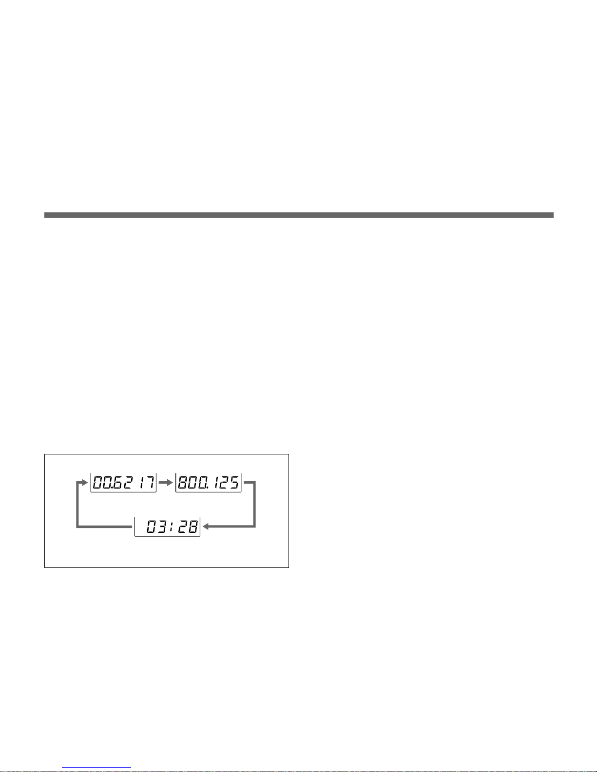
Resetting the Accumulated Time Indication ............... 11
Connections ...................................................................... 11
Microphone System Operation ...................................... 12
Muting Functions ......................................................... 12
Error Messages ................................................................ 13
Use of the Soft Case ......................................................... 14
Specifications.................................................................... 15
Wireless Channel Lists .................................................. L-1
WRR-805A/CE62 Model .......................................... L-5
WRR-805B/CE59 Model......................................... L-15
WRR-805B/CE68 Model......................................... L-21
Table of Contents

2(GB)
WRR-805B/CE59 model
A 16-MHz frequency band is assigned to the WRR-805B/
CE59 model, permitting it to operate on any of 126 carrier
frequencies in 125-kHz steps of Sony original channel plan
or 640 carrier frequencies in 25-kHz steps in the range of
TV channels 59 and 60.
For the selectable channels, see
“Wireless Channel Lists” on
page L-1 and L-4 and L-15 to L-20.
WRR-805B/CE68 model
A 16-MHz frequency band is assigned to the WRR-805B/
CE68 model, permitting it to operate on any of 127 carrier
frequencies in 125-kHz steps of Sony original channel plan
or 640 carrier frequencies in 25-kHz steps in the range of
TV channels 68 and 69.
For the selectable channels, see
“Wireless Channel Lists” on
page L-1 and L-4 and L-21 to L-26.
Features
Phase Locked Loop (PLL) synthesized system
The WRR-805A/805B has a refined phase locked loop
(PLL) synthesizer circuit.
Preprogrammed wireless channel plans for simultaneous
multi channel operation
The WRR-805A/805B has many preprogrammed channel
groups, meaning combination of wireless channels to permit
simultaneous operation of multiple channels without
intermodulation.
Any available group and channel can be selected with a
simple button operation.
Compact and lightweight
Mounting technology and the versatile soft case enable this
compact and lightweight tuner, which lets you move
anywhere for Electronic News Gathering (ENG) and
Electronic Field Production (EFP).
Remote battery alarm from transmitter
This tuner has capability of receiving “Battery status
information” from the transmitter WRT-805B/822B to make
advance warning of battery depletion.
The information is sent in approx. one hour advance to
battery exhaust so that you can safely replace the batteries of
the transmitter.
Operation powered by easily available batteries
The built-in high efficiency DC-DC converter allows stable
operation, for about 5 hours continuously, with two LR6
(size AA) alkaline batteries.

3(GB)
LCD for coordinated operation control
The built-in CPU controls operation of the unit, including
the PLL circuit function. The LCD shows the current
channel number/frequency, the residual battery power, AF
output level and RF input level.
An accumulated operation time indication is also provided for
simple control of the time of battery use (in one-minute
increments).
Saved channel setting
The unit stores the channel setting when it is turned off. The
saved settings are retained even if the batteries are removed.
Therefore, when using the unit next time, you need not
make the same settings again.
Wide dynamic range
The compander (compressor/expander) system enables
stable reception over a wide dynamic range.
Output monitoring
The audio output can be monitored through headphones
(either of stereo or monaural). The monitoring level is
adjustable.
Muting switch for noise elimination
Precautions
•The unit is designed for use in ambient temperature range
of 0°C to 50°C (32°F to 122°F).
•Do not place the unit on or near heat sources, such as
lighting equipment, power amplifiers, or in a place subject
to direct sunlight or excessive moisture. In such places,
the external finish or internal parts of the unit may be
damaged.
•If the unit is used in a very humid or dusty place or in a
place subject to an active or corrasive gas, clean its
surface as well as the connectors with a dry, soft cloth
soon after use.
Lengthy use of the unit in such places or not cleaning it
after its use in such places may shorten its life.
•When cleaning the unit, never use organic solvents such
as thinners or benzine, which will damage the finish of the
unit.
•The unit has been factory adjusted precisely. Do not
tamper with its internal parts or attempt to repair it.

4(GB)
ON
OFF
MUTING
RFAF
RFTXBATT
GPCH
BATT
MODE
POWER
SET
ON
OFF
MONITOR
Wire antenna
q; +/– buttons
AB
CD
7RF indicator
8TX BATT indicator
9MUTING switch
qa MONITOR control
2OUTPUT (BAL)
connector
1MONITOR
connector
3Display section
4SET button
5MODE button
6POWER switch
Battery holder
Parts Identification
1MONITOR connector
To monitor the audio output signal, connect the headphones
equipped with 3.5 mm dia. stereo mini jack. You can use
either of stereo or monaural headphones. The monitoring
level can be adjusted with the MONITOR control.
2OUTPUT (BAL) connector
Supplies audio signals. You can connect this connector to
the microphone input connector of a Camcorder, mixer, or
tape recorder by using the supplied cable.
3Display section
Shows the status of the tuner and the groups and channels
assigned to the unit.
AAF (audio frequency) indication
Lights when the output audio signal is over the reference
level.
Display example for
WRR-805A/CE62 model

5(GB)
BBATT (battery) indication
Displays the status of the batteries of this unit.
See “Battery indication” on page 7.
CRF (radio frequency) indications
The dot indications show the RF input level. Depending on
the RF input level, the number of dots changes as below.
Four dots on: more than 45 dBµ
Three dots on: between 35 dBµand 45 dBµ
Two dots on: between 25 dBµand 35 dBµ
One dot on: between 15 dBµand 25 dBµ
No dot: less than 15 dBµ
DGP/CH (group/channel) indication
Shows the reception channel group and respective channel
number.
Each time you press the MODE button the group/channel
indication changes to the frequency and accumulated time
indications as shown below.
Group/channel indication
Accumulated time indication
Frequency indication
In Accumulated time indication, it displays the accumulated
time of battery use (in one-minute increments).
See “Settings” on page 8.
4SET button
Press to change and set the contents of the item on the
display.
See “Settings” on page 8.
5MODE button
Press to select the item to be set on the display.
See “Settings” on page 8.
6POWER switch
Turns the power of the tuner ON or OFF.
7RF (radio frequency) indicator
Indicates the strength of the RF input signal.
On in green: more than 25 dBµ
On in red: between 15 dBµand 25 dBµ
Off: less than 15 dBµ(less than muting level)
8TX BATT (transmitter battery) indicator
Indicates the battery condition of the wireless microphone
transmitter. The indicator starts flashing about one hour
before the transmitter batteries go flat.
Display example for WRR-805A/CE62 model

6(GB)
Two LR6 (size AA)
alkaline batteries
9MUTING switch
Set to ON to eliminate the noise and signal interference
when the tuner is in signal reception standby mode.
See “Muting Functions” on page 12.
q; + (+ selection) / – (– selection/reset) buttons
In setting mode, select the receiving group, channel and
frequency using either of these buttons, or reset the time-of-
use indication to “00:00” with the – button.
See “Settings” on page 8.
qa MONITOR control
Turn to adjust the monitoring level through headphones.
Parts Identification Power Supply
The tuner can operate on two LR6 (size AA) alkaline
batteries continuously for about 5 hours at 25°C (77°F).
Installing the batteries
1Slide the battery-holder catches inward ( in the direction
of the arrows b b
b b
b B) to take out the battery holder.

7(GB)
1234
TTAB noitacidni
sthgiLsthgiLsehsalFffoseoG
yrettaB noitidnoc dooG nahtsseL egrahc-flah tsomlA detsuahxe yletelpmoC detsuahxe
2Match the polarities and insert the batteries.
3Set the battery holder in the original position.
Battery indication
When you turn the power on, the battery status of this unit
appears in the BATT indication on the display section.
Note
The indication may be incorrect if the batteries are not new
when installed. If you plan to use the tuner for a long
period, it is best to replace the batteries with new ones.
Notes on batteries
•Use new alkaline batteries.
•Do not pair different types of batteries.
•Always replace the two batteries together.
•The batteries are not rechargeable.
•Be careful to install the batteries with the correct polarity.
•When not using the tuner for a long period, remove the
batteries to avoid leakage. If the batteries do leak, clean all
leakage from the battery holder case and the unit. Leakage
left in the holder case and the unit may cause poor battery
contact. If there seems to be poor battery contact, consult
your Sony dealer.

8(GB)
2Press the MODE button until the group name and channel
number appear on the display.
3Press the SET button.
The tuner enters in group selection mode and the group
name flashes on the GP section.
4Press the + or – button to select the group.
The indication will cycle as shown on next page.
Pressing the + button cyclically changes the group
indication in the arrow →order.
Pressing the – button changes it in the reversed order.
If you hold either button pressed, the group setting will
change continuously.
When no button is pressed for more than 30 seconds, the
group selection mode or the subsequent wireless channel
selection mode is automatically released.
In group selection mode
Display example for WRR-805A/CE62 model
1
23, 5, 7
4, 6
Note
Noise may occur when the power is turned on or off. Be
sure to turn down the input level of the connected equipment
before operating the POWER switch.
1Set the POWER switch to ON.
The display shows the same status as before the tuner was
last turned off.
If the group name and channel number is shown on the
display, skip step 2and proceed with step 3.
Settings
Wireless Channel Selection
RF AF
RF TX BATT
GP CH
BATT
MODE
POWER
SET
ON
OFF
MONITOR

9(GB)
6Press the + or – button to select the channel.
Pressing the + button cyclically changes the channel
indication in the order shown in the table of the selected
group in “Wireless Channel List” on page L-5 to L-26.
Pressing the – button changes it in the reversed order.
If you keep either button pressed, the channel number
will be incremented or decremented continuously.
5Once the desired group indication appears, press the SET
button.
The group selected is set.
The tuner now enters the wireless channel selection
mode, and both of the TV channel number and two digits
number flash on the display as shown on the right
column.
On the WRR-805A/CE62 model
On the WRR-805B/CE59 model
On the WRR-805B/CE68 model
Display example for WRR-805A/CE62 model
In channel selection
mode
(Continue)
When the group 00 is selected for WRR-805A/CE62 model

10(GB)
Notes
•Do not remove the batteries during group and wireless
channel selection. If they are inadvertently removed, re-
insert them immediately and repeat the above steps from
the beginning.
•Make sure that the channel selected is the same as that
selected on the transmitter used in the same system.
•Depending on the noise or interference conditions, the
selectable channels may not necessarily all be usable. If
necessary, you can determine the usable channels by
stepping the channel selection through a number of
channels on the tuner with the microphone/transmitter set
to OFF. Those channels on which the RF indicator of the
tuner does not light are usable.
•If there is a TV broadcasting station near by, do not use
the station's channel.
•The unit may not operate correctly if it is turned on again
immediately after turning off the power while in setting
mode. Pause for a few seconds or more before turning on
the power again.
•When operating two or more UHF wireless microphone
systems using channels in different groups, ensure that the
systems are at least 100m (330 feet) apart from each other.
(The same applies also when using channels in a group if
the different UHF wireless microphone systems are
installed where they are within sight of each other.)
7Once the desired wireless channel is displayed, press the
SET button.
The display stops flashing and the selected group and
wireless channel are now stored in memory.
To select the channel by frequency indication
1Turn on the unit and press the MODE button until the
frequency indication appears on the display.
2Press the SET button.
The frequency indication starts flashing.
3Press the + or – button to select the channel frequency.
4Once the desired frequency is displayed, press the SET
button.
The display stops flashing and the selected channel
frequency is now stored in memory.
Settings
In frequency selection
mode
Display example for WRR-805A/CE62 model

11(GB)
Accumulated time
Resetting the Accumulated Time Indication
The time indication accumulates time in hours and minutes
when the WRR-805A/805B is on.
Reset the indication to “00:00” whenever you replace the
batteries so that it can display the running time of the
batteries.
1Press the MODE button until the accumulated time
appears on the display.
2Press the SET button.
3Press the – button.
The time indication resets to “00:00.”
While you see “00:00” is flashing, you can go back to
previous value by pressing the + button.
4Press the SET button.
Connections
Caution
When connecting the unit to a camcorder, be sure to turn the
unit off.
Connect the OUTPUT (BAL) connector to the microphone
input connector on DSR-250, DCR-VX2000 or other
camcorders by using the supplied cable.
To secure the output cable connection, be sure to turn and
lock the connector cover as illustrated below.
For attaching the unit to a camcorder, see “Use of the Soft
Case”on page 14.
To monitor audio output, connect the headphones to the
MONITOR connector. The monitoring level can be adjusted
by turning the MONITOR control.

12(GB)
Microphone System Operation
1Set the MUTING switch ON before turning on the tuner.
2Set the POWER switch to ON.
3Set the reception channel.
For details on setting the channels, see page 8.
4Set the MUTING switch OFF, and turn on the transmitter
or the wireless microphone.
If noise is heard
Depending on the environment where the system is
installed, outside noise or radio wave may disrupt the
transmission of certain channels.
To select a channel under this circumstance, turn off the
wireless microphone or transmitter. Then select a channel at
which the RF indicator is off. (A channel free from noise or
radio wave interference is selected.) Set the same channel on
the microphone or transmitter.
Muting Functions
When the MUTING switch is set to ON, the following
muting functions work in combination.
(1) Muting by RF input level
As sufficient S/N for the audio output may not be obtained if
no RF signal is received or the RF input level is low. The
audio output can be muted when the RF input level falls
below the muting level (15dBµ).
(2) Tone squelch
The audio output is obtained only when the unit receives an
RF signal which includes a specified tone signal. The audio
output is muted to eliminate noise which may be heard when
the transmitter is turned on/off or the unit receives an
interference RF signal.
(3) Noise squelch
The audio output is muted to eliminate noise which may be
heard when there is such excessive interference RF signal
that the tone squelch does not work.

13(GB)
When a problem occurs, one of the following error message
may appear on the display.
Messages Contents Measures
ERROR 03 The battery voltage exceeds the allowable value. Use the specified batteries.
ERROR 11 An error occurred in backup memory data. The memory data is initialized. Reset the group and
channel settings.
ERROR 21 The PLL synthesized circuit is in trouble. Contact your Sony dealer.
ERROR 51 Defect of the A/D converter. Contact your Sony dealer.
Notes
To eliminate interference or noise, please note the
following.
•Do not use two or more wireless microphones or
transmitters whose wireless channels are the same.
•The number of wireless channels actually usable in a
multi-channel system may be smaller than the normal
capacity of that system if there is interference from TV
broadcasting or other RF signals.
•When using two or more WRR-805A/805Bs, do not
directly put one unit upon the other.
Error Messages

14(GB)
1
2
Use of the Soft Case
The soft case can be used as shown below.
Output cable holder
To microphone
input of the
camcorder
Cable
holders
Inserting the unit in reverse direction
MONITOR connector
can be used without
hindrance.
Detaching the belt clip
While pressing down the shoe on the case
1, pull out the belt clip 2.
Attaching the unit to a handle
or a belt Turning the unit Attaching the unit to a camcorder
or

15(GB)
Specifications
Tuner section
Type of reception F3E
Circuit system Dual conversion superheterodyne
Receiving frequencies
WRR-805A/CE 62 model:
800.000 - 814.000 MHz
WRR-805B/CE 59 model:
774.025 - 790.000 MHz
WRR-805B/CE 68 model:
846.025 - 862.000 MHz
Local oscillators Crystal controlled PLL synthesizer
Selectivity 60 dB or more (at ±250 kHz detuned)
Spurious rejection ratio
70 dB or more
Image rejection ratio
60 dB or more
Muting level 15 dBµ ±5 dBµ
Type of antenna 1/4- wavelength wire
Frequency range 100 Hz to 15,000 Hz ±3 dB
De-emphasis 50 µsec
Signal-to-noise ratio
30 dB or more at an A-weighted RF
input level of 10 dBµ
60 dB or more at an A-weighted RF
input level of 60 dBµ
(±5 kHz deviation at 1 kHz
modulation)
Distortion 1% or less (±40 kHz deviation at
1 kHz modulation)
Tone signal frequency
32.768 kHz
Output level –58 dBm (±5 kHz deviation at 1 kHz
modulation)
Output impedance 600 ohms
Output connector 3.5 mm dia., balanced
0 dBµ = 1µV
0 dm = 0.775 Vrms (600 ohms loaded)
General
Power requirements DC 3 V, two batteries LR6 (size AA)
Current consumption
Approx. 205 mA
Battery life Approx. 5 hours of continuous use
with two Sony LR6 batteries
at 25 °C (77 °F)
Operating temperature
0 °C to +50 °C (32 °F to 122 °F)
Storage temperature –20 °C to +55 °C (–4 °F to +131 °F)
Dimensions 44 ×121 ×24 mm (w/h/d)
(15/8×47/8×31/32 inches)
Mass 140 g (5 oz) including batteries
Supplied accessories
Attachment case with a belt clip (1)
Output cables (2)
Operating instructions (1)
Design and specifications are subject to change without
notice.

16(GB)

1(FR)
Français Introduction
Le WRR-805A/805B est un syntoniseur portable hautement
fiable pour système de microphone UHF sans fil Sony de la
bande de 800 MHz destiné à des applications de diffusion
ou de production cinématographique.
Ce syntoniseur convient aussi bien au journalisme
électronique (Electronic News Gathering -ENG) qu’à la
production électronique sur site (Electronic Field Production
- EFP).
Canaux sans fil sélectionnables
Le microphone/émetteur et les syntoniseurs du système de
microphone sans fil sont classés par bande de fréquence.
Une bande de fréquence de 14 MHz et une bande de
fréquence de 16 MHz sont assignées à ce modèle.
Lors de la configuration d’un système de microphone UHF
sans fil, veillez à combiner un microphone/émetteur et un
syntoniseur ayant le même numéro de canal de télévision.
Modèle WRR-805A/CE62
Une bande de fréquence de 14 MHz est assignée au modèle
WRR-805A/CE62, ce qui lui permet de fonctionner sur l'une
des 111 fréquences porteuses du plan des canaux original
Sony par incréments de 125 kHz ou sur l'une des 561
fréquences porteuses des groupes d'utilisateurs allemands
par incréments de 25 kHz dans la bande des canaux de
télévision 62 et 63.
Table des matières
Introduction ....................................................................... 1
Canaux sans fil sélectionnables ..................................... 1
Caractéristiques .............................................................. 2
Précautions ......................................................................... 3
Identification des composants .......................................... 4
Alimentation....................................................................... 6
Réglages .............................................................................. 8
Sélection d’un canal sans fil .......................................... 8
Remise à zéro de l’indication de temps accumulé ....... 11
Raccordement .................................................................. 11
Fonctionnement du système de microphone ................. 12
Fonctions de coupure ................................................... 12
Messages d’erreur ........................................................... 13
Utilisation de l’étui souple............................................... 14
Spécifications.................................................................... 15
Listes des canaux sans fil .............................................. L-1
Modèle WRR-805A/CE62 ......................................... L-5
Modèle WRR-805B/CE59 ....................................... L-15
Modèle WRR-805B/CE68 ....................................... L-21
N-
Français
FR

2(FR)
Introduction
Pour connaître les canaux sélectionnables, voir “Listes des
canaux sans fil” aux pages L-1, L-3, et aux pages L-5 à L-14.
Modèle WRR-805B/CE59
Une bande de fréquence de 16 MHz est assignée au modèle
WRR-805B/CE59, ce qui lui permet de fonctionner sur l'une
des 126 fréquences porteuses du plan des canaux original
Sony par incréments de 125 kHz ou sur l'une des 640
fréquences porteuses par incréments de 25 kHz dans la
bande des canaux de télévision 59 et 60.
Pour connaître les canaux sélectionnables, voir “Listes des
canaux sans fil” aux pages L-1, L-4, et aux pages L-15 à L-20.
Modèle WRR-805B/CE68
Une bande de fréquence de 16 MHz est assignée au modèle
WRR-805B/CE68, ce qui lui permet de fonctionner sur l'une
des 127 fréquences porteuses du plan des canaux original
Sony par incréments de 125 kHz ou sur l'une des 640
fréquences porteuses par incréments de 25 kHz dans la
bande des canaux de télévision 68 et 69.
Pour connaître les canaux sélectionnables, voir “Listes des
canaux sans fil” aux pages L-1, L-4, et aux pages L-21 à L-26.
Caractéristiques
Système synthétisé en boucle à verrouillage de phase
(PLL)
Le WRR-805A/805B comporte un circuit synthétisé en
boucle à verrouillage de phase (PLL) élaboré.
Plans de canaux sans fil préprogrammé pour
fonctionnement simultané de plusieurs canaux
Le WRR-805A/805B comporte plusieurs groupes de canaux
préprogrammés autorisant des combinaisons de canaux sans
fil qui permettent le fonctionnement simultané de plusieurs
canaux sans intermodulation.
Un groupe et un canal disponibles peuvent être sélectionnés
en appuyant simplement sur une touche.
Compact et léger
La technologie de montage employée, le boîtier en
magnésium et l’étui souple polyvalent contribuent à la
compacité et à la légèreté de ce syntoniseur, qui vous permet
de vous déplacer n’importe où pour vos activités de
journalisme électronique ou de production électronique sur
site.
Alarme de piles à distance depuis l’émetteur
Ce syntoniseur est capable de recevoir des “ informations
d’état des piles” depuis l’émetteur WRT-805B/822B pour
lancer un avertissement d’épuisement des piles.
Les informations sont envoyées environ une heure avant
l’épuisement de la pile de façon à ce que vous puissiez
remplacer les piles de l’émetteur.
Alimentation sur piles ordinaires
Le convertisseur CC-CC intégré à haute efficacité assure un
fonctionnement stable d’une durée d’environ 5 heures en
continu avec deux piles alcalines LR6 (AA).
Other manuals for WRR-805A
2
This manual suits for next models
1
Table of contents
Other Sony Tuner manuals

Sony
Sony SVR-2000 User manual

Sony
Sony WRR-801A User manual

Sony
Sony WRR-850A User manual

Sony
Sony ST-S444ES User manual

Sony
Sony ST-S3000ES User manual

Sony
Sony MB-8N User manual

Sony
Sony Ipela NSR-S10 User manual

Sony
Sony R-D-S EON ST-SE700 User manual

Sony
Sony WRR-862A User manual

Sony
Sony WRR-805A User manual