Sony URX-S03D User manual

UHF Synthesized
Diversity Tuner
Operating Instructions
URX-S03D
4-590-341-11 (1)
© 2016 Sony Corporation

2
Table of Contents
Features .......................................................3
Parts Identification......................................4
Preparation ..................................................5
Attaching to a Camcorder............................. 5
Using Wireless Adapters .............................. 5
Settings ........................................................5
Setting the Receive Channel......................... 5
Searching for Available Channels within a
Group (Clear Channel Scan) ............... 6
Searching for Active Channels within a Group
(Active Channel Scan) ........................ 6
Setting the Compander Mode ....................... 6
Using the Squelch Function.......................... 7
Using the Infrared Communication
Function............................................... 7
Menu Displays and Detailed Settings........9
Menu Structure and Hierarchy...................... 9
Basic Menu Operations................................. 9
UTILITY Menu ............................................ 9
RX (tuner) 1/2 Menu .................................. 10
Error Messages .........................................11
Troubleshooting ........................................12
Important Notes on Use............................13
Usage and Storage ...................................... 13
Cleaning...................................................... 13
Specifications............................................13

3
Features
The URX-S03D UHF Synthesized Diversity Tuner is a
two-channel slot-in wireless tuner that can be used in
conjunction with Sony professional camcorders and
optional wireless adapters.
Two-channel camcorder-slot-in receiver
The unit is a camcorder slot-in receiver that supports
systems that include two transmitters operating
simultaneously. If your camcorder does not support slot-
in mounting, you can attach the unit to an optional DWA-
01D or DWA-F01D wireless adapter.
XDCAM compatibility
The two channels of digital signals processed by the
unit’s DSP can be sent directly to the camcorder via the
15-pin D-sub connector. The RF/AF levels of each
wireless microphone can also be viewed via the
camcorder’s viewfinder.
HDCAM compatibility
The units’ single channel of analog output signals can be
sent directly to the camcorder via the 15-pin D-sub
connector. Two different audio signals sent from two
transmitters can also be mixed for output as a single-
channel audio signal.
The RF/AF levels of each wireless microphone can also
be viewed via the camcorder’s viewfinder. When both
channels are enabled, channel 1 is displayed. When only
one channel is enabled, that channel is displayed.
True diversity system
The unit is equipped with two lines of reception for each
channel that can receive signals from the transmitter
simultaneously. The true diversity system determines the
stronger of the two antennas signals and selects it
automatically, achieving highly stable reception with
minimal interruption and noise across a wide area.
Compatibility with Sony analog wireless
microphones
The built-in DSP enables digital companding for high-
quality audio transmissions. Switching to compander
mode allows operation in conjunction with Sony analog
wireless microphone system (UWP series and WRT
series) transmitters.
High-visibility display
The area of the display screen is twice that of previous
models, providing enhanced visibility. The built-in
backlight also allows easy settings changing in even the
darkest of shooting locations.
Channel scanning
Clear channel scanning for detecting unoccupied
channels and active channel scanning for detecting used
channels allow you to quickly assess the situation at a
location and configure the appropriate channel.
Built-in infrared communication function
When operating in conjunction with UWP-D series
transmitters, the frequency and compander mode settings
configured on the unit can be sent using the infrared
communication function, allowing you to complete
channel configurations quickly.
Sturdy construction for use outdoors
Designed to withstand rough outdoor conditions with its
solid dust-proof body, the unit meets JIS II drip-resistance
standards when mounted on a camcorder with its
antennas attached.
Switchable squelch function
A squelch function that can be turned on or off depending
on the situation is available.

4
Parts Identification
aAntenna connector (BNC type)
Connect the supplied antenna here.
bMounting screw
Use to attach the receiver to a camcorder or wireless
adapter.
cAccessory connector (15-pin D-sub)
Use to connect the receiver to a camcorder or wireless
adapter. Power, audio, and control signals are sent
through this connector.
dPOWER indicator
Lights up green when the power is on.
The POWER1 and POWER2 indicators indicate the
power status of tuner 1 and tuner 2, respectively.
eRF (radio frequency) indicators
Indicate the RF input level of tuner 1 and tuner 2.
On in green: 25 dBµ or more
On in red: 15 dBµ to 25 dBµ
Off: Less than 15 dBµ
0 dBµ = 1 µVEMF
fPOWER switches
Turn tuner 1 and tuner 2 on or off individually.
gMENU button
Selects the displayed menu.
hSET button
Changes the item to be set or enters the selected function
or parameter value.
i+ or – button
Use to select a function or value.
jInfrared transmission port
Transmits the frequency and compander mode settings
configured on the unit to the transmitter.
kDisplay section
AAudio input level meter
Indicates the input signal level.
BPeak indicator
Warns of excessive input by lighting up when the signal
is 3 dB below the level at which distortion begins.
CGroup display
Displays the name of the receive group that is configured.
DChannel display
Displays the name of the receive channel that is
configured.
ERF level meter
Indicates the RF input level. The number of segments that
light up depends on the input level.
5 segments lit: 50 dBµ or higher
4 segments lit: 40 to 49 dBµ
3 segments lit: 30 to 39 dBµ
2 segments lit: 20 to 29 dBµ
1 segment lit: 10 to 19 dBµ
All segments off: 10 dBµ or less
Meter display

5
Preparation
Attaching to a Camcorder
This receiver can be inserted into a slot provided on
compatible Sony camcorders.
1
Remove the cover from the slot for the wireless
receiver on the camcorder, and insert the receiver into
the slot.
To avoid inserting the receiver in the wrong direction,
confirm the location of the mounting screws before
inserting the wireless receiver.
2
After inserting the receiver completely into slot,
securely fasten the four mounting screws.
Using Wireless Adapters
Attaching the unit to an optional DWA-01D or DWA-
F01D wireless adapter allows you to use the unit as a
portable wireless receiver.
For details on attaching the unit, refer to the operating
instructions supplied with the DWA-01D or DWA-F01D.
Settings
Setting the Receive Channel
For details about the channel groups and channels that can
be selected, refer to the “Frequency List” on the
CD-ROM.
To prevent interference and noise, beware of the
following.
• Do not use multiple transmitters that have been set to
the same channel at the same time.
• When using two or more channels at the same time,
always configure different channels within the same
group.
• Keep all transmitters and receivers at least 3 m away
from each other.
1
Set the POWER 1 or POWER 2 switch to ON.
2
Press the MENU button to display the RX1 or RX2
menu, and press the + or – button to display the GP/
CH screen.
3
Press and hold the SET button for 1 second or longer.
The channel group display starts flashing.
4
Use the + or – button to select the desired group
name, then press the SET button.
The channel group is set, and the channel number
display starts flashing.
5
Use the + or – button to select the desired channel
number, then press the SET button.
The displays stops flashing and the desired channel is
set.
Receiver
Note

6
• If there is no user input within 10 seconds after the
channel group display or channel number display starts
flashing, the displayed setting that is flashing is saved.
The same applies when setting other parameters.
• The frequency indicator changes in response to the
channel number.
• The unit continues to receive, even when setting the
receive channel.
• Make sure that the same channel is set on transmitters
and receivers within the same system.
Searching for Available Channels
within a Group (Clear Channel
Scan)
You can search for available channels within the
specified channel group.
Before performing this procedure, select the channel
group.
For details, see “Setting the Receive Channel” (page 5).
1
Press the MENU button to display the RX1 or RX2
menu, and press the + or – button to display the CLR
SCAN screen.
2
Press and hold the SET button for 1 second or longer.
Press and hold until the channel group and “+”
display starts flashing.
3
Press the + button.
The unit starts to scan through the selected channel
group. When available channels are found, the first
channel number among the available channels starts
flashing on the display.
To display the next available channel number
Press the + button.
To cancel searching
Press the – button. The display returns to the CLR
SCAN screen.
4
Press the SET button when the desired channel
number starts flashing.
The search for available channels finishes and the
displayed channel is set.
Searching for Active Channels
within a Group (Active Channel
Scan)
You can search for channels in use within the specified
channel group. This is useful when using more than one
receiver in combination with a single transmitter.
Before performing this procedure, select the channel
group.
For details, see “Setting the Receive Channel” (page 5).
1
Press the MENU button to display the RX1 or RX2
menu, and press the + or – button to display the ACT
SCAN screen.
2
Press and hold the SET button for 1 second or longer.
Press and hold until the channel group and “+”
display starts flashing.
3
Press the + button.
The unit starts to scan for active channels in the
selected channel group. When active channels are
found, the first channel number among the active
channels starts flashing on the display.
To display the next active channel number
Press the + button.
To cancel searching
Press the – button. The display returns to the ACT
SCAN screen.
4
Press the SET button when the desired channel
number starts flashing.
The search for active channels finishes and the
displayed channel is set.
Setting the Compander Mode
Depending on the transmitter being used in conjunction
with the unit, changing the compander mode may be
necessary.
You can configure different compader modes for tuner 1
and tuner 2.
Notes

7
• When operating in conjunction with UWP-D series
transmitters, set the transmitters to the same compander
mode.
• No audio will be output if the tone signal frequency is
different due to inconsistencies in compander mode
settings configured on the devices being used together.
• When the squelch function (page 7) is set to OFF, audio
will be output even when compander mode settings are
not consistent. However, phenomena, such as changes
in output level, may occur in such cases.
1
Press the MENU button to display the RX1 or RX2
menu, and press the + or – button to display the
COMPANDER screen.
2
Press and hold the SET button for 1 second or longer.
The selected item starts flashing.
3
Use the + or – button to select the compander mode,
then press the SET button.
The selected compander mode is configured.
UWP-D: Select this when operating in conjunction
with Sony UWP-D series transmitters.
UWP: Select this when operating in conjunction with
Sony UWP series transmitters.
WL800: Select this when operating in conjunction
with Sony WRT series transmitters.
Transmitter and compander mode
combinations
Configure the appropriate compander mode based on the
transmitters being used.
Audio will not be output if the combination of
transmitters and compander mode settings are not correct.
Using the Squelch Function
Using the squelch function allows you to suppress
unwanted signals and noise while waiting for
transmissions. Set the function to ON under normal
circumstances. Set the function to OFF when you are
searching for radio interference or external noise, for
example.
The following squelch functions are available on the unit.
However, the functions can only be enabled or disabled
together and not individually.
• RF (radio frequency) squelch
Audio output is muted if the RF input level drops below
the RF squelch level. The RF squelch level is fixed.
• Tone squelch
Audio output is muted unless radio waves that include
specific tone signals are received.
• Noise squelch
Audio output is muted if the noise level rises above a
specific level.
Be sure to lower the volume on all connected devices
before performing squelch function operations. If you
disable the squelch function while waiting for
transmissions or receiving low-level RF inputs, for
example, the connected devices and speakers may be
damaged due to noise.
1
Press the MENU button to display the RX1 or RX2
menu, and press the + or – button to display the
SQUELCH screen.
2
Press and hold the SET button for 1 second or longer.
The selected item starts flashing.
3
Use the + or – button to select whether to turn the
squelch function ON/OFF, then press the SET button.
Using the Infrared Communication
Function
When operating in conjunction with UWP-D series
transmitters, the frequency and compander mode settings
configured on the unit can be sent and applied to the
transmitter using the infrared communication function.
Notes
Note
Transmitter Compander mode on
unit
UWP-D UWP WL800
UWP-D series
(UTX-B03,
UTX-M03,
UTX-P03,
UTX-B03HR)
Compander
mode: UWP-D
Ye s N o N o
Compander
mode: UWP
No Yes No
Compander
mode: WL800
No No Yes
UWP series (UTX-B2, UTX-H2,
UTX-P1)
No Yes No
WRT series (WRT-822, etc.) No No Yes
Note
Transmitter Compander mode on
unit
UWP-D UWP WL800

8
This function cannot be used when operating in
conjunction with UWP or WRT series transmitters.
Searching for available channels and
configuring the channel settings via
infrared communication (AUTO SET)
1
Press the MENU button to display the RX1 or RX2
menu, and press the + or – button to display the
AUTO SET screen.
2
Press and hold the SET button for 1 second or longer.
“YES” flashes on the display.
3
Press the SET button.
Clear Channel Scan starts searching for an available
channel.
When Clear Channel Scan finishes, the channel with
the least noise and interference will be set.
When the channel is set, infrared transmission starts
automatically.
Some noise may occur when power is turned on.
Accordingly, turn down the audio input level of
devices connected to the unit when turning the power
on.
4
Press and hold the SET button on the transmitter and
press the POWER/MUTING button to turn the power
on.
5
Place the infrared transmitter port on the unit near the
infrared detector on the transmitter.
Information about the channel set on the unit is sent
to the transmitter, and a prompt appears on the
transmitter display asking if you want to change to
that frequency.
6
Use the + or – button to select “YES,” then press the
SET button on the transmitter.
This sets the transmit channel and compander mode.
• The infrared transmission from the unit in step 3
continues for about 10 seconds. Perform steps 4
and 5within those 10 seconds. If 10 seconds have
elapsed, you can reestablish the infrared link using
the SYNC screen on the unit.
• Place the unit and transmitter within about 20 cm (8
in.) of each other.
• If 5 seconds elapse without any user input after the
prompt appears on the transmitter display, the
transmitter returns to its previous state without
changing the frequency.
• Communications using the infrared link may be
adversely affected, depending on the surrounding
environment. If this occurs, use the SYNC screen
on the unit to reestablish the link.
Configuring the group/channel manually
and configuring the channel settings via
infrared communication (SYNC)
1
Configure the group/channel settings (page 5).
2
Press the MENU button to display the RX1 or RX2
menu, and press the + or – button to display the
SYNC screen.
3
Press and hold the SET button for 1 second or longer.
A confirmation screen appears.
4
Use the + or – button to select “YES,” then press the
SET button.
5
Press and hold the SET button on the transmitter and press
the POWER/MUTING button to turn the power on.
6
Place the infrared transmitter port on the unit near the
infrared detector on the transmitter.
Information about the channel set on the unit is sent
to the transmitter, and a prompt appears on the
transmitter display asking if you want to change to
that frequency.
7
Use the + or – button to select “YES,” then press the
SET button on the transmitter.
This sets the transmit channel and compander mode.
Note
Note
Notes

9
Menu Displays and
Detailed Settings
Menu Structure and Hierarchy
Menu structure
The following two menus are available for the unit.
UTILITY menu
A menu that includes meter indications and functions that
are available when the unit is used in conjunction with a
wireless adapter.
RX1/RX2 (tuner 1/2) menu
A menu that includes receive frequency setting and tuner
setting functions.
Menu hierarchy
Basic Menu Operations
1
Press the MENU button repeatedly to select the
menu.
Each time you press the MENU SELECT button, the
menu changes in the following order:
UTILITY, RX1, RX2, UTILITY
2
Press the + or – button repeatedly until the function to
be set appears.
3
Hold down the SET button until the item to be set
flashes.
4
Press the + or – button to change the setting.
5
Press the SET button to apply the setting.
When the tuner is turned off, the menus corresponding to
that tuner are not displayed.
UTILITY Menu
The UTILITY menu includes items related to the basic
receiver settings, including meter displays.
These functions and parameters are explained here.
Underlined items are the factory setting.
The functions indicated by “ADAPTER” in the upper-
right corner are related to the AES/EBU output when the
receiver is used in conjunction with an optional wireless
adapter. The function does not operate even when used
with a compatible Sony slot-in type camcorder.
Selecting output 1 (ANALOG OUT1)
Select the output signal for when a camcorder with only
one channel of analog input (e.g., HDCAM) is connected.
In addition, when the unit is attached to a DWA-01D
wireless adapter and you are using the OUTPUT 2
connector of the DWA-01D for AES/EBU output, select
MENU
UTILITY Meter indication
ANALOG OUT 1
AES LEVEL
SYNC SOURCE
75ohm
TIME
CONTRAST
RESET
VERSION
RX1 GP/CH
AUTO SET
BAND
CLR SCAN
SYNC
COMPANDER
ACT SCAN
SQUELCH
RX2 GP/CH
AUTO SET
BAND
CLR SCAN
SYNC
COMPANDER
ACT SCAN
SQUELCH
To UTILITY menu
Note
Note
Function name
Menu name
Item to be set

10
the signal to be used as the OUTPUT 1 connector’s sub
output.
• OUTPUT 2 settings cannot be configured.
• Adjust the volume for each channel using the attenuator
function on the transmitter.
RX1: Outputs the audio signal received on tuner 1.
RX2: Outputs the audio signal received on tuner 2.
RX1+2: Mixes and outputs the audio signals received on
tuners 1 and 2.
Selecting the AES/EBU output reference
level (AES LEVEL)
Select the reference level for the AES/EBU output of an
optional wireless adapter.
The function does not operate for analog output.
– 36dB LINEAR:The audio signal from the transmitter
is output with a headroom of 36 dB.
– 20dB LIMIT: The reference level is changed to –20
dBFS in conformity with the normal AES/EBU interface
and the audio signal from the transmitter is compressed.
– 20dB ST LIM: The reference level is changed to –20
dBFS (as in the –20dB LIMIT mode above) and audio
signal compression is linked for tuner 1 and tuner 2.
Select this setting when sending stereo audio signals
using 2 transmitters.
Selecting the sync signal (SYNC SOURCE)
Select the sync signal source for the receiver when it is
attached through the optional wireless adapter. The
receiver supports an external sync signal (word clock) of
32 kHz –6% to 96 kHz +6%.
For details on locking the sync signal, refer to the
operating instructions supplied with the wireless adapter.
INTERNAL: The internal sync signal (48 kHz) is used.
AUTO: The external sync signal is used on a priority
basis. When there is no external sync signal input, the
internal sync signal is used automatically. The currently
selected sync signal is displayed “INTERNAL” or
“EXTERNAL.”
EXTERNAL: Synchronization with an external word
clock signal. The current synchronization status is
displayed “UNLOCK” or “LOCK.”
Terminating the sync signal (75ohm)
This function provides termination for the WORD SYNC
connecter on the wireless adapter.
ON: 75-ohm termination is added.
OFF: 75-ohm termination is not added.
When the receiver is turned off, the termination is
released.
Displaying the accumulated running time
(TIME)
Display the accumulated running time of the unit as a
guide to total usage time.
The factory default setting is 00:00. Up to 99:99 can be
displayed.
To reset the time display
1
Press and hold the SET button until the time display
starts flashing.
2
Press the – button to display “00:00 CLR” and press
the SET button.
Pressing the + button when “00:00 CLR” is displayed
causes the time display to start flashing. You can
press the SET button in this state to cancel the reset of
the accumulated running time.
Setting the display contrast (CONTRAST)
Adjust the contrast of text and icons on the display in the
range 1 to 10.
The configurable values are given below.
(Light) 1 2 3 4 5 6 7 8 9 10 (Dark)
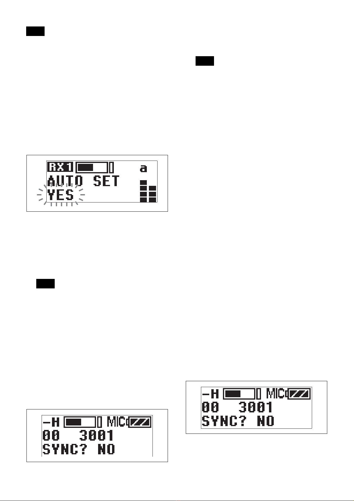
Restoring factory default settings
(RESET)
Restore all parameters to their factory default settings.
Press and hold the SET button. A prompt appears asking
you whether to restore factory default settings. Press the
+ or – button to select YES, then press the SET button.
The unit parameters are restored to their factory default
settings.
Displaying the software version
(VERSION)
Display the software version of the unit.
RX (tuner) 1/2 Menu
For details on menu operation, see “Basic Menu
Operations” (page 9).
Use this menu to set the digital wireless receiver functions
(the main functions of this receiver).
Selecting group/channel (GP/CH)
The factory default setting varies depending on the
model.
For details, see “Setting the Receive Channel” (page 5).
Notes
Note
Note

11
Setting an available channel automatically
(AUTO SET)
Automatically search for and set an available channel,
and start infrared transmission to the transmitter.
For details, see “Searching for available channels and
configuring the channel settings via infrared
communication (AUTO SET)” (page 8).
Selecting the frequency band (BAND)
Select the receive frequency band.
This menu is not available on Japanese and Korean
models. On these models, the frequency band cannot be
selected.
For details about the groups and channels in each frequency
band, refer to the “Frequency List” on the CD-ROM.
Searching for and selecting available
channels (CLR SCAN)
Search for available channels.
For details, see “Searching for Available Channels
within a Group (Clear Channel Scan)” (page 6).
Using infrared transmission (SYNC)
Transfer the frequency and compander mode set on the
unit to a transmitter using an infrared transmitter.
For details, see “Configuring the group/channel
manually and configuring the channel settings via
infrared communication (SYNC)” (page 8).
Setting the compander mode
(COMPANDER)
Set the operating mode of the compander.
For details, see “Setting the Compander Mode” (page 6).
Setting the frequency to an active channel
(ACT SCAN)
Search for channels already in use. This is useful when
using more than one receiver in combination with a single
transmitter.
For details, see “Searching for Active Channels within a
Group (Active Channel Scan)” (page 6).
Setting the squelch function (SQUELCH)
Enable the squelch function to suppress unwanted signals
and noise while waiting for transmissions.
For details, see “Using the Squelch Function” (page 7).
Error Messages
When a problem occurs, one of the following error
messages may appear on the display.
Note
Message Meaning Solution
EEP ERROR An error has
occurred in the
backup memory
data.
Contact your Sony
service representative.
PLL ERROR An error
occurred in the
PLL synthesizer
circuit.
Restart the unit. If the
message persists,
contact your Sony
service representative.
NO TONE Audio signal
output has been
muted, because
a tone signal
different from
the compander
mode
configured on
the unit was
received.
Configure the
appropriate compander
mode based on the
transmitters you are
using “Setting the
Compander Mode”
(page 6).
When operating in
conjunction with UWP-D
series transmitters
(UTX-B03, UTX-M03,
etc.), set the unit and the
transmitters to the same
compander mode.

12
Troubleshooting
If you have any problem, use the following checklist before asking for repairs. If the problem persists, contact your Sony
service representative.
Symptom Cause Solution
The unit does not turn
on.
The unit is not correctly inserted into the slot of the
camcorder or the wireless adapter.
Insert the unit until it is firmly and completely in,
and then secure it with the mounting screws.
There is no sound. The channel setting on the transmitter is different
from that on the receiver.
Use the same channel setting on both the
transmitter and receiver.
The compander mode setting on the transmitter is
different from that on the receiver.
Use the same compander mode setting on both
the transmitter and receiver.
When the receiver is attached to a wireless
adapter, the setting of the sync signal is not
appropriate.
Using the sync signal selection (SYNC SOURCE)
function, set the sync signal to INTERNAL.
When an external sync signal is used, confirm the
connection of the sync signal, and set to AUTO or
EXTERNAL.
The sound is
distorted.
The channel setting on the transmitter is different
from that on the receiver.
Use the same channel setting on both the
transmitter and receiver.
The compander mode setting on the transmitter is
different from that on the receiver.
Use the same compander mode setting on both
the transmitter and receiver.
There is sound
interruption or noise.
The channel setting on the transmitter is different
from that on the receiver.
Use the same channel setting on both the
transmitter and receiver.
Two or more transmitters are set to the same
channel.
Two or more transmitters cannot be used on the
same channel. Refer to the frequency list stored
on the supplied CD-ROM, and reconfigure the
channel on each transmitter.
The transmitters are not set to the channels within
the same channel group.
The channel plan is set so that no signal
interference occurs when two or more transmitters
are used simultaneously. Set each transmitter to a
different channel within the same channel group.
Adjacent channels are being used. Use the channels separated by at least two
channels (250 kHz).
Jamming radio waves are being received. Set the channel on the receiver to a channel for
which the RF indicator does not light, or use the
Clear Channel Scan function to switch to a
channel without interference. Then, set the
transmitter to the same channel as the receiver.
If using two or more transmitters, change to a
channel group that is not affected.
The squelch function is set to OFF. Set the squelch function to ON (page 7).
The RF indicator on
the receiver lights up
even when the
transmitter is off.
Jamming radio waves are being received. Set the channel on the receiver to a channel for
which the RF indicator does not light, or use the
Clear Channel Scan function to switch to a
channel without interference. Then, set the
transmitter to the same channel as the receiver.
If using two or more transmitters, change to a
channel group that is not affected.
The transmitter
channel cannot be set
with infrared
transmission.
The infrared receptor on the transmitter is too far
from the infrared transmission port on the receiver.
Reduce the distance between the infrared receptor
on the transmitter and the infrared transmission
port on the receiver to within about 20 cm (8 in.).
Interference from infrared communications
between other devices or from direct sunlight is
present.
The transmitting distance is reduced when
interference from strong sunlight, for example, is
present. Place the transmitter and receiver as
close to each other as possible.

13
Important Notes on Use
Usage and Storage
• Operating the UWP-D series devices near electrical
equipment (motors, transformers, or dimmers) may
cause interference due to electromagnetic induction.
Keep the devices as far from such equipment as
possible.
• The presence of lighting equipment may produce
electrical interference over a wide frequency range. In
this case, interference may fluctuate with the position of
the receiver antenna and position of the transmitter.
Position the devices so that interference is minimized.
• To avoid degradation of the signal to noise ratio, do not
use UWP-D devices in noisy places or in locations
subject to vibration, such as the following:
– Near electrical equipment, such as motors,
transformers, or dimmers
– Near air conditioning equipment or places subject to
direct air flow from an air conditioner
– Near PA (public address) loudspeakers
– Near equipment that might knock against the receiver
Keep devices as far from such equipment as possible or
use buffering material.
Cleaning
Clean the surface and the connectors of devices with a
dry, soft cloth. Never use thinners, benzene, alcohol, or
any other chemicals, since these may mar the finish.
Specifications
Antenna connector
BNC-R, 50 Ω(2)
RF squelch level
15 dBµ / OFF (0 dBµ = 1 µV)
Audio output level
–40 dBu (0 dBu = 0.775 Vrms with
modulating frequency of 1 kHz and
frequency deviation of ±5.0 kHz)
Accessory connector
D-sub connector (15-pin) (1)
Reception method
True diversity method
Local oscillator
Crystal-controlled PLL synthesizer
Receive frequencies
Models available in USA:
470 MHz to 542 MHz (UC14 model),
566 MHz to 608 MHz and
614 MHz to 638 MHz (UC30 model),
638 MHz to 698 MHz (UC42 model)
Models available in Europe:
470 MHz to 542 MHz (CE21 model),
566 MHz to 630 MHz (CE33 model),
638 MHz to 694 MHz (CE42 model),
Model available in China:
710 MHz to 782 MHz (CN38 model)
Model available in Korea:
925 MHz to 937.5 MHz (KR Model)
Model available in Thailand
794 MHz to 806 MHz (E model)
Signal-to-noise-ratio
60 dB or more (A-weighted)
Voice delay 0.375 ms
Deemphasis 50 μs
Reference frequency deviation
±5 kHz
Frequency response
40 Hz to 18 kHz
Distortion 0.9% or less (with modulating frequency
of 1 kHz and frequency deviation of
±5.0 kHz)
Tone signal In UWP-D compander mode:
32.382 kHz
In UWP compander mode: 32 kHz
In WL800 compander mode:
32.768 kHz
Indicators POWER 1/2, RF 1/2
Operating temperature
0 °C to 50 °C (32 °F to 122 °F)
Storage temperature
–20 °C to +55 °C (–4 °F to +131 °F)
Supply voltage 7.0 V DC (supplied from camcorder or
wireless adapter)
Current consumption
200 mA or less (during 7 V DC)
To prevent electromagnetic interference
Some channels may be unable to be used due to noise
generated due to the effects of external noise and/or
radio interference. In this case, it is recommended to
stop transmitting (turn the power off) or change to
another frequency (change channel).
To prevent electromagnetic interference from
portable communication devices
The use of portable telephones and other
communication devices near the devices may result in
malfunction and interference with audio signals. It is
recommended that portable communication equipment
near the devices be turned off.

14
Dimensions
88 × 116.2 × 31.2 mm
(3 1/2× 4 5/8× 1 1/4in.)
(width / height / depth)
Mass Approx. 303 g (11 oz.)
(with supplied antennas attached)
Supplied accessories
Whip antenna (2)
Before Use (1)
CD-ROM (1)
Warranty card (1)
Design and specifications are subject to change without
notice.
Notes
• Always verify that the unit is operating properly
before use. SONY WILL NOT BE LIABLE FOR
DAMAGES OF ANY KIND INCLUDING, BUT
NOT LIMITED TO, COMPENSATION OR
REIMBURSEMENT ON ACCOUNT OF THE
LOSS OF PRESENT OR PROSPECTIVE PROFITS
DUE TO FAILURE OF THIS UNIT, EITHER
DURING THE WARRANTY PERIOD OR AFTER
EXPIRATION OF THE WARRANTY, OR FOR
ANY OTHER REASON WHATSOEVER.
• SONY WILL NOT BE LIABLE FOR CLAIMS OF
ANY KIND MADE BY USERS OF THIS UNIT OR
MADE BY THIRD PARTIES.
• SONY WILL NOT BE LIABLE FOR THE
TERMINATION OR DISCONTINUATION OF
ANY SERVICES RELATED TO THIS UNIT THAT
MAY RESULT DUE TO CIRCUMSTANCES OF
ANY KIND.
88 (3 1/2) 31.2 (1 1/4)
116.2 (4 5/8)

Sony Corporation
Table of contents
Other Sony Tuner manuals

Sony
Sony ST-S3 User manual

Sony
Sony ST-S800ES User manual

Sony
Sony WRR-801A User manual

Sony
Sony WRR-850A User manual

Sony
Sony WRR-855A User manual

Sony
Sony ST-JX401 User manual

Sony
Sony WRR-802A User manual

Sony
Sony ST-JX410 - Fm/am Tuner User manual

Sony
Sony HCD-WZ5 User manual

Sony
Sony WRU-806B User manual