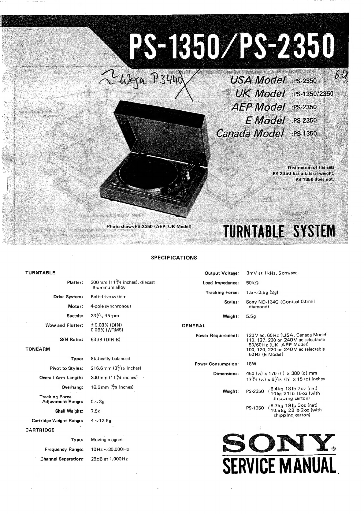
Sony PS-1350 User manual

TURNTABLE
Platter:
Drive
System:
Motor:
Speeds:
Wow
and
Flutter:
S/N
Ratio:
TONEARM
Type:
Pivot
to
Stylus:
Overall
Arm
Length:
Overhang:
Tracking
Force
Adjustment
Range:
Shell
Weight:
Cartridge
Weight Range:
CARTRIDGE
Type:
Frequency
Range:
Channel
Separation:
P,
UK
Model).
SPECIFICATIONS
Output
Voltage:
300mm
(1157/4
inches),
diecast
aluminum
alloy
Load
Impedance:
Tracking
Force:
Belt-drive
system
Stylus:
4-pole
synchronous
333,
45rpm
Weight:
+0.08%
(DIN)
0.06%
(WRMS)
GENERAL
Power
Requirement:
63dB
(DIN-8}
Statically
balanced
Power
Consumption:
216.6mm
(8716
inches)
Dimensions:
300mm
(1144
inches)
16.5mm
(7s
inches)
Weight:
O~3g
7.59
4~12.5g
Moving
magnet
10Hz
~30,000
Hz
25cB
at
1,000Hz
3mV
at
1kHz,
5cm/sec.
50KkQ
1.5~2.5g
(2g)
Sony
ND-134G
(Conical
0.5mil
diamond)
5.5g
120V
ac,
60Hz
(USA,
Canada
Model)
110,
127,
220
or
240V
ac
selectable
50/60
Hz
(UK,
AEP
Model)
100,
120,
220
or
240V
ac
selectable
50Hz
{E
Model)
18W
450
(w)
x
170
(h)
x
380
(d)
mm
1757/4
(w)
x
616
(h)
x
15
(d)
inches
8.4kg
18
1b
7oz
(net)
PS-2350
(104g
21
1b
1502
(with
shipping
carton)
ps.1350
(8-7kg
19
1b
30z
(net)
10.5kg
23
lb
20z
(with
shipping
carton)
SERVICE
MANUAL.

PS-1350/PS-2350
SECTION
1
DISASSEMBLY
AND
REPLACEMENT
1-1.
Bottom
Plate,
Wooden
Case
and
Motor
Board
Removal
[For
USA,
Canada,
E
Model]
[For
UK,
AEP
Model]
3.
motor
board
1.
Bottom
Plate:
Note:
Unpiug
the
power
cord.
Remove
ten
screws
marked
*
(@
R3.1
x
13,
wood).
1.
Bottom
Plate:
2.
Wooden
Case:
Remove
ten
screws
marked
*
(@
R3.1
x
13,
wood).
@
Remove
four
screws
marked
@
(@
PSW
4
x
25).
@
Remove
five
screws
marked
4
(@
PSW
3
x
8).
@
Remove
each
screw
(#
R3.1
x
13,
wood)
for
power
2.
Wooden
Case:
cord
strain
relief
and
phono
cord
clamp.
@
Remove
four
screws
marked
@
(@
PSW
4
x
25).
3.
Motor
Board:
Remove
two
screws
(®R
3.1
x
13,
wood)
for
phono
Remove
the
bottom
plate
and
the
wooden
case.
cord
clamp.
3.
Motor
Board:
Remove
the
bottom
plate
and
the
wooden
case.
1-5.
Cartridge
Replacement
cartridge
ae,
Unplug
four
pin-connectors
stylus
tip
z
“on
the
shell.
shell
tweezers
WHT
GRIN,
BLU
RED
~/
#
wHT
8LU
Fasten
the
screws
lightly
so
that
the
cartridge
can
be
slid
for
adjustment.
screwdriver
Remove
the
old
cartridge
stylus
tip
by
loosening
two
mounting-
screws.
49mm
(1
\6"}
mounting-screw
for
cartridge.

PS-1350/PS-2350
PS-1350/PS-2350
1-2.
Tonearm
Pipe
Replacement
1-3.
Locking
Collar
Replacement
1-4.
Tonearm
Body
Base
Removal
1.
Remove
two
screws
2.
Replace
the
locking
marked
(A)
.
collar.
auto-return
.
locking
collar
7.
Remove
a
screw.
counterweight
shaft
oe
tonearm
bady
7
s
@©®P3x
16
[CAUTION]
rubber
damper
Do
not
remove
the
tonearm
body
ass’y.
The
reassembling
of
tonearm
body
will
result
in
mechanical
screw
(A)
2.
Remove
three
hexagon-socket
Phono
circuit
board
bracket
1,
Remove
the
auto-return
lever
and
unsolder
five
lead
wires.
2.
Remove
the
arm
lifter.
3.
Remove
the
tonearm
pipe
shown
below.
tonearm
pipe
set
screw
set
screw
2.6x.3
screw
(4)
B26x6
4,
Replace
the
tonearm
pipe.
{Overhang
Adjustment]
Install
the
alignment
protractor
alignment
protractor
:
on
the
turntable
shaft.through
Bring
the
tonearm
above
the
cross
point
of
two
fine
lines,
and
carefully
lower
the
stylus
on
the
cross
point.
fine
line
,
el
lineorrect]
feorrect]
fineorrect]
Overhang
is
too
fong
Overhang
is
too
short.
(Slide
the
cartridge
backward)
(Slide
the
cartridge
forward}
tonearm
pipe
connector
tonearm
body
counterweight
shaft
1-6.
Turntable
Shaft
Removat
Pull
out
the
turntable
shaft
by
removing
a
screw
@
PSP
3
x
5.
turntable
shaft
turntable
bearing
screw
®
PSP3x
5
es
Note:
Apply
grease
on
the
turntable
shaft,
when
reinstalling
it.
1-7.
Turntable
Shaft
Bearing
Replacement
r®
nut
&
@
Place
the
turntable
shaft
bearing
by
setting
the
hole
of
screw
ta
the
front.
@
After
setting,
apply
locking
compound
here.
Apply
grease
here.
shaft
:
q
(Part
No.
7-662-001-1171}
turntable
shaft
bearing
screws,
3
x
6.
troubles.
3.
Remove
the
tonearm
body
base.
tonearm
body
base
Adaptation
to
Local
Line
Frequency
Motor
Pulleys
For60Hz
[Part
No.
X-4844.007-1]
;
For
50
Hz
{Part
No.
.
X-4844-007-2]
Procedure:
1.
Install
the
replacement
pulley,
and
set
the
speed
selector
knob
to
33
rpm
position.
.
Adjust
the
height,
of
the
motor
pulley
so
that
the
top
of
motor
pulley
is
even
with
the
top
edge
of
i
speed
selector
lever
as
shown
below.
,
speed
selector
lever
(33
rom}

SECTION
2
é
DIAGRAMS
SCHEMATIC
DIAGRAM
2-1.
USA,
Canada
Model
+
a =
+
.
.
|
WHT
|
FSS-1024A
Piano
"
ern
TCH
(AEP
Model)
~ S
2
a
VOL
TAGE
SELECTOR
2-2.
UK,
AEP
Model
BLU
£35
+
—
-—
+
VOL
TAGE
SELECTOR
!
BLU
OFF
BLU
YEL/GRN
FSS-1024A
0.2A
AC
$7
MICROSWITCH
INPUT
POWER
(UK
Model)
YEL/GRN
Note:
ze
indicates
chassis
ground.
2-3.
E
Model
-
F
+
—
=
+
VOLTAGE
SELECTOR
AC
INPUT
MICROSWITCH
3-1.
i
1.
7
“a
S2
3.
SECTION
3
ADJUSTMENTS
TONEARM
HEIGHT
ADJUSTMENT
At
Automatic
Return
Operation
.
When
the
tonearm
automatically
returns
to
its
tonearm
rest
after
playing,
check
to
see
that
the
clearance
between
the
stylus
tip
and
the
record
on
the
turntable
is
4
to
10mm
as.
shown
below.
.
If
necessary,
adjust
the
height
of
the
arm-lifter
by
loosening
its
adjustment
screw
shown
below.
arm-lif.
ee
arm-lifter
height
adjustment
screw
At
Manual
Cueing
Operation
Set
the
cueing
lever
to
“¥”
position.
Confirm
that
the
clearance
between
the
stylus
tip
and
the
record
on
the
turntable
is
4
to
10mm.
If
necessary,
adjust
the
height
of
the
tonearm
lifting
platform
by
loosening
the
tonearm
height
adjustment
screw
as
shown
below.
tonearm
height
adjustment
screw
(P
3
x
8)
motor
board
arm-lifter
3-2.
AUTOMATIC
RETURN
POSITION
ADJUSTMENT
1.
Remove
the
tonearm
from
its
rest.
2.
Loosen
thé
allen-head
screw,
and
adjust
the
tonearm
lever
so
that
the
auto-return
lever
ass’y
is
in
parallel
to
the
edge
of
chassis
as
shown
below.
3.
The
position
where
the
tonearm
starts
to
return
can
be
adjusted
by
turning
the
automatic
return
position
adjustment
screw
shown
below.
If
the
automatic
return
works
too
early,
turn
the
adjust-
ment
screw
clockwise
—-
if
too
late,
turn
the
screw
counterclockwise.
auto-return
lever
ass‘'y
microswitch
automatic
return
position
adjustment
screw
to
be
parallel
3-3.
MICROSWITCH
POSITION
ADJUSTMENT
1.
Place
the
tonearm
on
the
tonearm
rest.
2.
Set
the
microswitch
to
“OFF”
by
turning
the
adjustment
screw.
main
lever
ass’y
adjustment
screw
(PSW
3
x
16)
microswitch
3.
When
the
tonearm
is
removed
from
its
rest,
check
to
see
that
the
microswitch
is
“ON”.
4.
Repeat
the
above
step
2
and
3,
if
necessary.
5.
When
the
tonearm
returns
to
its
rest
in
automatic
return
operation,
confirm
that
the
microswitch
is
“OFF”.

peay
payiojs
=
(—)
*paiou
asimsauio
ssajun
adA1
(ss3091
ssos9)
sdijjiyq
ae
sMaios
jj
O
‘aDIAI9S
OUITINOI
410}
PasiNbas
wopyes
ase
Aayi
asnesaq
payxd01s
OU
ale
uOdI}diJOsap
ou
40/pue
saquinu
qed
ou
YUM
sal)
O
10]0N
(lapow
d3¥
‘xN)
8X
EMSd
4aqqns
‘Asif
2004
CaN
O-lzonerX
-
poom
“gx
1H
A
-
pooMm
‘ELXLEY
4agqns
“A,ssif
JOO
Pa
u
,
=
=
O-LZO-vb8P
xX
.
- C
as
eA
: .
wonog
‘ated
jepow
3
‘dav
“IN
NEY
/
;
;
$2
x9
MSd
[oo
St
=
7
poom
‘ELX
LEY
4anoo
40,2898
abeyon
‘Masag
poom
‘gixiey
!
SK
.
OO-FES-91E-b
e
;
re)
8xéa
4aq2ajas
abeIjOn
“19A0D
g
20-LE0-G08-b,
_,
apo
d3v
“xN)
a-§
4nduy
22
“soJ99UUOD
Sy
:
SS
mee
ey>
.
|
{japow
7
‘epeuen
‘YSf)
Jaljas
Ujens
“saddors.
aseo
uapoom
‘abui}}
00-1
WO
Gres,
s
BXxEd
4039888
aber0/A
8
(japou
dF
‘N)
00-G8E°60St
|
Ki
H
As
(fapouwl
J)
£2-991-92S-t
I
|
|
|
|
|
|
I
|
|
A:
:
|
>
pioa
ouoyd
‘dueya
t
|<
poom
‘ELXLEY
“|
@
payseur
qed
Buipnjout
:uapoom
‘A,
ssi7
aseD*}
(japowt
dIV
"NN
‘OGEZ-Sd)
F8L0-vb8T-X
(J0POW
NN
“OGEL-Sd)
L-BL0-vb8r-X
{japoul
epeued
“YSfi)
$-800-bv87'X
(japoul
g3¥
‘N)
“POQM
“ELX
LEY
(to)
Vz0
‘sng
OO-KLO-CESt
.
Ay
POM
“EL
XLEY
poom
‘eLxteu~
2
eee:
(apour
7
‘epeuer
‘YSN)
p10
samod
*sayjay
Wes
asea
uapoom
‘abuit
;
00°7E0-L0VE
00-1b0-628-b
ioe
40399/98
paads
‘sEA0D
{LL}
4amod
‘sausojsuest
00°800-bb8b
(pow
JV
NN)
00-GbS-
tbr
t
PS-1350/PS-2350
40}0U
“Assy
pseog
masas
ysuen
‘uonnes
"jaqe7
;
(apo
1}
Sb-veresle
(2S)
HAMOd
‘uounqysnd
“youMS
O0-LL2°91F-1
“1
Aguanbed,
aur]
oe
“jeqe7
(japouwl
JIV
NN)
ZHOG
OO-ZCL-P90-T
(iapout
gi
“epeuey
WSN)
ZHO9
00-4ZL-290-%
anseyd
‘1aysen,
00-987:
L787
~
qsuegR
‘Mas9S
LL-690-808-0
i
(jepous
J
‘epeued
‘YSN
‘dIV)
Z0-E00-bb8-b
young
yates
‘1yeys
re
a
ae
j
(apo
yn}
GxXE
sa.
|
+
—e.
;
t
juawmaredas
snAQs
aed
i
00°8S9'S
18-9
\
Lomrzy
“uoung
(japow
iN)
Yyoums
YAMOd
“ASS
_Gouy
00°900-b8-b
ZN
peay
jays
“puers
YIYMS
saMOd
“JayIesg
“
Sb
1
anup
‘Veg
|
00°68
L28-
8XEHMdLd
ae
YN)
9XE
HMLd
(japout
17)
ZL-E00-08-4
:
oa
ayqeruing
“A,ss¥y
3424S
O80LEv8rX
4ojdepe
wis
gp
‘sapjoH
B33
3mainfsmt
ure.
‘Assy
wed
PS-1350/PS-2350
O-6EL-VESE-X
8/GeRusny
“198
00°100-bb8-b
(a)
Assy
yarn
‘Eb
Main
papojdxa
att
22g
4ayed
aqeuiny
“Jey
olor
Lea
x
OO-ZELEVED
a
fe)
yong
cM
OO-9L
LEVEY
Siz
abuiy
‘Assy
qsoddng
On
96
hy
dN
4
‘
9XE
Aaysos-uobexay
‘mas9$
aS
00-L09-10LE
abuiy
‘Assy
q40ddng
ASSY
48}
ftf-UYy
OELO-bb8b-X
SECTION
4
EXPLODED
VIEWS
49n02
doz
‘Assy
abuiy
J
0-
OV.
aHASR-~
PW
do}
‘Assy
48009
L910-¢080-X
4-1.

“Bulids
uy
s}i09
JO
Jaquunu
ay
smous
(1)
5)
oO
peay
pajojs
=
(—)
*pajou
asimsayio
ssajyun
adA}
(ssa0a1
ssO1d)
sdijjiyg
ase
sass
fi
O
@O1AGS
BUIINO.
40}
Pasinbas
wopyjes
aie
Aayy
asnesaq
paxd0is
OU
ase
uUOdIIdIOSap
Ou
4O/pue
Jaquinu
wed
ou
yum
swell
O
:a}0Q)
4amod
‘pi0g.
Ubedecee
epeued)
XX-G86-EF-L
4oygeuu07/Mm
ouoyd
‘p10
(19pout
YSN
°F)
XX-1GS-ES-L
00°€90-
199-4
9XE
HMdld
“|
€
paysieu
qed
Buipryout
/soyous
‘Assy
Apjnd
(jepow
g7V¥7
‘epeued
“ysn)
2H
09
Z:L00-bb8b-X
(fpOW
dIV
‘AN)
ZH OG
L-LO0-br8b-X
4azjiys
‘saduieg
ExXgz
“dno
papinuy
‘masz
as
00°09:
10L-€
L*
qsnsyy
“Jayseyy
Le-lob-LOLé
|
9XE
HMLLd
2.
Burseaq
1yeys
ayqequim
“any
3aq
anlip
“saIpysS
7
4a2giys
49q
‘A,SSif
Jayoelg
6n7
LL-80G-ET9-L
i
Hee
4OjOU
‘A
SSYY
JayIeIG
dahay
4039a}a8
paeds
“1484S
ualysng
10°08
8-808-¢
“
dojaajas
paads
‘1aA0D
4areds
(W)
WeZOL-SS4
‘so10/W
00°800'
008-0
00-Z68-808-7
£L-000°6ES'8
mh
ESO
WN
4ojsajas
paads
‘A,
SS"
4aNa7
wu
3ay908-uobexay
‘EXE
IS
0°900-bb8t'X
°
~
Yeys
saapyf-wse
“sapuyAD
eo
4Ongys
‘HUT
ue]
4aNa]
40}f{f-WUse
“24eY4S
butids
~—
00-¢LO-bb8-b
wn
;
£59
a.
;
qeys
ajge.uiny
‘Assy
Bulseag
erp
usu
£
“Me19/M
NN
O-60L-Ev8r-X
i
00-08¢-10LE
:
Te
‘dias
peuusias
»
epee
Rael
Seip
lta,
Dap
icte
kee
ee
whe
hla
i
—_
@)
daz
fpuse
2424s
wy
9XE
HMdLd
GN
Buysds
Butids
oafes
‘apingy
»
00-Sb6-LE8P
winged
@
|
ty
e7
@
aoe
HMLLd
~~
darty-ulse
‘ASS~f
wed
oO
0-G00-vv8b-X
wn)
—
qwafas
‘Butsds
°
®
00-bLr
L284
:
dayyuse
2e4
‘Bupsds
c—
€59
‘
fe
00°8¢b-LE8
i
a.
ABLAY
UE
*18N9T
eg
jaaI1s
re
gee
LODLELLO-L
-
AIAa}
YORYD
“sapjOp{
Buuids
=
00-69¢-L78-
younjo
“10087
OO-EbO
L786
b
BIby
~
429-4.
OLXEd
}
(a/ppiu)
9M
|
(tS)
a
XX-8Z0-
915-1
|
ayeus
‘db
‘4s0j9aUUOD
Louoyd
‘pieog
yno49
parutd
4OJEINSUI
“491-4
psleog
14NI419
OuoYyd
“Jayoe1g
O00-LELLEGE
paddays
‘13eYS
Buydder-s08
“9
x
Ed
00-@9r-Lz84
9LXE
MSd
5
“a
(LZE)
Bursds
XX-GEC-OPLE
Butsds
OOzlY
Leet
ayeig
‘Assy
sana]
ujeu
‘Assy
1aAaT

PS-1350/PS-2350
4-3.
.
4.844-053-00
Shaft,
counterweight
[PS-1350}
:
vd
X-4844-017-5
(PS-2350)
aes
A
5-4824-017-1
(PS-1350)
tonearm
4-844-051-00
Counterweight
Ass’y
Damper,
rubber
]
4-844-052-00
g
Bushing
its
1-508-620-00
|
Connector,
tonearm
pipe
‘
Q
qq
[NTe@__
8
Eck
P3x
16
ppaaagee
a.»
fasher,
rubber
A
‘
is
W3
(small)
X-4844-101-1
:
Body
Ass’y,
pen
4-844-054-00
2.085-058-00
i
Collar,
locking
*
©
\
fa
cP
B26x6
x
0.)
}
4-844-045-00
;
D
(a
2
(-)F1.7x3
Pipe,
tonearm
i
Ow
a)
|
3-701-503-00
waa
ts
244-043-11
)
(Se)
So
ar
Screw,
knurled
cup;
2.6
Knob,
anti-skating
force
3
he
Es
compensator
1-509-550-00
2-085-082-00
S
&
Connector,
shell
head
Washer,
11.5mm
dia
4-844-041-00
:
|
Washer
QR
.
ie
.
4-836-836-00
Aa
iy
Spring
ae
me
i)
2)
.
w
rsa
oe.
00.
adh
4
.
crew,
shell
head
adj.
“4
4.844-039-00
xe
Cam
ri
anti-skating
force
Spring,
guide
ne
>
=
ee
oe
{
compensator
=
#3
3-140-235-XX
agree
3
Lever
Ass’y,
auto-return;
eas
ae
Spring
(26T}
including
parts
marked
@
Fatal
force
4-838-319-00
]
compensator
Screw,
cartridge
<>)
X-2089-987-6
=
ie
Lug
Ass’y
~
a
4.844-044-00
2.081-731-00
EP)
ering
3:701-438-21
Washer,
shell
head
oe
aah
4-841-040-00
Washer,
cartridge
|
Cap,
anti-
skating
force
compensator
cam
Aa
4-844-042-00
X-4844-012-0
Shelf
Head
Ass’y,
including
parts
marked
&
1~5
1-549-073-00
__-
aq
Spacer
W
3
(large)
Cartridge,
VL-32G
:
leaded
{red}
:
4-815-655-11"
tite!
(green)
P
3x
12,
self-tapping
,
a
Nut,
cartridge
x2
089-618-3
(white)
a
X-2089-618-4
(blue)
Lead
wire
Ass’y,
shell
head
Stylus,
ND-134G
ae
Supplied
with
cartridge
Note:
O
items
with
no
part
number
and/or
no
description
are
not
stocked
because
they
are
seldom
required
for
routine
service.
O
AM
screws
are
Phillips
(cross
recess)
type
unless
otherwise
noted.
(—)
=
slotted
head
©
{QOT)
shows
the
number
of
coils
in
spring.

SECTION
5
PARTS
LIST
5-1.
ELECTRICAL
PARTS
Ref.
No.
Part
No.
Description
Ref.
No.
Part
No.
Description
CPI
1-101-534-00
Encapsulated
Component
1-508-620-00
Connector,
tonearm
pipe
Fl
1-532-074-00
Fuse,
0.2
A
(UK,
AEP,
E
Model)
1-509-385-00
Voltage
Selector
(UK,
AEP
Model)
M
8-839-000-11
Motor,
FSS-1024A
1-526-165-21
Voltage
Selector
(E
Model)
$1
1-516-028-XX
Microswitch
1-509-550-00
Connector,
shell
head
$2
1-516-277-00
Switch,
pushbutton;
POWER
1-509-547-00
Connector,
ac
input;
3-p
(UK
Model).
.
(UK,
AEP
Model)
1-442-545-00
Transformer,
powe
1-534-551-XX
Cord,
power
(USA,
E
Model).
Tl
(
(UK,
AEP
Model)
1-534-985-XX
Cord,
power
(Canada
Model)
1-442-568-00
Transformer,
power
(E
Model)
1-536-324-00
Terminal
Strip,
L4L
1-207-944-11
Resistor,
wirewound,
2702;7W
1-549-073-00
Cartridge,
VL-32G
(USA,
Canada
Model)
—
"
1-551-063-00
Cord,
phono;
w/connector
5-2.
ACCESSORIES
Part
No.
Description
Part
No.
Description
1-534-819-00
Cord,
power;
3
p
(UK
Model)
3-793-814-11
Card,
caution
2-054-6
19-00
Washer,
cartridge
3-793-815-11
Card,
caution
2-056-532-00
Screw,
cartridge
3-780-806-11
Manual,
instruction
(AEP,
E
Model)
3-701-806-00
Adaptor,
manual;
45
rpm
3-780-806-21
Manual,
instruction
(USA
Model)
3-780-805-41
Manual,
instruction
(UK
Model)
3-780-805-3T
Manual,
instruction
(Canada
Model)
3-793-395-00
Gauge,
overhang
adjustment
Sony
Corporation
5HOS68-1
9-958-087-01
©
1975
Printed
in
Japan
This manual suits for next models
1
Table of contents
Other Sony Turntable manuals

Sony
Sony DVW-522 User manual

Sony
Sony PS-LX200H User manual

Sony
Sony PS-LX350H User manual

Sony
Sony PS-X50 Setup guide

Sony
Sony NW-A45 User manual

Sony
Sony PS-F5 User manual

Sony
Sony PS-D707H User manual

Sony
Sony PS-LX300USB - USB Stereo Turntable System User manual

Sony
Sony DD-57 User manual

Sony
Sony NW-A25 User manual

Sony
Sony NSZ-GU1 User manual

Sony
Sony PS-X75 User manual

Sony
Sony MDX-C8900 User manual

Sony
Sony PS-LX120D User manual

Sony
Sony PS-X55 User manual

Sony
Sony PS-X6 Setup guide

Sony
Sony PS-LX50 User manual

Sony
Sony PS-LX300USB - USB Stereo Turntable System User manual

Sony
Sony PS-6750 Setup guide

Sony
Sony PS-4300 Setup guide