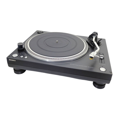
Sony PS-X75 User manual

SPECIFICATIONS
GENERAL
TURNTABLE
Power
Requirements:
240
V
ac
~
Platter:
adjustable,
50/60
Hz
(UK
model)
220
V
ac
~
Motor:
adjustable,
50/60
Hz
(AEP
model)
120
V
ac,
60
Hz
(US,
Canadian
mode!)
Drive
System:
110
—
120,
220
—
240
V
ac
~
adjustable,
50/60
Hz
(E
model)
Speed:
Power
Consumption:
18W
Dimensions:
Approx.
480
(w)
x
165
(h)
x
420
(d)
mm
19
(w)
x
61/,
(h)
x
16%
(d)
inches
including
projecting
parts
and
controls
Weight:
Approx.
13
kg,
28
Ib
11
oz
(net):
Approx.
15
kg,
33
Ib
2
oz
(in
shipping
carton)
SAFETY-RELATED
COMPONENT
WARNING!!
COMPONENTS
IDENTIFIED
BY
SHADING
AND
MARK
A
ON
THE
SCHEMATIC
DIAGRAMS,
EXPLODED
VIEWS
AND
IN.
THE
PARTS
LIST
ARE
CRITICAL
TO
SAFE
OPERATION.
REPLACE
THESE
COMPONENTS
WITH
SONY
PARTS
WHOSE
PART
NUMBERS
APPEAR
AS
SHOWN
IN
THIS
MANUAL
OR
IN
SUPPLEMENTS
PUBLISHED
BY
SONY.
ATTENTION
AU
COMPOSANT
AYANT
RAPPORT
A
LA
SECURITE!
LES
COMPOSANTS
IDENTIFIES
PAR
UNE
TRAME
ET
UNE
MARQUE
/\
SUR
LES
DIAGRAMMES
SCHE-
MATIQUES,
LES
VUES
EXPLOSEES
ET
LA
LISTE
DES
PIECES
SONT
CRITIQUES
POUR
LA
SECURITE
DE
FONCTIONNEMENT.
NE
REMPLACER
CES
COMPOSANTS
QUE
PAR
DES
PIECES
SONY
DONT
LES
NUMEROS
SONT
DONNES
DANS
CE
MANUEL
OU
DANS
LES
SUPPLEMENTS
PUBLIES
PAR
SONY.
US
Model
Canadian
Model
AEP
Model
UK
Model
E
Model
STEREO
TURNTABLE
SYSTEM
Speed
Control
Range:
Starting
Characteristics:
Wow
and
Flutter:
Signal-to-Noise
Ratio:
Speed
Deviation:
Load
Characteristics:
Automatic
System:
32
cm
(125/,
inches),
aluminum-alloy
diecast
DC
servo-controlled
linear
BSL
motor
Direct
drive,
crystal-lock
and
magneciisc
servo
control
system
331/,
rpm,
45
rpm
+10
%
(crystal!
lock
OFF)
Comes
to
nominal
speed
within
a
habf
revolution
(331/,
rpm)
+0.035
%
(DIN)
0.025
%
(WRMS)
78
dB
(DIN-B)
Within
0.003
%
0
%
at
tracking
force
up
to
150
g
(at
lead-in
groove
of
a
record)
Lead-in,
return,
reject,
repeat
record-size
selection
—
Continued
on
page
2
—
SONY.
SERVICE
MANUAL

PS-X75
|
TONEARM
Type:
Pivot-to-Stylus
Length:
Overal!
Arm
Length:
Overhang:
Tracking
Error:
Stylus
Force
Adjustment
Range:
Sheil
Weight:
Cartridge
Weight
Range:
(including
supplied
headshe!l)
Electronic
tonearm,
universal
235
mm
(91/,
inches)
330
mm
(13
inches)
13
mm
(%,6
inches)
+2°40',
—1°30'"
0-—3.09
11g
12-199
19
—
26
g
(with
extra
weight)
MODEL
IDENTIFICATION
—
Specification
Label
—
STEREO
TURNTABLE
SYSTEM
MODEL
NO,
PS-X75
SERIAL
NO.
US,
Canadian
model:
AC
120
V
60
Hz
18
W
AEP
model:
AC
220
V
~
50/60
Hz
18
W
MADE
IN
JAPAN
UK
model:
AC
240
V
~
50/60
Hz
18
W
E
model:
AC
110
—
120,
220
—
240
V
~
50/60
Hz
18
W

|
PS-X75
SERVICING
NOTES
Handling
Precautions
for
MOS
ICs
(1C103,
104,
107,
108,
110
—
112)
Generally,
the
insulation
resistance
of
the
oxide
layer
in.
MOS
IC
structures
is
very
high,
and
the
oxide
layer
is
very
thin.
Because
of
this,
it
is
possible
that
the
static
voltages
usually
present
on
clothes
and
the
human
body
will
be
enough
to
generate
a
potential
difference
across
the
insulator,
high
enough
to
cause
a
breakdown
of
the
insulating
layer.
The
following
precautions
should
be
taken
while
handling
these
ICs.
(Particular
care
should
be
taken
under
conditions
of
low
humidity.)
Precautions
in
Replacing
MOS
ICs
1.
Store
new
ICs
by
inserting
them
into
a
urethane-
polyester
cushion
(which
is
somewhat
conduc-
tive),
or
wrapping
it
in
aluminum
foil,
so
that
all
the
pins
are
at
the
same
potential.
(The
ICs
should
be
stored
in
that
manner
until
mounted
on
the
circuit
board.)
Fig.
A
partially
conductive
unrethane-polyester
cushion
1c
Fig.
B
aluminum
foil
2.
Check
the
soldering
iron
for
possible
power-line
leakage
current.
Make
sure
that
there
is
no
leakage
path
by
connecting
an
ohmmeter
to
the
tip
of
the
soldering
iron
and
the
plug
as
shown
in
Fig.
C.
If
there
is
a
leakage
path,
use
some
other
soldering
iron.
VOM
(2.x
10,000
range)
3.
Equalize
any
potential
difference
between
the
clothes,
the
tools
in
use,
the
work
bench,
the
set
being
worked
on,
and
the
packaged
IC
by
touching
them
all
in
succession
with
the
hands
or
a
conductive
wire
or
tool.
4.
The
following
are
effective
methods
for
handl-
ing
ICs
that
remove
the
potential
difference
across
the
oxide
layer.
@
Use
a
paper
clip
modified
by
soldering
in
a
wire
braid
insert.
wire
braid
soldered
soldered
:
Make
sure
that
there
is
Fig.
D
no
solder
on
the
inside.
clip
partially
conductive
"
urethane-polyester
Fig.
E
cushion
or
aluminun
oil
wire
braid
D>)
clip
(—=—~sossscsnssecsereor
es
aes
@aSabeas
ITT
Lt
Ld
hae
SXXEE
AEE
EES
Make
sure
that
all
the
pins
are
in
contact
with
the
wire
braid
{all
:
the
pins
will
then
be
at
the
same
Fig.
F
_
potential.).

PS-X75
®
Take
a
short
length
of
fine
bare
wire
and
wind
it
around
the
IC
so
that
it
shorts
all
the
pins
of
the
IC,
while
it
is
still
in
the
urethane-
polyester
cushion
or
aluminum
foil.
This
ensures
that
all
the
pins
are
at
the
same
potential.
fine
bare
wire
(stripped
solid
hookup
wire,
etc.)
partially
conductive
urethane-polyester
cushion
or
aluminum
foil
Fig.
G
@
When
it
is
necessary
to
handle
the
IC
with
the
fingers,
do
not
touch
any
pin,
and
hold
the
IC
at
the
ends
of
its
plastic-package
case
as
shown
in
Fig.
H.
Fig.
H
Method
of
Mounting
Insert
the
IC
while
holding
it
with
the
modified
clip,
and
solder
all
the
pins
with
the
clip
still
shorting
the
pins.
(Similarly,
solder
all
the
pins
while
the
bare
shorting
wire
is
still
wound
around
them.).
Remove
the
clip
or
the
bare
shorting
wire
only
after
all
the
pins
have
been
soldered.
Precaution
while
Checking
C-MOS
ICs
The
C-MOS
ICs
(Complementary
MOS)
are
MOS
ICs
that
have
their
output
sections
made
up
of
N-channel
and
P-channel
push-pull
stages
to
increase
their
speed
of
operation.
If
the
output
terminal
of
these
ICs
comes
into
contact
with
B+
or
B-
voltage,
then
the
FET
which
is
ON
at
that
time
will
either
become
shorted
or
open.
This
is
valid
for
all
the
output
sections
that
are
connected
together
by
the
interconnections.
Even
the
circuits
that
are
physically
separated
(and
not
on
the
same
board)
can
be
destroyed
simultaneously.
Example:
If
this
line
is
grounded,
or
touches
B+
or
B-
bus...,
the
output
stage
of
this
IC
will
be
destroyed.
Fig.
1

PS-X75
SECTION
1
OUTLINE
BLOCK
DIAGRAM
1-1.
WEE
2Hl-OllD
3Alud
037
ivadau
02
—
2020
WoLLDaL30-da4ds
=
~-033dS
-a
+9
—(pp
ane
EOIN
ISA
jean
Bs
AlN
O31
Bold!
101
‘90191
BATYd
YOLOW
dWV
OAN3S
IS-b0SS
HOW
90i—v0ld
HOLIMS
TOYXLNOD
934
JOVL10A
10S
£0!—
1010
1019!
934u
JOVLIOA
HHEOI
LENDUI9
20195
v0l—1010
YOSSIIONdOUIIW
rane)
ODI
9210
SNILAW
lei
—82io0
Oltdt
SAIN
SAtHa
MOLOW
431417
YOLOW
“YOH
2
WHV3NOL
WYV3NOL
YOSN3S
.
TOULNOD
hav
NOL
seas
30404-SNTALS
£O£-10E0
Cov
—10%0
Is
01
‘0101
Cy)
|
(*)
2010
130
NOILISOd
|
3AluG
33
bal
206
‘10SD
101d
Gel
‘pelo
Be,
CD
3ZIS
GHOdsy
e210
ONILAW
ge
1
‘210
60191
YOSN3S
WOILUSA
20s]
1091
0000
YYOQY
eel
‘1210
60191
JAIN
YQLOW
YV3NI1
WOIILYFA

PS-X75
|
1-2.”
ELECTRONICALLY-CONTROLLED
TONEARM
“BIOTRACER”
1-2-1.Resonance
Damping
at
Low
Frequencies
by
Speed
Feedback:
Tonearm
vibration,
particularly
the
resonance
generated
at
low
frequencies,
is
automatically
reduced
by
feeding
the
speed
fractuation
to
the
linear
motor
which
monitors
the
speed
of
the
tonearm.
1-2-2.
Front-panel-controlled
Stylus
Force:
To
set
the
stylus force,
turn
the
knob
on
the
front
panel,
and
the
built-in
microcomputer
will
measure
the
force.
Changing
of
the
stylus
force
while
listening
to
the
tones
is
also
possible.
1-2-3.
Remote
Full-Auto
Function:
A
luminar
sensor
controls
the
tonearm’s
lead-in
and
return,
while
monitoring
of
the
down
and
return-
ing
positions
is
carried
out
by
the
linear
motor.
Accordingly,
the
operation
is
accurate
and
virtually
silent.
1-2-4.
Tonearm
Lifter
Control
from
Front
Panel:
The
up/down
operation
of
the
tonearm
lifter
is
controlled
by
the
vertical
linear
motor,
and
the
damper,
fitted
with
a
speed
feedback
circuit,
operates
smoothly
free
from
the
effects
of
temperature
change
and
aging.
A
muting
circuit
operates
when
the
tonearm
is
in
its
top
position
and
because
this
function
is
cancelled
when
the
tonearm
is
down
on
the
turntable,
the
bother
of
having
to
lower
the
amplifier
volume
every
time
the
stylus
has
landed
on
the
record
is
eliminated.
1-2-5,
Fast
Repeat
Facility:
Repeat
operation,
controlled
electronically
by
the
horizontal
linear
motor,
begins
as
soon
as
the
tonearm
returns
to
near
the
edge
of
a
record.
1-2-6.
Manual
Operation
with
the
Dust
Cover
in
Place:
Manual
operation
is
throughly
possible
without
touching
the
tonearm,
since
the
upward/downward
and
rightward/leftward
movement
of
the
tonearm
can
be
done
by
buttons
provided
on
the
control
panel.
1-3,
TURNTABLE
AND
OTHERS
1-3-1.
Automatic
Record-size
Detection
Facility:
The
size
of
records
is
monitored
and
measured
by
using
a
photo-electric
device
and
a
built-in
micro-
computer
which
then
automatically
puts
the
tonearm
into
operation.
1-3-2.
Crystal-locked
Magnedisc
Servo
System:
The
turntable
driving
system
employs
the
es-
tablished
magnedisc
system
known
as
a
highly-
accurate
rotation
monitoring
and,
a
phase-locking
using
a
precision
output
frequency
generated
by
a
crystal
oscillator
to
obtain
a
constant
turntable
rotation
with
low
drift.
1-3-3.
Linear
BSL
Motor:
A
smooth
and
silent
rotation
is
obtained
from
the
Linear
BSL
Motor
—
almost
no
cogging
which
can
become
a
source
of
wow
and
flutter
or
S/N
degradation.
Having
a
high
torqueage,
the
starting
response
is
excellent
at
a
half
of
a
turn.
1-3-4,
Turntable
Incorporates
Electromagnetic
Brake:
Playing
of
records
is
easy
due
to
the
tonearm’s
independent
operation
and
the
simple
start/stop
Operation
of
the
turntable
rotation,
and
a
lead-in
to
a
music
is
done
very
easily.
Also,
with
the
electro-
magnetic
brake,
stopping
the
turntable
is
smooth
and
quick
as
well
as
simple
to
use.

1-4,
CIRCUIT
DESCRIPTION
1-4-1.
When
the
POWER
Switch
is
turned
on
(see
Fig.
1):
The
waveform
shaper,
consisting
of
IC111,
turns
the
voltage
at
terminal
(3)
of
IC102
to
low
level
“0”
in
half
a
second
during
which
C112
is
charged
with
B+
power.
Asa
result,
IC102
is
reset.
OV
Fig.
1
S501
(POWER}:
ON
1-4-2.
Arm
Lifter
Raising/Lowering
Circuit(see
Fig.
2):
Turning
the
power
switch
on
raises
the
arm
lifter.
[Lowering
the
arm
lifter]
When
S508
(UP/DOWN)
is
depressed,
the
voltage
at
terminal
(24)
of
IC102
becomes
high
“1”.
This
turns
the
voltage
at
terminal
(6)
of
IC112
to
positive
and
the
voltage
at
terminal
(7)
to
negative.
Asa
result,
Q131
switches
on.
The
potential
of
the
terminal
(2)
of
IC112
now
becomes
negative
and
the
output
of
the
terminal
(1)
goes
positive.
This
turns
Q128
on.
|
aa
OV
ARM
LIFTER
DOWN
Fig.
2
-—-7-—
|
PS-X75
This
means
that
the
microprocessor
(IC102)
does
not
operate
for 0.5
seconds
after
the
power
switch
is
turned
on.
Also,
buttons
can
be
effectively
pressed
after
it
is
assured
that
the
tonearm
has
been
on
the
arm
rest
for
about
0.5
seconds.
S501
(POWER):
ON
rn
IT
Since
both
Q128
and
Q131
are
on,
current
passes
through
L505
(lifter
drive
coil)
in
direction
A,
thus
lowéring
the
arm
lifter.
[Raising
the
arm
lifter]
When
S508
is
depressed,
the
voltage
at
terminal
(25)
of
1C102
becomes
high
“1”.
This
turns
the
voltage
at
terminal
(7)
of
IC112
to
positive,
switching
Q130
on.
Since
Q130
is
on,
a
negative
voltage
appears
at
terminal
(1),
turning
Q127
on.
Now
that
both
Q127
and
Q130
are
on,
current
passes
through
L505
in
direction
B,
thus
raising
the
arm
lifter.
ARM
LIFTER
ARMLIFTER
DOWN
ARM
LIFTER
ARMLIFTER
DOWN
uP

PS-X75
|
1-4-3.
Tonearm
Swivelling
Circuit
(see
Fig.
3):
Turning
the
power
switch
on
returns
the
tonearm
to
the
arm
rest.
[
>
:
BACK]
When
S507
(
>
:
BACK)
is
turned
on,
the
voltages
at
terminals
(17)
and
(18)
of
IC102
become
high
“1”.
This
turns
the
voltages
at
terminals
(6)
and
(7)
of
IC110
respectively
to
positive
and
negative.
<A
negative
voltage
then
appears
at
terminal
(1)
of
IC110.
FORWARD
1-4-4,
Tonearm
Lifting
Circuit
(see
Fig.
4):
When
the
arm
lifter
is
lowered
in
the
zero
balance
are,
Q108
turns
off
because
the
voltage
at
terminal
(20)
of
IC102
is
high
“1”.
As
a
result,
varying
RV502
(STYLUS
FORCE:ANTI
SKATING)
causes
no
change
in
the
stylus
force.
However,
since
the
voltage
at
terminal
(23)
of
IC102
becomes
low
“0”,
a
positive
voltage
appears
at
terminal
(1)
of
I1C109,
turning
Q121
on.
This
causes
current
to
pass
through
L501
(vertical
drive
coil)
in
direction
A
and
lifts
the
tonearm.
This
function
helps
apply
a
constant
stylus
force
when
the
tonearm
is
moved
forward
or
backward,
thereby
preventing
the
arm
from
deflecting.
Also,
since
the
voltage
at
terminal
(26)
of
1C102
becomes
low
“0”,
Q133
turns
off.
This
lowers
the
gate
voltage
of
Q132,
resulting
in
no
MFB
current
which
would
otherwise
generate
in
L502,
with
the
movement
of
the
tonearm.
When
the
arm
lifter
is
Fig.
3
As
a
result,
Q125
turns
on
to
pass
current
through
L503
(horizontal
drive
coil)
in
direction
A,
returning
home
the
tonearm.
[<d:
FORWARD]
When
S506
(<:
FORWARD)
is
turned
on,
the
voltages
at
terminals
(15)
and
(16)
of
IC102
become
high
“1”,
This
turns
the
voltage
at
terminal
(1)
of
IC110
to
positive,
and,
consequently,
switches
Q124
on.
Now
that
Q124
is
on,
current
flows
through
L503
in
direction
B,
moving
forward
the
tonearm.
lowered
outside
the
zero
balance
area,
Q108
turns
on
because
the
voltage
at
terminal
(20)
of
IC102
becomes
low
“0”.
Asa
result,
varying
RV502
causes
voltage
ranging
from
0
to
5
volts
to
be
applied
to
terminal
(6)
of
IC109.
A
negative
voltage
then
appears
at
terminal
(1),
turning
Q122
on.
Now
that
Q122
is
on,
L501
has
current
pro-
portional
to
the
stylus
force
in
direction
B.

5V
ov
ie]
ARM
LIFTER
DOWN
|
PS-X75
Bt
=
Q108
UT
OF
ZERO
BALANCE.
ST
@
0
1)
STYLUS
FORCE
Og7>39
ae
Tepe
at
avaoe
TO
HORIZONTAL-
[-D
9
DRIVE
CIRCUIT
FSO
=
Bt
1C109
er
ce
oO”
sas
@-O-}>-O+Omn
|
|S
aie
ote
a.
Mma
bd
2]
&
1502
iaioe
al
Com
&
7
B
STYLUS
FORCE
2
9
Q122
NE
39
Bt
<I
0133
eae
er
BALA
@
©)
Le
6)
tO)
i>
Q132
5
Vv
\
ci
_
1C102
oie
1C103
kay
WITHIN
ZERO
;
B-
BALANCE
Fig.
4
(ARM
LIFTER
DOWN)
1-4-5,
Automatic
Disk
Size
Detector
(see
Fig.
5):
As
long
as
the
turntable
is
rotating,
the
light
from
PLS501
passes
through
the
prism
on
the
turntable
mat
and
switches
phototransistors
Q501
and
Q502.
The
outputs
of
Q501
and
Q502
are
fed
to
termi-
nals
(30)
and
(31)
of
IC102
to
be
used
for
automatic
detection
of
the
disk
size.
when
no
record
placed
—--~
SS
when
a
record
p+
placed:
OV
when
no
record
___
placed
i
[|
|
OV
when
a
record
placed:
0V
[Nodsk
|
1
|
St
*d
Cn
Ee
ee
ee
ee
ee
e
when
a
record
plaed:
0
when
no
record
paced:
7
Q502
PL501
Le
B-
Fig.
5

PS-X75
1-4-6.
Drop-point
and
End
Detection
(see
Figs.
6
and
7):
When
S504
(AUTO
START)
is
turned
on,
the
tonearm
moves
toward
the
disk.
The
presence
of
a
drop-point
on
the
disk
is
deter-
mined
by
counting
slits
of
the
movable
shutter
ro-
tating
with
the
tonearm.
The
end
of
a
disk
is
also
detected
by
counting
slits
of
the
movable
shutter.
After
detecting
the
end,
the
tonearm
returns.
Slits
are
counted
as
follows.
The
light
emitted
by
D401
and
D402
strike
on
the
movable
shutter.
If
the
light
from
D401
(D402)
passes
a
slit,
it
turns
on
Q301
(Q302).
The
outputs
of
Q301
and
Q302
are
fed
to
the
Schmitt
circuit
consisting
of
IC103,
where
the
waveforms
are
shaped.
The
shaped
outputs
are
applied
to
terminals
(32)
and
(33)
of
IC102.
Also,
whether
the
tonearm
is
moving
forward
or
backward
is
determined
by
comparing
the
phases
of
the
signals
from
terminals
(32)
and
(33)
of
IC102.
fixed
slitA
—
—_
phase
difference:
90°
slit
of
movable
shutter
—_—
=
fixed
slitB
slit
B
|
|
|
|
| |
| |
|
|
{FORWARD)
slitA
|
|
|
| | |
| |
|
|
slitB
| |
|
|
|
|
|
|
|
|
|
(BACK)
D401
D402
Fig.
7

PS-X75
PS-X75
1-4-7,
Waveforms
1cl04
ieee
Pear
(
O@
RS
O
NAMA
@~D
oes
sv
©
.
@sv
@@
ow
@
sv
—
@
v-——_-—_.
FR
A
iV
-5V~-15V
/
ov
@av
SV
3509
[REPEAT
$507
(B]
aack
on
as
WITHIN.
ZERO~
THN
ZERO
\
os
TM»
LUE
@
29
—
aa
eo.
ea
Wi
Sat
/
Vv
"
ul
iN
WITHIN
ZERO
BOT
OF
PERO
/
@
sv
ov
°
e
oy,
@
ocsv
TONEARM
LIFTER
av
———__
©@
Canes
|
11
0.5sec
9.5msec.
Ov
*
OV
@
DOWN
@
ov
_—
®
sv
@-@
ov
$506
EFwo
a
aM
SS
@
sv
ov
"yRATABLE
MOTOR
ON
@
sv
$503
(DOWN)
ON
ov
z
®
sv
@
sv
ov
TONEARM.
LIFTER
—
~18v
POWER
”
Rowen
‘i
ay
\
ov
ee
;
a
LIFTER
Down
=
@_
Sv
—eEEE
DOWNED
oy
edt
tT
\
33rpm
45rpm
i
OUT
OF
ZERO-
TONE
POWER!
*
TFONER
:
:
$506
J
Fwo
BALANCE,
TONEARM
oy
7
2PM
SVINGING
—-
:
-
on
RIFTER
OWN
$502
(UP)
ON
@~®
4v
(STYLUS
FORCE
APPLIED)
TONEARW
Lif
TER
j
{CONTROL
BOARD!
TONEARM
LIFTER
UP
FULLY
LPPED
ov
|
—_-
a
ao
oe
.
:
Fara
ee
0202
—
204
sLP248
Iet0g,
x193
115,
2gAB36
O15,
ec
ises
O14
28C1364_Q110”
2SC1366
UCONTROL
BOARD
1
MER
aca
reat
[70201,208
FUNC
33¢pm:3,
ONT
2sC1364
112
-2sC1364
,
BUTTON
KEPT
OMY
ee.
OY
N1_
2SC1364
ON2
250136:
1
SLP24B
[LOCKED]
Beene
seo
5
1
0.8V
git
y
} J
aX
[oz
,
33rpm:
3.5msec
Cf,
ta
45rpm:
2.7msec
0501
502
gy
atv
'
Ls
oe]
HGH
INPUT
OV
<4
0.IVp~0
COLLECTOR
“Te
hee
sm
ov
cs
ico?
©
0134,
135
*
TOC
—
my
BASE
poe
a
a
|
Qué
en
oe,
0o
tog
OY
Se
te
200-9
2.8
2a
SEES
1106
@)
1
25v
=
i
(0.6Vp-p
AT
PERO
Tn
TEE
\
ne
LIFTER
UP
LiTER,cowN
aes]
ONG
=
is,
72
|
ere
013.114
Tao
/
Se
i
:
v
;
TOR
B45”
ato?
2sc1364
|
oe
tS
Ov
LED
ORE
|
Yel
@
Ney
Sar
ano:
1200
4
See
5~
10%
2Sa755
KS
WITHIN
ZERO-
WITHIN
ZERO
eae
papataom
BALANCE/TONEaRM
BLLANCE”TONEARU
ieTeR
COM
7
LIFTER
UP
uae
POWN
cryryg
@
wv
=e
ee
H
Force
09
——>
39
t
oky
}
:
ov
—
-———_——
icl03
Oey
‘
@®
ov
t
©
2V
==—
:
t
3.5V
i
~o.7y
|
ER
SE
YP
-
-
—
~
ee
’
f
NI]
1601
ne
—tF
1
;
7
tv
%
.9501
0502
0108
2SA83K
®
ov
a
:
PRO
PHIOI
Ditntt2
1740
Ll
rane
eose
@
ven
\
S379
16109
yPC4SSB0FA
LNEAR-woToR
OAVE
a4]
-
!
602
-
:
-5
av\
3ALA
j
0123.
28¢1366
ar
aan
Ae
i
‘
oN
\
rin,
so
ayso2
ae
-
masts
22k
2.5ysec
?
pee
Move
\
0g
—=3
tio
f
@
ov
Not
Noy
ay
Ue
TS
Pe
'
1c102
1
D280
GRIRSASESS
HH
0-
"
a
4
m88841-209L
,
Ne
“toe
|
CROOOMPUTER
\
ov
es
-5V
aree
Bes
ine!
TONEARM
RESTED
TONEARM
RESTED
"ays
Ag
ON
ToNeaRM
REST
[I
ee
e
®
zw
j
(STOP)
(FORWARD)
(STOP) (BACK]
(STOP!
ek
one
16196
grCenoe
oe
oy
i
it
Icl10
H
;
t
:
i
arzt
Be
x
i
Git
OTOR
ORE
RIG
cab
0067
—
@®,,
-o4v
OW
ov
-0.05v__-0.4v
asvaie
ay
!
\
\
@
Bmsec
ov
Sl
SS
Ra
aac
DED
122,125
ery
WITHIN
ZERO-
i
|
\
\
@
fot
i
288548
30?
ov
\
}
2IV—
-
t
\
‘
vata
&
|_
BALANCE
/
TONE
ARM
\
\
|
an
'
av
‘
'
’
vse
Tes
LIFTER
DOWN:
Cv
|
@.8msec
\
\
ii
Cc
ov
-sv
-0.5V
0
-IV
=5V
0132
2:
22k
—
:
.
Se
a
<a
roma]
|
tet
rf
\
znse
|
'
{
-
mas
0133
2sAge4
0
:
101
2sciaig
J
‘
nS
:
by
-o02v
ov
0.04
a
a
Swng
.
|
BR
i
i
ae
foe
quot
2sc14t
,
ic108
o)
MO
@O®©
ov
—
ae
'
ols
TON
TE
——_
6Vp—
®
1
CONEARITCRTER
a9
;
9102,
103
7”
’
t
{
1
Hf
SS
0124
Bo
DOWN
*
5V
2sc945
%
5)
gy
av
bv
2
~~
Bm
‘i!
—
———
ae
rene
\
Olly
@
ov
=
~.
“ar2s
28860:
ie
>
-
s
118
we
Frame
am
oe
es
Se
=
—
“\
EMITTER
pees
ot
i
Bs
PO
.
Was)
220k
otis
Ov
a
7
4Vp—p
2
ee
.
256
68
TONEARM
LIFTER
¢
ok
lease
\
a
+
+++
Zo
ee,
=
TONEARM
LIFTER
TONEARM
LIFTER
FULLY
DOWNED
TONEARM
LIFTER
TONEARM
LIFTER
=
+
wan
fe
aa
Ls
Sai
EwITTER
2
J
Tonearm
uirter
UPPING
FULLY UPPED
senate
ET
Se}
||
fin
Gian
tim]
paTOr—
ons
\
|
ba
a
(raves)
ov
div]
ov
DOWN
-002v
-O.l4v
Stason
©
Yt
a
"ou
[te
ts
.
49
@
ow
. i
2.
:
~_“apsoz
HZ6AL1
\
|_|
7
Ts
cA
m
fray
weil
$250
gp
7
,
|
ov
ff
t
a¢
L
‘seer
:
e126
2SC1364
a
WITHIN
ZERO~
i
aM
y
901
2.05v
'
BOARD
-
|
Dad
‘
BALANCE
/
TONEARM
.
®
ov
—
ces
—0.02V_~006v
Gide
eeena
ia
1c110,112_
pPC45S7
LIFTER
DOWN:
5V
-_—
=
acbay
#
ac
N
©
sf]
rl
LINEAR
MOTOR
DRIVE
one
= 2
fODSY
2S
F
i
0129
2sas4a__J
|
oss
i
ssn
|
|
:
8
0
5Sec
oom
|
upd
107,108
D101—104
®
'
Yyete-MOTOR
erence
a
vax
4
’
Ic
TC1050
1T40
$1B01-02
;
=
-
2
_
RESET
roe
t
i
;
a0
esver4—||
4
oy
'
9105,106
Be
css
[ese
pate
gia
we
0104,105
25a
a
131
2se548
fiev
Dev
)]
piso
Sue
aceon
cares
106
2SA755
Z)
ee
a
——*
(PE
ad
saan
Fig.
8
;
—12—
|
SONY-00893
/
DRUCK
1

SECTION
2
DISASSEMBLY
*
Turntable:
@
Lift
up.
*
Dust
Cover:
@,
©
Lift
up.
*
Bottom
Plate:
O-
@
Remove
screws.
dust
cover
—
turntable
mat
turntable
Note:
For
the
tonearm
section,
refer
to
the
exploded
SONY-00893
/
DRUCK
2
view
(3)
on
page
26.
Note:
Be
sure
not
to
scratch
and
hurt
the
magnetic
conductor
coated
on
the
inside
wall
of
the
turntable.
turntable
magnetic
conductor
PS-X75
PS-X75
|
3-1.
MECHANICAL
ADJUSTMENTS
SECTION
3
ADJUSTMENTS
Solenoid
Position
Adjustment
1.
Loosen
the
adjustment
screws.
2.
Adjust
the
positions
of
solenoids
so
that
the
clearances
A
through
D
become
A
=
B
and
C=D
as
shown.
magnets
Eee
ell
==
ll|
ZZ
|
oa.
adjustment
screws
solenoid
solenoid
ye
adjustment
screws
3.
After
the
adjustment,
tighten
the
adjustment
screws.
Vertical-sensitivity
Adjustment
1.
Perform
the
longitudinal
adjustment.
2.
Adjust
the
pivot
bearings
and
the
pivot-locking
nuts
so
that
the
tonearm
sinks
more
than
5
mm
(Ys2
inches)
when
the
40
mg
weight
is
placed
on
the
head
shell,
and
the
tonearm
is
in
a
horizontally
balanced
position
when
the
weight
is
removed.
Note:
Tighten
the
pivot
bearings
as
shown
below.
more
than
§
mm
(7/32)
Stylus
Height
Adjustment
1.
Bring
the
tonearm
above
the
record.
2.
Lift
the
cueing
lever
up
and
make
sure
that
the
clearance
between
the
stylus
tip
and
the
record
is
5—9
mm
(7/32—4
inches).
5-—9mm
(Ss2—-F0
—
SS
==
record
3.
If
necessary,
loosen
the
adjustment
screw
(M3
x
3)
and
adjust
the
arm
lifter
height.
Coil
Plate
Position
Adjustment
1.
Adjust
the
coil
plate
position
so
that
the
movable
shutter
does
not
touch
the
detection
part
when
the
arm
pipe
is
moved
horizontally.
circuit
board
holder
(B)
position-detecting
board
coil
plate
movable
shutter
Position-detecting
LED
board
circuit
board
holder
(A)
L-shaped
wrench
movable
shutter
er
1.5mm
L-shaped
wrench
Ot
7.5mm

3-2.
ELECTRICAL
ADJUSTMENTS
PS-X75
PS-X75
|
Drop-point
Adjustment
Tonearm
Horizontal
Motor
Offset
Adjustment
Speed
Adjustment
Speed-
1.
Set
RV501
to
the
mechanical-mid
position.
1.
Secure
the
tonearm
on
the
arm
rest.
1,
Set
the
SPEED
to
45
rpm.
6.
Confirm
that
the
LOCKED
indication
is
lighting
i
2.
Adjust
RV103
so
that
the
stylus
drops
on
the
2.
Connect
an
oscilloscope
to
TPS.
2.
Connect
an
oscilloscope
to
TP8.
up.
-
Seti
: | ;
oscilloscope
2.
Con:
specified
point
of
the
test
record.
3.
Push
the
ARM
TRANSPORT
(VY,
w)
button
and
3.
Adjust
RV106
for
a
waveform
as
shown
on
45
rom
|
|
|
|
on
move
the
arm
rest
up
and
down
several
times.
the
right.
150—250
usec
3.
Pusk
=
}
turn
|
Teetcsvard_
[_—Soant
ot
erop
pen
4,
Adjust
RV111
to
make
A
and
B
shown
below
4.
Set the
SPEED
to
33
rpm.
Pere
|
|
al
z
5
.
Adj
eaual
pila
5.
Adjust
RV105
for
a
waveform
as
shown
on
a
ig
450—550
usec
that
the
right.
ae
3.
When
RV5O1
is
turned
clockwise,
the
count
of
drop-point
should
be
smaller
than
the
specified.
Slit
A
and
B
Adjustments
Ere
1.
Connect
a
dual-trace
oscilloscope
to
TP6
(for
slit
aad
B)
and
TP7
(for
slit
A).
sil
Gh
os
.
Conn
2.
Push
the
ARM
TRANSPORT
button
<j
(forward)
terminal
©)
or
>
(back)
and
swing
the
tonearm.
3.
Set
tk
3.
During
the
tonearm
swinging,
adjust
RV102
(slit
4.
Throv
B)
and
RV1O01
(slit
A)
to
obtain
the
square
waves
RVIC
as
shown
below.
5.
Throw
4.
Push
the
ARM
TRANSPORT
button
<I
(forward)
dual-trace
|
RVIC
or
>(back)
and
swing
the
tonearm.
aacillaxcoe
;
y
ok
pe:
6.
Thro
5.
Move
the
position-detecting
board
for
the
phase
RV11
difference
shown
below.
wavef
7.
Throv
.
RVIC
Stylus
Force
Adjustment
a
wav
TP6
(slit
B)
1.
Set
the
STYLUS
FORCE
control
to
3
g.
2.
Adjust
RV104
so
that
the
tension
gauge
reads
3
g.
3.
Set
the
STYLUS
FORCE
control
to
0.5
g.
Con-
firm
that
the
tension
gauge
indicates
0.5-g.
position-detection
board
TP7
(slit
A)
cartridge
tension
gauge
—15—
=—T6—
SONY-00893
/
DRUCK
3

5-X75
‘ton
and
1
times.
1
below
lloscope
_
ie
+0
PS-X75
Speed
Adjustment
1,
Set
the
SPEED
to
45
rpm.
6.
Confirm
that
the
LOCKED
indication
is
lighting
up.
oscilloscope
45
rom
|
|
|
|
150-250
usec
Speed-detecting
Head
Output
Level
Adjustment
1,
Set
the
SPEED
to
33
rpm.
2.
Connect
an
oscilloscope
to
TP8.
3.
Adjust
RV106
for
a
waveform
as
shown
on
the
right.
4.
Set the
SPEED
to
33
rpm.
5.
Adjust
RV105
for
a
waveform
as
shown
on
2.
Connect
a
VTVM
as
shown
below.
3.
Push
the
MOTOR
ON/OFF
button
to
rotate
the
turntable.
Sopm
4.
Adjust
the
position
of
the
speed-detecting
head
so
that
the
VITVM
reading
is
20
mV
ac
to
50
mV
ac.
Note:
The
clearance
between
the
magnet
coated
rim
and
the
speed-detecting
head
should
be
more
than
0.3
mm.
adjustment
VTVM
Screws
450—550
usec
terminal
@
Turntable
Motor
Adjustment
1.
Make
an
adaptor
for
adjustment
as
shown
below.
:
iy!
a
yy
pe
,
3
terminal
@
2.
Connect
a
VTVM
and
an
oscilloscope
as
shown.
3.
Set
the
SPEED
to
33
rpm.
4.
Throw
the
switch
to
terminal
G)
and
adjust
RV108
for
a
4
Vp-p
reading
on
the
oscilloscope.
5.
Throw
the
switch
to
terminal
©)
and
adjust
RV107
for
a
4
Vp-p
reading
on
the
oscilloscope.
6.
Throw
the
switch
to
terminal
G)
and
adjust
lengthened
for
‘
RV110
for
a0
V
dc
reading
on
the
VTVM
or
fora
easy
observation
ss
mss
-anaresete
esses
eres
sone
ee
irene
ind
etre
psc
waveform
as
shown
right.
7.
Throw
the
switch
to
terminal
©
and
adjust
RV109
for
a
0
V
dc
reading
on
the
VTVM
or
for
0
AE
(4)
ye
Stylus
Foree
Adjustment
a
waveform
as
shown
right.
—
2 &
1.
Set
the
STYLUS
FORCE
control
to
3
g.
2.
Adjust
RV104-so
that
the
tension
gauge
reads
3
g,
3.
Set
the
STYLUS
FORCE
control
to
0.5
g.
Con-
firm
that
the
tension
gauge
indicates
0.5-g.
ground
cartridge
adaptor
for
adjustment
tension
gauge
<T6=
—-17-
SONY-00893
/
DRUCK
4
|
PS-X75

110V—120Vexp220V—240V
Replacement
Semiconductors
A104,
105,
!
-
Q106,
118,
-
Q122,
125
_
Q121,
124
Q122,
125
Q132:2SK30A
§Q501,502:PH101
1C102:
MB8841-209
1C104,
107,
For
replacement,
use
semiconductors
except
in
(
108,
115,
|
120:
2SA671
(US,
Canadian
(AEP,
UK
model),
(AEP,
UK
model),
:
108,
110,
SECTION
4
133-135:
1
(2SA755)
model):
2SB605
128,
130:
Q129,
131:
-
ra
112:
uPC4557C¢
101,
117,
102,
103,
0121,
124
2SA1027R
|
:
28D414
2SB548
:
ion
Z
|
1109:
NJM4558DF,
119:
2SC1061_
107,
(US,
Canadian
(2SA733)
’
|
(2SA733)
letter
side
s
DIAGRAMS
(281419)
109-114,
model):
2SD571
EY.
,
ie
eee
ee,
azss
116,
123,
a
oe
boats
etree
4-1,
MOUNTING
DIAGRAM
pi
c
126:
2SC1364
c
|
c
eds
~~
{Ky
ner
CE
TTT
_&¥
|
____
1€103:
msm4o69
‘al
—
Conductor
Side
—
ip
(Ky,
_((2sce34a)
ny
+E),
kK),
!
Ky
fly
|
|
é
1C101:
uPC78L05
(TC4069UBP)
Raat
a
|
l
HH
.
c
deh
PANS
pels
on
ae
ns
14131211109
8
ecf
CY,
ig
.
1234567
ve
écy
:
123
“
(Top
view)
wiki
SERS
DROP-POINT
-
,
Ca
Nuno)
oes
ee
4
RE
—
SIZE
DETECTION
Li
SOR
Q502
4
/
HEAD
SHELL
:
E
MODEL
E
COIL
HOLDER
-
O.5SEC
Q50!
=
syecteal
ov
—
—
0}
Saitek
|
Saeko
VOLTAGE
SELECTOR
(IN
TONEARM)
ON
OFF
5
CDOWN-SWITCH
BOARD}
@
O~—
:
parts
extracted
from
the
component
side.
A
)
.
:
B+
pattern
Ps
OIL
HOLDER
:
nonflammable
resistor.
CONE
HOLE
SONY-00893
/
DRUCK
5
$502
(LIFTER
UP)
(~)—
SS5I2(MUTING
}
OT
—12.9
99909
099]
SIs
bib
oy
8
ov
DURING
MOTOR
:
ROTATING
{CONTROL
BOARD
3
107
122
126 124
125
12!
1cl09
1C104
133
iclo2
131
128
ICO
23
130129
jene
2
135,134
0
Ig
203 204
205
201

-
Q106,
118,
120:
2SA671
(2SA755)
he
ZX,
Q502
501
ERTICAL
JRIVE
SONY-00893
/
DRUCK
6
Q122,
125
(US,
Canadian
model):
2SB605
c
©)
E
EC
8
>
Biking
Toner
@ 3
TO)
Sane
(arcs
O.5SEC
SWITCHED
ON
sv—y
ov—
POWER
POWER
‘SWITCHED
OFF
Q121,
124
(AEP,
UK
model),
(AEP,
UK
model),
Q128,
130:
2SD414
letter
side
4
Q122,
125
Q129,
131:
2SB548
letter
side
c
8
&
id
|
&é
ce
1C102:
MB8841-209
Q132:
2SK30A
Q501,
502:
PH101
E
‘0301-303:
PH102
---—.—-£
:
1C101:
uPC78L05
(TC4069UBP)
c
>
€
1413121110
9
8
1234567
129
:
(Top
view}
;
AAAAE2v
©CPO00007D
00
0{CNIE
$/CWS510900/000009
4.5v—,
3v—'!
NN
‘
ov
—______—_
es
OURING
MOTOR
QURING
TONEARM
ROTATING
{C103
132
131
128
130129
ic1i2
122
(26
124
125
(l2i
(clog
Icio4,
(cl
CHO
Cc.
4
”)
2
6:
bo
1
5
©
$6
Oo
ee
eis
he
ee
ep
c
10103:
MSM4069
ov—_—_————$———_
‘4
REPEAT]
an
BR
GRY
[|
reo}
wut
Rw
YEL
SaaS
ERSNS
=
ay
ie
1104,
107,
10106:
CX193
Wa
uPCA5S7C
Matar
igii7
118113
10109:
NUJM4558DFA
[tata
6765
es
CSCS
CTE
Sr01102
aes
(Top
view)
Frog
tiaed
1C111:
TC4050BP
(MSM4050)
16151413121110
9
“12345678
(Top
view)
2.5V.
2.5V-—;
|
|
ov—
ov
D101—104:
10E2
(S1B01-02)
D105,
106:
HZ7B2!
D107-—109,
111-114,
116,
117:
1S1555
D110:
RD3.9E
D115:
HZ6A3L
(HZ6A1L)
cathode
Vv
33rpm
D201—205:
SLP24B
STYLUS
FORCE
ov—____-____—
ANTI
SKATING
|
45rom
5V
(el
(]
(BACK)
(FORWARD)
135,
134
203 204
205
IC10l
D401—403:
TLR123
2
long
sete
a
OOO
as
ety
0601,
602:
5GFMS-07F
marking
side
4
TURNTABLE
i
pee
ELECTION
|
33rpm
3.5mSEC
45rpm
2.7mSEC
O.1Vp-p
icloe
"9
102
101
107
RED
(AEP
MODEL)
VIO
(UK
MODEL)
V10
(AEP
MODEL?!
RED(UK
MODEL)
(]
AC
IN
120V
60H
=]
T501
POWER
|
|
Sa
renee
ke
et
rhe
eee
|
106
101, 102,
103,104

4-2.
SONY-00893
/
DRUCK
7
SCHEMATIC
DIAGRAM
CMAIN
BOARD
3
igi
saison]
-
LIGHT
SENSOR
[ave
Sut]
C103
TC4049
SHAPER
OARD
RVIOIL
2001
9301
9302
Aisi
PH102
-
PHI02
|
|
22k
oY
s
es
Aone
DURING
TONEARM
ove
UL
2
10k
—
SWINGING
RIS6
IM
SWINGING
DROP—
POINT
D109,
116
CONTROL
BOARDJ
|
RVSOI
1
50KB)
[PpsmON
bere
R158
22k
LIGHT
SENSOR
BOARD
4
B
'
ITION—
~
o-0
ries
OV
1C104
pPC4558
(takes
co
|
gi.”
Se
re
z
4.
$13
tana
Sp
Rig?
10%.
eee
lset
03
o4o1—403
“®)
|
TLR
123
050!
ATTOMATIC
!
we
LIGHT
SENSOR
J}
0501
Ty
Q108
2SA83K
BOARD
RIGO:
[]
at
URING
MOTOR
ROTA
ov
S
Z
A
std
aure
fis41352sae44
conic
cj29
ie
1M
aN
wsov
-RIZ3
7
ry
126
DURING
MOTOR
rirge
OM2
bin
shi75
Ov
ROTATING
i00k
gat.
Q502
5V
PH101
PH101
0111,112
1740
ANTI
SKATING
Tweanmorony
0121
280571
122
288605
/
Us
i
Fivow)
\
MODEL
EP,
UK)
Q121,124
i
SO.
MODE
L
280414
i
Q122
125
3
|
“asB548
verte?
E
.
Fj
SENSOR
[©
Q132
2SK30
SWITCHING
Q133
2SA844
SWITCHING
{
Al
\e
Q124
«2SD571]
1
Q125__
2SB605,
unerwor|
S
!
UP-SWITCH])
cme
i
i
BOARD
~
gL
$2?
_|
Q126
2801364
MUTING
L505
UFTER
ORIVE
LLL
LT
|
t
—
4
(2)
LINEAR-MOTOR
iD
R266
?
Boy
S
>
200k
LI
0130
,
(sy
253
0130
280414
Spite
#270
<S
is,
000
et)
fh
R269
C155,
10
4.7K
Q131
298548
,
te:
”!
7
a
eh
J
Qi3t
L506
LIFTER
SENSOR
a
_|
1¢110,112
_pPC4557
Q128
280414
|
CB
ie
LINEAR-MOTOR
ORIVE
iF
0129
2SB548
7
eee!
PS-X75
ov
{CONTROL
BOARD]
a
Aw
ty
pr
C3
eG
D202
10204
203
Cy
330
R213
R214
R215.
Ov,
[lOk
—
RZ
350k
(2)
C144
1OsI6V
pPC4557
LIMITER.
AMP
RV
sen:
3y
—INNNNS
OV
———_—_—___.
RING
MOTOR
Borat
Q
$503
oA
DOWN
| 4
[pga
(soa
BOARD
awn
7
His
[Freee
Ser
sowol
oiVp—p
0202
—
204
SLP24B
|
ERE
cro
of
|
ERVO
AMP
MGH
4
0L04'
ON
ama
any
RAM
128-4BiT
Tl
PS-X75
35rpm
3.5mSEC
45rpm
2.7mSEC
45rpm
5V
Cx193
0115,
aehS36
mr
O16
0114
ps
0107,108
1C111
TC105D
1T40
RESET
o\
UP
1
hie
Se
[RG
tosis
ae
eh
1.250
>
Wa
SV
ov
33rpm
28Vp-p
ov ov
QNY
2501364
FILTER
aa)
Roy
le
bs
A
(22V)
:
5
TURNTABLE-
MOTOR
GAIN
ete
Qi10
2sc1364
(CONTROL
BOARD
I
[70201,205
2sci3zed
sy
,
SLP24B
Q114
2501364
SWITCHING
Q1f1
2801364
Q112
———————
LOCK:
INDICATOR.
DRIVE.
Q114
470(1/2W)
mT
YO
|
R206
R207
10k
10k
Or)
cise
RIBS
a
63v,
®
0.04
yu
|
"6.87
£10k
Q117,119
4
aa
ORIVE,
Q118,120
1
2SA755
E
MODEL
Ic108
pPC4558
MOTOR
DRIVE
Q101
2801419
-
VOLTAGE
REGULATOR
Q102,103
280945
VOLTAGE
.REGULATOR
IC
101
pPC7BLOS
VOLTAGE
REGULATOR
ozo
y
(fix
weed
$O033/125V
4}
(CANADIAN.
MODEL).
op
PE
US
MODEL
Pe
0101—104
$1801-02
C108
105,106
He
HZ7BL2
HOv-t20v-e220v-240V
104,105
25836
VOLTAGE
REGULATOR
Q106
2SA755_
VOLTAGE.
REGULATOR
$50)
[POM
iy

'S-X75
PS-X75
|
35rpm
3.5mSEC
of
45rpm
2.7mSEC
Fe
|
\
[
\ [
\
1.280
Se
—-
o
VS
“TVV1
tpm
oiVp—p
28Vp-p
OV.
ov
ov
(CONTROL
BOARD}
45rpm
5V
-—_
-
-
ar
=
=
ioe
DeCiaaa
OO.
LCONTROL
BOARD}
D202
—
204
SLP24B
LE
cron
96
cX193
0115,
agAB36
Qn
euiepe
1304
Qit4
ZSCISES
Q110
28C1364
sea
|
=
Q111
2801364
Q112
2801364
5V
SLP248
Oe
i
aaa
i
ae
ome
0
4
wy
wee
te
Og
J
AE
eat
ee
Ny,
V4
Ov,
10k
R215.
3
pas
SV
(50)
—X2)
IX
EX
ES
;
OV:
()-—
(i)
ar
ow
ae
PC4557
Searce
sue
113,114
1T40
Q117,119
1
se
Ww
R142,
22k
°
Leo!
INSTRUCTION
DECODER
MOTOR
ORIVE
5V
R254
3.3,
ree
IC
101
pPC7BLOS
++——H
VOLTAGE
REGULATOR
ian
Reece
peat
a
2
eas
RG
LH)
ERIS
4
47k
HOST
F6.8k
1
Qooms
,
urs
D107,108
0101-104
.
ac
|
'
Ic114
TC1050
IT40
$1B01-02
T
ry
=
ite
0105,106
HZ7BL2
[ey
7
(upaswrery
Pass
aha
:
104,105
2SA836
VOLTAGE
REGULATOR
crime
a
a
~"
Q106
28755
AUTOMA
7
a
Caen
ee
ener
gers
Z
RECORD-SI.
wal
DITECTION
B
SONY-00893
/
DRUCK
8
Q118,120
n
2SA755
TURNTABLE-woToR
|
OV.
ORIVE
6Vvp-p
o£
4Vp-p
|
PS-X75
Note:
e
All
capacitors
are
in
uF
unless
otherwise
noted.
pF
:
uF
SOWV
or
less
are
not
indicated
except
for
electrolytics
and
tantalums.
e
All
resistors
are
in
ohms,
%W
unless
otherwise
noted.
kQ
:
10002,
MQ
:
1000k2
e
ey:
nonflammable
resistor.
e
(C~)
:
panet
designation.
o
[__]
:
adjustment
for
repair.
:
Bt
bus.
O
ee:
B-
bus.
oO
Waveforms
and
their
voltage
readings
are
taken
with
an
oscilloscope.
turntable
motor:
OFF,
33
rpm
tonearm:
rested
on
tonearm
rest
tonearm
lifter:
upped
servo
amp
circuit:
When
turntable
motor
is
turning.
o
Readings
are
taken
under
no-signal
conditions
with
a
VOM
(20
kQ/V).
(
)
:
turntable
motor
ON
@
Switch
POWER
UP
DOWN
AUTO
START
STOP
<
(FWD)
>
(BACK)
v
Z
(UP/DOWN)
REPEAT
SPEED
MOTOR
ON/OFF
MUTING
Note:
The
components
identified
by
shading
and
mark
A\
are
critical
for
safety.
Replace
only
with
part
number
specified.
Note:
Les
composants
identifiés
par
une
trame
et
une
marque
A
sont
critiques
pour
la
sécurité.
Ne
les
remplacer
que
par
une
piéce
portant
fe
numéro
spécifié.

PS-X75
SECTION
5
EXPLODED
VIEWS
B
(1)
Note:
e@
Items
marked
“6”
are
not
stocked
since
they
are
seldom
required
for
routine
service.
Some
delay
should
be
anticipated
when
ordering
these
items.
e
All
screws
are
Phillips
(cross
recess)
type
unless
otherwise
noted.
(-)
=
slotted
head
©
Circled
letters
((@)
to
@)
are
applicable
to
European
models
only.
3-701-682-00
(US,
Canadian
model)
3-703-244-00
(AEP,
UK,
E
model)
‘Stopper,
power
cord
:
1-551-473-31
(E2:‘model:.
parallel-blade
plug)
1-551-530-00
(ET
model:
euro-plug)
“
1-534-817-XX
(AEP
model)
*
:
1-534-986-XX
(US,
Canadian
model}.
:
1-551-884-00
(UK
model}
3
Cord;
power
X-4858-431-3
W
Cover
Ass‘y,
dust;
eA
ir
i
A
4:57
60700
@
including
parts
marked
@
A,
B
Cushion,
dust
cover
4.867.
138-00
@
4-858-589-00
©
‘ism
Hinge
4-867-137-11
®)
BV
3x10
Mat,
turntable
&
a
sia
Bi
|
6
4.867-
ae
®
105-00
Holder
(8),
6
4-867-214-00
(E
model)
Turntable
———
auto
size-selector
board
4
4.858-551-00
(US,
Canadian
model)
$
4.867-210.00
(AEP,
UK
model)(C)
£808-459-11
@
Screw,
motor
4
1-601-929-00
®)
Bracket,
power
cord
Printed
Circuit
Board,
ene
144
®
auto
size-selector
-552-535-00
A.
-144-A
Sench
voltage
selector
eS
es)
Motor:
Ass'y
Ge
cate
@
13601)
(E
model}
<(L601,
602)
#
1-601-928-00
®)
pee
\
4-867-123-00
@)
4867-121-00
©
Printed
Circuit
Board,
-
i
Lb
-127-
auto
size-selector
i.
Bracket,
power
/
ee
105
ens.
Holder
(A),
lens
ane
fy
transformer
B
7
OK
ss
167-00
@)
°4-858-522-00
'A)
Reflector
Rubber,
floating
a
PSW
2.6x5
@
7.823-925.
1
de
4-858-513-00
a
6
4-867-120-00
©
4867-215-00
(E
model}
Collar
W4
(plastic)
Holder
(C),
ae
board
4-867-208-00
(US,
Canadian
model}
-
4-867-207-00
(AEP
model}
4-812-554-00
@
4-867-209-00
(UK
model}
Washer
W3
BV3x10
r__-
Label,
specification
>
ee
BV
3x6
1551-06921
©
ey
‘ord,
phono
PTTWH
B.
1.446-768-00
(E
a
3.001-707-00
al
yy
hy
he
Supplied
with
Holder,
cord
1-446-759-00
(AEP,
UK
model}
variable
resistor
pied
Gabi
@®
BVTT
3x12
Transformer,
power
(7501)
‘
4858-53000)
3
y
Base
(B),
insulator
1-224-524-00
©
X-4858-403-0
©
|
Resistor,
50
k-B,
variable;
Insulator
Ass‘y
BV
drop-point
(RV501)
es
6
4-867-126-00@)
“
3x10
|
ry
2.239.707-00
©
Holder,
variable
resistor
_-*
oor
gs
00
2
eat
Sink
im
ircuit
Board,
=
drop-point
control
6
4.867-124-00
®)
Holder
(D),
circuit
board
|
3-703-037-00
@
Insulator
9-911-863-XX
®
\
Paper,
insulator
BV
3x10
Printed
Circuit
Board,
phono
bee
4-853-007-00
®
ies
Heat
Sink
8
4-862-572-00
@)
BV
3x10
Shield
Case
6
1-601-931-00
©
Printed
Circuit
Board,
main
3-491-369-00
@
3-703-114-01
(US
model)
Spring,
ground
3-703-114-11
(Canadian
model)
Label,
main
caution
BVIT3x6
Note:
Les
composants
identifiés
par
une
trame
et
une
Note:
The
components
identified
by
shading
and
mark
marque
/\
sont
critiques
pour
la
sécurité.
Ne
les
are
critical
for
safety.
Replace
only
with
remplacer
que
par
une
piéce
portant
le
numéro
part
number
specified.
spécifié,
SONY-00893
/
DRUCK
9
PS-X75
(2)
Note:
@
Items
marked
“6”
are
not
stocked
since
they
are
seldom
required
for
routine
service.
Some
delay
should
be
anticipated
when
ordering
these
items.
e
All
screws
are
Phillips
(cross
recess)
type
unless
otherwise
noted.
(-)
=
slotted
head
©
Circled
letters
((@)
to
(Z)
are
applicable
to
European
models
only.
X-4867-112-0
©)
Button
Ass’y,
ARM
TRANSPORT
(up/down)
4-867-158-00
(8)
Button,
SPEED
X-4867-111-0
Button
Ass’y
(I
ARM
TRANSPORT
(back)
X-4867-110-0
Button
Ass’y
(:
ARM
TRANSPORT
(forward)
4-867-159-00
Button,
REPEAT
X-4867-108-0
}
Button
Ass‘y,
STOP
X-4867-109-0
©)
Button
Ass’y,
FF
MOTOR
ON/O.
X.4867-107-0
Button
Ass’y,
START
4-867-160-00
@)
Spring
4-867-156-00
©
Plate,
speed
indicator
4-867-155-00
(O)
6
4-867-168-00
8)
4-867-157-00
Panel
(B),
function
4-867-166-00
@)
Holder,
LED
Lens,
EPEAT
Ione
1
Panel
(L),
side
irae“
P26x8
\
4-867-103-00
Knob,
STYLUS
FORCE
6
4-867-162-00
©
(ANTI
SKATING]
Base,
panel
4-867-161-11©
4-867-164-00
@)
Panel
(A),
function
Plate,
shield
&
1-601-920-00
©
Printed
Circuit
Board,
control
4-867-165-00
Panel
(R),
side
4-867-163-00
@)
Plate,
STYLUS
FORCE
dial
Switch,
pushbutton;
iy
START,
STOP,
REPEAT.
©,
SPEED,
ARM
TRA
NSPORT,
MOTOR
ON/OFF
(S504—511)
1
1
'
BV
3x10
4-836-828-00
Emblem,
SONY
BV
3x14
PS3x5
—
y.4867.101-0
©
Button
Ass‘y,
POWER
8
4.867-118-00
@)
BV
3x10
Bracket,
switch
Supplied
with
variable
{
®
&
4-867-119-00
resistor
Holder,
variable
resistor
BV
3x10
BV
3x12
9.911-835-XX
®
i
Pad,
button
1-552-018-00
(US,
Canadian
model).
10S,
1-224-691-XX
LORE
SOS
OOTAEP,
UKE
model)
Om
Resistor,
10
of
variable;
ich,
push
POM
STYLUS
FORCE
(ANTI
SKATING)
(RV502)
Note:
Les
composants
identifiés
par
une
trame
et
une
Note:
The
components
identified
by
shading
and
mark
marque
/\
sont
critiques
pour
la
sécurité.
Ne
les
are
critical
for
safety.
Replace
only
with
remplacer
que
par
une
piéce
portant
le
numéro
part
number
specified.
spécifié.
PS-X75

‘el)
SONY-00893
/
DRUCK
10
(2)
Note:
e@
ttems
marked
“6”
are
not
stocked
since
they
are
seldom
required
for
routine
service.
Some
delay
should
be
anticipated
when
ordering
these
items.
e
All
screws
are
Phillips
(cross
recess)
type
unless
otherwise
noted.
(-)
=slotted
head
©
Circled
letters
((@)
to
))
are
applicable
to
European
models
only.
X-4867-112-0©
Button
Ass’
|
PS-X75
PS-X75
|
y,
ARM
TRANSPORT
(up/down)
X-4867-111-0
Button
Ass’y
(
ARM
TRANSPORT
(back)
X-4867-110-0
Button
Ass’y
(,
ARM
TRANSPORT
(forward)
X-4867-109-0
©)
Button
Ass’‘y,
MOTOR
ON/OFF
4-867-160-00
@)
Spring
4-867-156-00
Plate,
speed
indicator
@
4.867-168-00
©)
4-867-157-00
Holder,
LED
Lens,
REPEAT
lamp
4-867-166-00
@)
Panel
(L),
side
4
4-867-162-00
©
Base,
panel
4-867-164-00
Plate,
shield
@
1-601-920-00
©)
Printed
Circuit
Board,
control
Pe
1-553-235-00
@)
Switch
,
pushbutton;
ip
START,
STOP,
REPEA
©.
SPEED,
ARM
TRANSPORT,
MOTOR
ON/OFF
1,
(8504-511)
U
4-867-158-00
@)
Button,
SPEED
4-867-159-00
@)
Button,
REPEAT
X-4867-108-0
©)
Button
Ass‘y,
STOP
X-4867-107-0
@
Button
Ass‘y,
START
4-867-155-00
©)
Panel
(B),
function
®
P2.6x8
dows
cs3
4-867-103-00
Knob,
STYLUS
FORCE
(ANTI
SKATING}
4-867-161-11@
Panel
(A),
function
4-867-165-00
Panel
(R},
side
4-867-163-00
Plate,
STYLUS
FORCE
dial
4-836-828-00
Emblem,
SONY
BV
3x14
i)
PS3x5¥.4967-101-0
©
Ven
8
4-867-118.00
@)
Button
ASSy,
BV
3x10
Bracket,
switch
I
Supplied
with
variable
|
@
&
4-867-119-00
@)
_
resistor
Holder,
variable
resistor
BV
3x10
BV
aKI2
9-911:835-XX
@)
Pad,
button
1-552:018-00
(US,
Canadian
model)
eer
Oe
Oe
ae
POWER
(S601)
Resistor,
10
0-8
variable;
5
i
POWER:
:
STYLUS
FORCE
(ANTI
SKATING)
Note:
The
components
identified
by
shading
and
mark
are
critical
for
safety.
Replace
only
with
part
number
specified.
(RV502)
Note:
Les
composants
identifiés
par
une
trame
et
une
marque
A
sont
critiques
pour
la
sécurité.
Ne
les
remplacer
que
par
une
piéce
portant
le
numéro
spécifié.
(3)
Note:
Items
marked
“6”
are
not
stocked
since
they
are
seldom
required
for
routine
service.
Some
delay
should
be
anticipated
when
Ordering
these
items.
All
screws
are
Phillips
(cross
recess)
type
unless
otherwise
noted.
(-)
=
slotted
head
Circled
letters
((@)
to
@)
are
applicable
to
European
models
only.
&
X-4867-106-0
©)
Holder
Ass’y,
yoke
6
1-601-922-00
@
Printed
Circuit
Board,
down
switch
Rivet,
plastic
6
1-601-930-00
@)
Printed
Circuit
Board,
Position-detecting
LED
6
1-601-921-00
Printed
Circuit
Board,
up-switch
X-4867-103-0
Plate
Ass’y,
lifter
ed)
8
4-867-135-00
fe
Bracket
(B),
circuit
board
1-553-195-00
(©)
\
}&
4-867-134-00
(B)
Nut,
M18
|-
Switch,
miniature;
ers
Bracket
(A),
ee
board
rs
lifter-up
(S502,503,512)
be
PSW
3x12
6
4-867-136-00
;
|
Shutter,
60
OT
P2extd
ice
ale)
8
1-601-923-00
@
1
H
01-927-00
@)
4
<
(e)
|
Printed
Circuit
Board,
\
|
Printed
Circuit
Board,
Sw
1
muting
switch
X-4867-113-0
=
Si|—~
Position-detection
Light
Sensor
—
Arm
Rest
(A)
Ass‘
!
ae
ot
aly
y
eee
US
$
PSW
3x12
i}
1
M
3x4
y
4-867-170-00
6)
|
i
3-531-576-21
@)
Washer,
rest
pole
<=
5°
_-
4.867-129.-00
)
|
Pivet,
plastic
6
4-867-107-00
Ring,
scale
Yoke
(A),
horizontal
4-867-169-00
@)
$
4-867-109-00
@)
4-867-113-00
©)
Base,
rest
M
3x3
Shaft,
yoke
Holder,
solenoid
4858-48500
aft,
lever
[eee
1-454-244-00
4-858-486-11
©
eels
1-454-245-00
Lever,
tonearm
height
arti
cosy
izontal
s
Solenoid,
drive
(white)
(L503)
adjustment
4-862.690-00
©)
1-452-199-00
©
M
3x10,
Magnet
4-867-211-00A)
hexagon-socket
Spring
H
|
44.867-109.00@)
NY
4.867-128.00@)
Shaft,
yoke
8
4-867-108.00
6)
Yoke
(B),
horizontal
Base,
tonearm
4-867-125-00
@)
.
Holder,
circuit
boar
&
4-867-111-00
B)
sicled
4-867-302-00
Bracket,
‘ia
Holder,
spring
4.867-110-00
@)
&
1-601-926-00
4-867-116-00
©)
Shutter,
movable
Printed
Circuit
Board,
Rest,
base
—
—
oe
4-867-125-00
(B)
relay
*
Ss
Holder,
circuit
board
6
X-4867-102-0
=
Holder
(A)
Ass’y,
coil
X-4867-104-0
ad
|
€
1-454-245-00
Rod
{A}
Ass’y,
push
H
Solenoid,
lifter
drive
t
1°
(white)
(L505)
Qo
3-701-506-00
A)
GIS
4.858-490.00@)
!.-
Sees
C_
Knob,
ecco
adjustment
@
1-601-926-00
Printed
Circuit
Board,
relay,
6
4-867-107-00
Yoke
(A),
horizontal
Solenoid,
lifter
sensor
i
(red)
(L506)
4-847-059-00
Cap,
drop-point
adjustment
hole
<
+
4-862-627-00
@)
Nut,
base-rest
B3x8
Table of contents
Other Sony Turntable manuals

Sony
Sony PS-LX300USB - USB Stereo Turntable System User manual

Sony
Sony PS-Q7 User manual

Sony
Sony PS-2250 User manual

Sony
Sony PMW-PZ1 User manual

Sony
Sony LocationFree LFA-PC2 User manual

Sony
Sony PS-X600 User manual

Sony
Sony NW-A45 User manual

Sony
Sony PS-LX2 User manual

Sony
Sony PS-LX250H Parts list manual

Sony
Sony MDX-C8900 User manual

Sony
Sony PS-J20 User manual

Sony
Sony PS-LX120D User manual

Sony
Sony WALKMAN NW-ZX505 User manual

Sony
Sony Betacam SX DNW-A22 User manual

Sony
Sony PS-F9 User manual

Sony
Sony PS-LX110 User manual

Sony
Sony PS-LX120D User manual

Sony
Sony PS-LX300USB - USB Stereo Turntable System User manual

Sony
Sony PS-LX430 User manual

Sony
Sony NW-A45 User manual