7 (US)
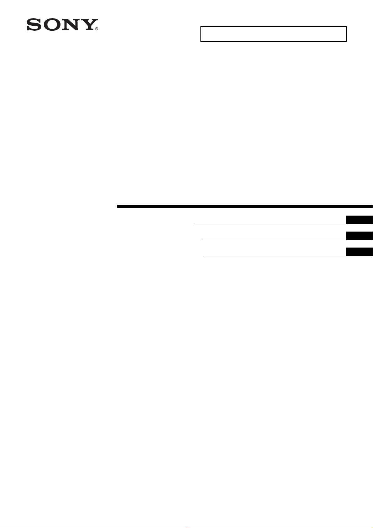
4Connect the AC power cord and
the connecting cable(s) supplied
with the LCD Display to the LCD
Display.
Connect the AC power cord and the connecting
cable(s) to the connectors on the rear of the LCD
Display. For details on connecting the AC power
cord and the connecting cable(s), refer to the
instruction manual of the LCD Display.
• You cannot connect the cables to the LCD Display
after installing it on the Base Bracket.
• Subcontract the cable routing in the wall to a
licensed contractor.
5Detaching the Table-Top Stand
from the LCD Display.
Remove one side of the Table-Top Stand at a
time. Firmly hold the Table-Top Stand
securely with both hands while the other
people lift up the LCD Display.
Repeat the previous step and remove the
other side of the Table-Top Stand.
• Three or more people are required to detach the
Table-Top Stand.
• Be careful not to use excessive force while
detaching the Table-Top Stand from the LCD
Display as it may cause the LCD Display to fall
resulting in personal injury or physical damage to
the LCD Display.
• Take care when handling the Table-Top Stand to
prevent damage to the LCD Display.
• Be careful when lifting the LCD Display as the Table-
Top Stand is detached, the Table-Top Stand may
topple over and cause personal injury.
• Take care when removing the Table-Top Stand from
the LCD Display to prevent it from falling over and
damaging the surface that the LCD Display is sitting
on.
• Do not remove the Table-Top Stand for any reason
other than to install corresponding accessories on
the LCD Display.
• Be sure the LCD Display is vertical before turning
on. To avoid uneven picture uniformity do not
power on the LCD Display with the LCD panel facing
down.
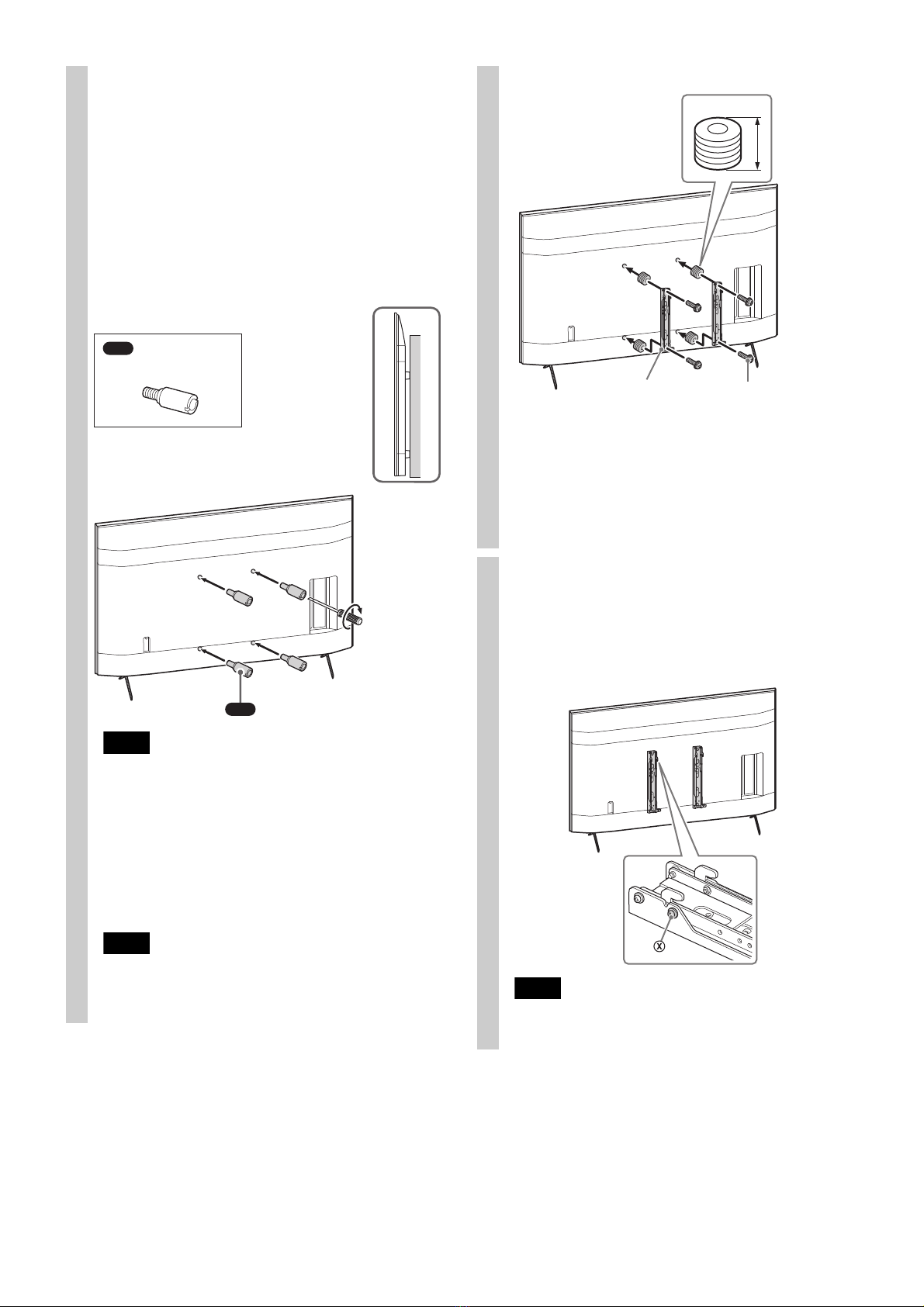
Step 5:
Installing the LCD
Display on the wall
Be sure to complete the installation before
connecting the AC power cord to the wall outlet. If
you allow the AC power cord to be pinched under
or between pieces of equipment, this may result
in a short circuit or an electric shock.
Be careful not to stumble over the AC power cord
or the LCD Display, as you may hurt yourself.