Sony Glasstron PLM-S700E User manual

SERVICE MANUAL
GLASSTRON
AEP Model
SPECIFICATIONS
PLM-S700E
– Continued on next page –
9-928-115-31
Ver 2-1999K
Additional information is
attached at the end of
this manual.

– 2 –
Notes on chip component replacement
• Never reuse a disconnected chip component.
• Notice that the minus side of a tantalum capacitor may be dam-
aged by heat.
Flexible Circuit Board Repairing
• Keep the temperature of the soldering iron around 270 ˚C dur-
ing repairing.
• Do not touch the soldering iron on the same conductor of the
circuit board (within 3 times).
• Be careful not to apply force on the conductor when soldering
or unsoldering.
SAFETY-RELATED COMPONENT WARNING!!
COMPONENTS IDENTIFIED BY MARK !OR DOTTED
LINE WITH MARK !ON THE SCHEMATIC DIAGRAMS
AND IN THE PARTS LIST ARE CRITICAL TO SAFE
OPERATION. REPLACE THESE COMPONENTS WITH
SONY PARTS WHOSE PART NUMBERS APPEAR AS
SHOWN IN THIS MANUAL OR IN SUPPLEMENTS PUB-
LISHED BY SONY.
TABLE OF CONTENTS
1. GENERAL
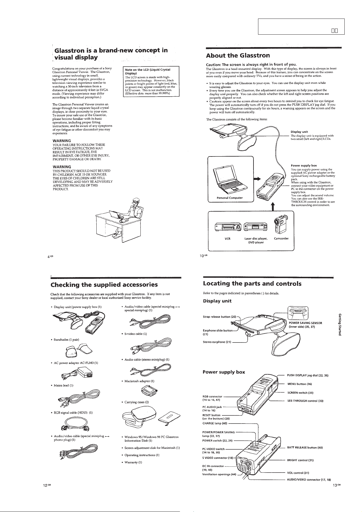
Glasstron is a brand-new concept in visual display .... 1-1
About the Glasstron ..................................................... 1-1
Checking the supplied accessories .............................. 1-1
Locating the parts and controls ................................... 1-1
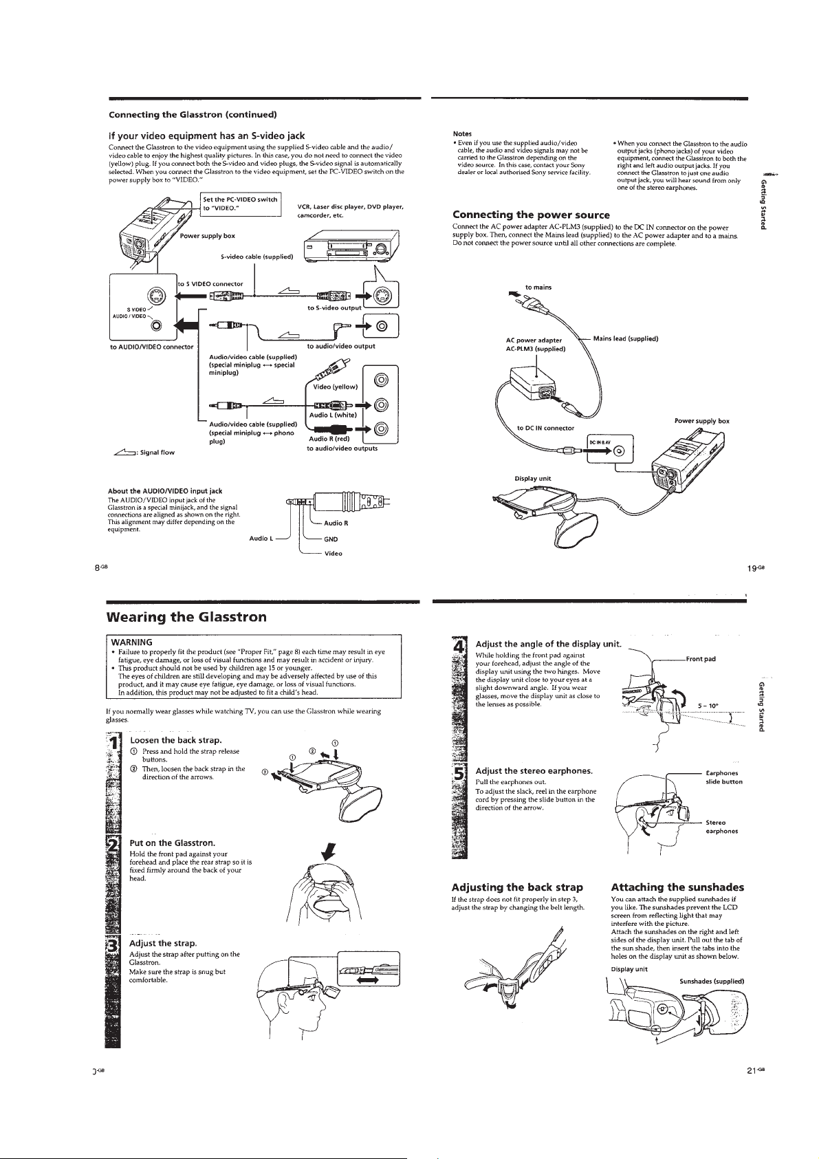
Connecting the Glasstron............................................. 1-2
Wearing the Glasstron.................................................. 1-3
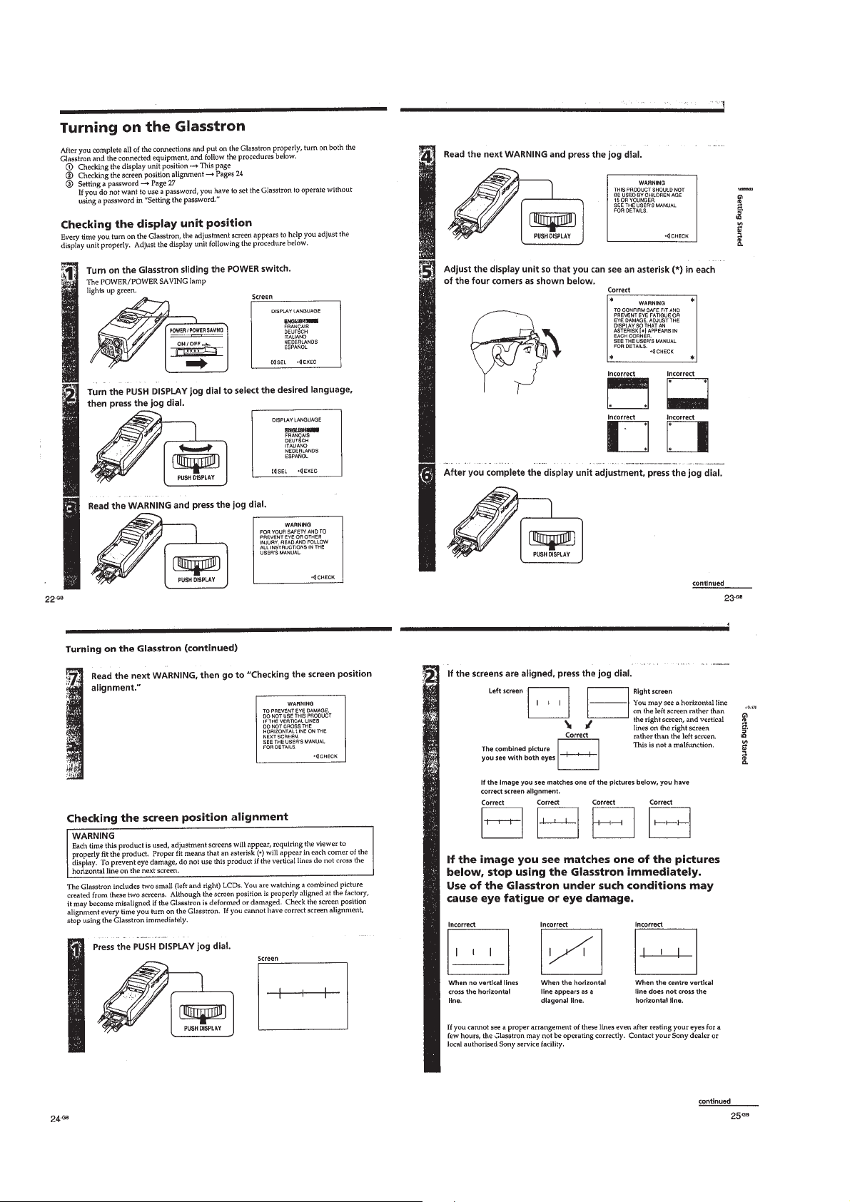
Turning on the Glasstron ............................................. 1-4
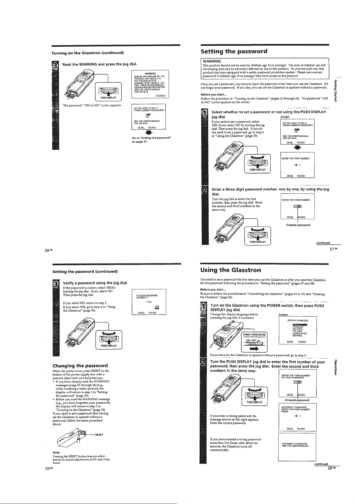
Setting the password .................................................... 1-5
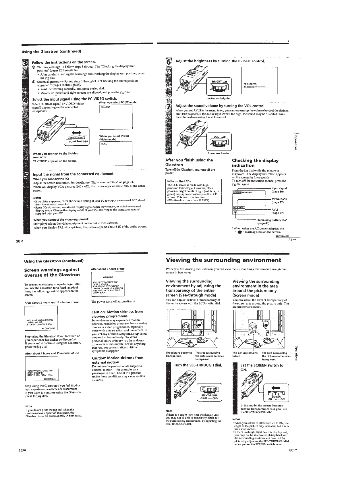
Using the Glasstron...................................................... 1-5
Viewing the surrounding environment ........................ 1-6
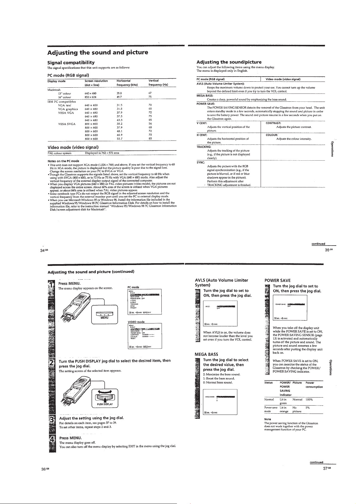
Adjusting the sound and picture .................................. 1-7
Using the optional battery pack................................... 1-8
2. DISASSEMBLY ...................................................... 2-1
3. ELECTRICAL ADJUSTMENTS...................... 3-1
4. DIAGRAMS
4-1. Block Diagram – AUDIO/VIDEO Section – ............. 4-1
4-2. Block Diagram
– A/D, D/A, OSD, SYNC Section – ............................ 4-5
4-3. Block Diagram
– GAMMA CONTROL/LCD DRIVE Section – ........ 4-7
4-4. Block Diagram
– MODE CONTROL/SENSOR/LCS Section – ......... 4-9
4-5. Block Diagram – POWER SUPPLY Section – .......... 4-11
4-6. Notes for Printed Wiring Board and
Schematic Diagram...................................................... 4-14
4-7. Printed Wiring Board – JK-136 Board – .................... 4-15
4-8. Schematic Diagram – JK-136 Board –........................ 4-16
4-9. Schematic Diagram –YC-148 Board (1/3) – .............. 4-17
4-10. Schematic Diagram –YC-148 Board (2/3) – .............. 4-19
4-11. Schematic Diagram –YC-148 Board (3/3) – .............. 4-24
4-12. Printed Wiring Board – YC-148 Board – ................... 4-27
4-13. Printed Wiring Board – MA-324 Board – .................. 4-31
4-14. Schematic Diagram – MA-324 Board (1/7) –............. 4-35
4-15. Schematic Diagram – MA-324 Board (2/7) –............. 4-39
4-16. Schematic Diagram – MA-324 Board (3/7) –............. 4-43
4-17. Schematic Diagram – MA-324 Board (4/7) –............. 4-46
4-18. Schematic Diagram – MA-324 Board (5/7) –............. 4-49
4-19. Schematic Diagram – MA-324 Board (6/7) –............. 4-53
4-20. Schematic Diagram – MA-324 Board (7/7) –............. 4-55
4-21. Printed Wiring Board – LC-61 Board – ..................... 4-57
4-22. Schematic Diagram – LC-61 Board – ......................... 4-59
4-23. Printed Wiring Board – SW-306 Board –................... 4-62
4-24. Schematic Diagram – SW-306 Board – ...................... 4-65
4-25. Printed Wiring Board – DD-107 Board –................... 4-67
4-26. Schematic Diagram – DD-107 Board – ...................... 4-69
4-27. IC Pin Function Description ........................................ 4-88
5. EXPLODED VIEWS............................................. 5-1
6. ELECTRICAL PARTS LIST ............................ 6-1

1-1
SECTION 1
GENERAL This section is extracted from in-
struction manual (3-862-932-
).

1-2

1-3

1-4

1-5

1-6

1-7

1-8
1-8 E

2-1
LOADING BLOCK ASSY
LC-61 BOARD
Note: Follow the disassembly procedure in the numerical order given.
SECTION 2
DISASSEMBLY
1
screw
(M1.4
×
3.0)
3
screw
(M1.4
×
3.0)
1
screw
(M1.4
×
3.0)
1
screw
(M1.4
×
3.0)
1
three screws
(M1.4
×
3.0)
5
rear cabinet assy
2
loading block assy
6
FP661 flexible
board (CN803)
4
two claws
4
two claws
4
two screws
(M1.7
×
5)
5
connection cable
6
LC-61 board
2
connector
(back light unit)
1
front panel
7
flexible board
(CN805)
3
flexible board
(CN802)
3
flexible board
(CN801)
7
flexible board
(CN804)

2-2
BACK LIGHT UNIT
OPTICS BLOCK ASSY, FILM (PANEL) LIQUID CRYSTAL
1
screw
(M1.7
×
5)
3
back light unit
2
claw
1
screw
(P1.7
×
4.0)
3
optics block assy
2
lens fixed plate
4
shutter holder (C)
5
two film (panel) liquid crystals (C)
2-2 E

3-1
5. Setting up Input Signals
(1) Video Signal
In adjusting this set, video signals obtained from the pattern
generator are used, and therefore these video output signals
must satisfy the specification. Connect the oscilloscope to the
VIDEO IN terminal, and confirm that the sync signal ampli-
tude of video signals is approximately 0.3V, the amplitude of
video part is approximately 0.7 V, burst signal amplitude is
approximately 0.3 V and flat, and the level ratio of burst sig-
nal to “red” signal is 0.30 : 0.66.
Where “chroma signal, and color bar signal with burst signal
turned off” is specified in the text, enter chroma signal and
color bar signal of which burst signal is turned off to the VIDEO
IN terminal as video input signals for adjustment.
(2) PC Signal (RGB signal)
SECTION 3
ELECTRICAL ADJUSTMENTS
Precautions on adjustment:
1. Perform the adjustment in the given order.
2. Power supply voltage: DC 8.4 V
3. Equipment required
Electrical adjustment requires the following measuring equip-
ment.
(1) Oscilloscope: 2 phenomena, band 30 MHz or more, with de-
lay mode (use 10 : 1 probe unless otherwise specified)
(2) Pattern generator
(3) Regulated power supply ×2
(4) Digital voltmeter
(5) Frequency counter
(6) Connector for adjustment
4. Measurement points for adjustment are located at CN1003 on
the YC-148 board and at CN206 on the MA-324 board. The
pin No. and signal name of CN1003 and CN206 are listed be-
low.
• YC-148 Board, CN1003
• MA-324 Board, CN206
Preparation:
Connect electrical blocks as shown below.
Pin No. Signal Name
1 GND
2 GND
3 GND
4 4FSC
5 GND
Pin No. Signal Name
6 GND
7 Y OUT
8 VIDEO G
9 N.C
10 GND
Pin No. Signal Name
1 SIG R 1
2A
3 SIG G 1
4 POWER SW
5 SIG B 1
6 ENTER
7 INT H
8 VIDEO/XPC IN
Pin No. Signal Name
9 GND
10 GND
11 B
12 COM R
13 C
14 COM L
15 SIG CEN
16 P SIG B
White (100%)
approx.
0.3 V
approx.
0.7 V
approx.
0.3 V
• When color bar signals are entered
Red
Burst signal (flat)
Horizontal sync signal
Fig. 3-1. Pattern generator's color bar signals
Signal mode H V HDISP VDISP
(kHz) (Hz) (dots) (dots)
PC98 24.82 56.41 640 400
VGA-TEXT 31.47 70.08 640 362
VGA-GRAP 31.47 59.94 640 480
VGA72 37.86 72.82 640 480
VGA75 37.50 74.99 640 480
MAC13’ 35.00 66.67 640 480
VGA85 43.27 85.01 640 480
SVGA56 35.16 56.26 800 600
SVGA60 37.88 60.32 800 600
SVGA72 48.08 72.19 800 600
SVGA75 46.88 75.01 800 600
SVGA85 53.68 85.07 800 600
MAC16’ 49.73 74.55 832 624
XGA60 48.36 59.99 1024 768
VIDEO
SG
AUDIO
SG
Set PC
DC 8.4V suitable
DD-107 board
(J701)
AUDIO/VIDEO terminal
YC-148 board
(J1002)
RGB terminal
MA-324 board
(J101)

3-2
[Preparation for Adjustment]
1. Service Jigs
(1) Adjusting remote commander (RM-95-modified)
Note 1: J-6082-053-B
(2) Extension cable (for remote commander plug converter)
J-6082-291-A
Note 1: The page will not be changed over, unless the microprocessor in
the adjusting remote commander is a new one (UPD7503-G-C56-
12). In such a case, replace with new microprocessor (8-759-
148-35).
2. Adjusting Remote Commander
For the adjustment, the adjustment data saved in the nonvola-
tile memory (EEPROM) must be rewritten, and for this pur-
pose the adjusting remote commander is used.
The adjusting remote commander makes two-way communi-
cation with the product using a remote control signal line
(LANC). The adjusting remote commander transmits pages,
addresses, and data up/down commands to the product. The
product transmits pages, addresses, and data to the adjusting
remote commander.
3. How to Use Adjusting Remote Commander
(1) Connect the adjusting remote commander to the CN501 on
MA-324 board via extension cable (J-6082-291A).
At this time, set the switch of extension cable to OFF
(OPEN) position.
Set the [PC] or [VIDEO] mode and turn ON the power on
the set.
(2) Set the HOLD switch on the adjusting remote commander to
the HOLD (SERVICE) position.
If connection is normal, the LCD display on the adjusting
remote commander will be as shown in Fig.3-2.
Fig. 3-2
(3) Operate the adjusting remote commander as follows:
• Page change
Press the EDIT SEARCH + button to increase the page.
Press the EDIT SEARCH – button to decrease the page.
There are 16 pages from 0 to F.
• Address change
Press the FF ()) button to increase the address.
Press the REW (0) button to decrease the address.
There are 256 addresses from 00 to FF.
• Data change (data setting)
Press the PLAY (() button to increase the data.
Press the STOP (p) button to decrease the data.
There are 256 data from 00 to FF.
• Adjustment data writing
The PAUSE button must be pressed to write adjustment
data (E or F pages) to the nonvolatile memory (EEPROM).
(Unless the PAUSE is pressed, new data are not saved in
the nonvolatile memory.)
(4) Select page: 0, address: FF, and set 01 data. Thus, the data
input to page: E or F is enabled.
(5) After the adjustment finished, select page: 0, address: FF, and
set 00 data. Thus, the data change on page E or F is disabled.
(6) After all adjustments finished, turn OFF the main power sup-
ply (8.4 V) once.
4. Precaution on Use of Adjusting Remote Commander
Misoperation of the adjusting remote commander could erase
correct data.To prevent this, it is recommended to make a note
of data from page E or F before adjustment, and also to make
a note of new adjustment data each time the adjustment of one
item is finished.
Fig. 3-3
Hexadecimal numbers
LCD display
Decimal conversion
0123456789ABCDEF
10 23456789 A b c d E F
10 2 3 4 5 6 7 8 9 10 11 12 13 14 15
Page Data Address
()
HOLD START/
STOP
WIDE
ZOOM
TELE
REC
REVIEW FOCUS
POWER
AUTO/MAN
EDIT SEARCH
COUNTER
RESET DISPLAY FRAME SLOW
REC PAUSE
REW FF
RM-95
STOP
PB
Adjusting Remote Commander RM-95 (J-6082-053-B)
Address
change
NORMAL/SERVICE
mode selection
Page change
Data change
Data writing

3-3
5. Data Processing
Certain adjustment items require the microprocessor data to be read out or the displayed data (hexadecimal numbers) on jigs or
adjusting remote commander to be calculated to get adjustment data. In such a case, convert hexadecimal numbers into decimal
numbers once, then make calculation, and convert its result into hexadecimal number as adjustment data. Table 1 shows hexadecimal
– decimal number conversion.
Hexadecimal – Decimal number conversion.
Table 1.
Note: Data in ( ) are displayed on jig or adjusting remote commander.
Example:If display on jig or adjusting remote commander is BD (bd)
As higher digit of hex. number is B (b) and lower digit is D (d), the intersection “189” of 1and 2in Table 1 is the target decimal number.
1
2
Lower digit
of hex.
Higher digit
of hex.
0123456789A
(A) B
(b) C
(c) D
(d) E
(E) F
(F)
00
1
2
3
4
5
6
7
8
9
A (A)
B (b)
C (c)
D (d)
E (E)
F (F)
123456789
10 11 12 13 14 15
16 17 18 19 20 21 22 23 24 25 26 27 28 29 30 31
32 33 34 35 36 37 38 39 40 41 42 43 44 45 46 47
48 49 50 51 52 53 54 55 56 57 58 59 60 61 62 63
64 65 66 67 68 69 70 71 72 73 74 75 76 77 78 79
80 81 82 83 84 85 86 87 88 89 90 91 92 93 94 95
96 97 98 99 100 101 102 103 104 105 106 107 108 109 110 111
112 113 114 115 116 117 118 119 120 121 122 123 124 125 126 127
128 129 130 131 132 133 134 135 136 137 138 139 140 141 142 143
144 145 146 147 148 149 150 151 152 153 154 155 156 157 158 159
160 161 162 163 164 165 166 167 168 169 170 171 172 173 174 175
176 177 178 179 180 181 182 183 184 185 186 187 188 189 190 191
192 193 194 195 196 197 198 199 200 201 202 203 204 205 206 207
208 209 210 211 212 213 214 215 216 217 218 219 220 221 222 223
224 225 226 227 228 229 230 231 232 233 234 235 236 237 238 239
240 241 242 243 244 245 246 247 248 249 250 251 252 253 254 255

3-4
6. Power ON Procedure for Adjustment
(1) Connect an extension cable to the adjusting remote commander.
(2) Set the [PC] or [VIDEO] mode on the set.
(3) After making sure that the HOLD switch on the adjusting remote commander is not turned on (not at left (NOR) position), supply 8.4
Vdc to the DC IN (J701).
(With the HOLD switch at HOLD position, the initial operation of the set does not finish, disabling the POWER switch function.)
(4) Turn ON the POWER switch on the set. Confirm that a green LED lights up.
(5) Set the HOLD switch on the adjusting remote commander to the HOLD (right (ADJ)) position.
7. Adjustment Finishing Procedure
Order Page Address Data Description Remarks
1. E or F Check if adjusted data are written correctly to the given page and address.
2. 2 FF 00 Set data 00 to given page and address. Page 2: Reset
3. 0 FF 00 Page E or F: Write protect
4. Set HOLD switch on adj. remote commander to NOR position.
8. Password Reset (for operation check of the set)
(1) Turn the POWER switch on, then press the “Password Reset” at the bottom of Power Box to reset the password set by the customer.
(2) Operating the jog dial, select “No” on the Password Set screen to set “disuse of password”.
Or,
Order Page Address Data Description Remarks
1. 0 01 01 Set data 01 to given page and address. Page E or F: Cancel protect
2. E or F 04 FF Set data FF to given page and address and press PAUSE. Set disuse of password
Final: After all adjustments and operation check finished, turn the POWER switch on, press the "Password Reset" at the bottom of Power Box, and
turn the POWER switch off.
9. EXT. VIDEO AUDIO mode: Turn the POWER switch on, and press and operate the jog dial from the initial screen.
Or,
Order Page Address Data Description Remarks
1. 2 00 01 Set data 01 to given page and address.
2. 2 2B 00 Set data 00 to given page and address.
10. Picture and tone quality standard setting: Press the MENU button and set the BRIGHT control.
Or, Set data 01 to page:0, address:01 to cancel the protect on page F.
Order Page Address Data Description Remarks
F 7B 3F Set data 3F to given page and address, and press PAUSE. Ope. – Brightness: Center
F 53 40 Set data 40 to given page and address, and press PAUSE. Ope. – Contrast: Center
F 50 3F Set data 3F to given page and address, and press PAUSE. Ope. – Hue: Center
F 51 3F Set data 3F to given page and address, and press PAUSE. Ope. – Density: Center
F 8C 02 Set data 02 to given page and address, and press PAUSE. Ope.– Bass boost: 0,
VOL. limit: OFF
Volume (Display unit) – Maximum

3-5
[Preset Data Writing]
Connection:
(1) Connect the adjusting remote commander to the CN501 on MA-324 board, and set the [VIDEO] mode (S904).
Data Writing Procedure
(1) Set data: 01 to page: 0, address: 01.
(2) Enter the data given in the table below.
Note: To write the data to the EEPROM, press the PAUSE button on the adjusting remote commander each time the data is set.
(3) After writing all data, set data: 00 to page: 0, address: FF.
E or F Page Adjustment Address and InitialValue
Make setting and adjustment only when IC502 (EEPROM) was replaced.
E Page:
Address Data Remarks
00 01 Fixed value
01 EB
02 DC Charge adj.
03 DA
04 8C
05 DE
06 DC
07 05
08 08
09 07
0A B8 Fixed value
0B 0B
0C 60
0D 54
0E 40
0F – FF – Not used
Address Data Remarks
00 – 0F – Not used
10 00
11 01 Fixed value
12 00
13 FF
14 01 Video adj.
15 03
16 FF
17 00
18 00
19 FF
1A FF
1B FF
1C FF Fixed value
1D FF
1E FF
1F FF
20 00
21 03
22 DE
23 86
24 12
25 1F
26 00
27 00
Address Data Remarks
28 01
29 03
2A 02
2B 05
2C 1D
2D FC
2E 1F
2F 18
30 04
31 40
32 10
33 06
34 47
35 03
36 00
37 00
38 00
39 24
3A 24
3B 24
3C 4C
3D 4C Fixed value
3E 4C
3F 3F
40 3F
41 3F
42 9C
43 9C
44 9C
45 00
46 00
47 00
48 40
49 40
4A 40
4B C1
4C C0
4D C0
4E 41
4F 00
50 40
51 3F
52 7A Video adj.
53 3F Fixed value
Address Data Remarks
54 5B Video adj.
55 80
56 87 H-Sync adj.
57 80 Loading adj.
58 00
59 00
5A 00
5B 00
5C 80
5D 80
5E 80 Fixed value
5F AE
60 AE
61 AE
62 03
63 03
64 03
65 2F
66 2F
67 2F
68 65 R Gain adj.
69 65 G Gain adj.
6A 65 B Gain adj.
6B 94 R Bias adj.
6C 94 G Bias adj.
6D 94 B Bias adj.
6E 80
6F 80
70 80 Fixed value
71 80
72 80
73 80
74 9A SigCen adj.
75 35 V COM R adj.
76 35 V COM L adj.
77 00 Fixed value
78 3E Sid Lvl adj.
79 6A Prg Lvl adj.
7A 60 Blk Lim adj.
7B 1F
7C 00 Fixed value
7D FF
7E 5B Battery down adj.
7F 63
F Page:

3-6
Address Data Remarks
80 73
81 7B Battery down adj.
82 80
83 01
84 49
85 FF
86 00
87 00
88 00
89 00
8A 00
8B 00
8C 02
8D 00 Fixed value
8E 00
8F 00
90 80
91 41
92 00
93 00
94 80
95 41
96 5D
97 29 Video adj.
98 4F
99 FF
9A 80
9B FF
9C 01
9D FF
9E FF
9F FF
A0 81
A1 38
A2 20
A3 3A
A4 1C
A5 40
A6 45
A7 42
A8 45 Fixed value
A9 42
AA A5
AB 44
AC A5
AD 44
AE C0
AF 46
B0 A1
B1 4F
B2 D8
B3 52
B4 11
B5 55
B6 26
B7 58
B8 22
Address Data Remarks
B9 48
BA 5B
BB 4A
BC 17
BD 21
BE A8
BF 22
C0 CB
C1 1A
C2 CF
C3 1B
C4 0C
C5 26
C6 22
C7 28
C8 99
C9 1E
CA EE
CB 1F
CC E1
CD 1C
CE 10
CF 1E
D0 B2
D1 25
D2 BE
D3 27 Fixed value
D4 D9
D5 1D
D6 1E
D7 1F
D8 1D
D9 2D
DA 14
DB 30
DC 68
DD 1A
DE 68
DF 1A
E0 B4
E1 28
E2 19
E3 2B
E4 1D
E5 2D
E6 14
E7 30
E8 AD
E9 25
EA B8
EB 27
EC AD
ED 1D
EE EE
EF 1E
F0 84
F1 28
Address Data Remarks
F2 E3
F3 2A
F4 B6
F5 38
F6 78
F7 3D
F8 CC Fixed value
F9 1A
FA 03
FB 00
FC 00
FD 00
FE 00 Charge adj.
FF FF Fixed value

3-7
VIDEO BLOCK
To adjust the video block, connect a pattern generator as shown
below. As video input signals for adjustment, enter video output
signals (color bar signals), unless otherwise specified.
Preparation: Page Address Data
Sub-Color PAL F 54 5B
(NTSC) (F) (54) (80)
Switch the PAL F 14 01
Signal mode (NTSC) (F) (14) (00)
[4fsc FreeRun Adjustment]
Condition:
Input signal No signal
Measurement point YC-148 board CN1003 pin 4
Measuring equipment Frequency Counter
Adjustment page F
Adjustment address 55
Specification value 17.73450 MHz ± 20 Hz (PAL)
Connection:
Adjustment Procedure:
(1) Connect a frequency counter to the CN1003 pin 4on the
YC-148 board.
(2) Set (or confirm) data: 01 to page: 0, address: 01.
(Cancel F page protect)
(3) On page: F, address: 55, change data with the PLAY and
STOP buttons and press the PAUSE button to write data so
that the frequency counter reading satisfies the specification
value.
Adjustment andAdjustment Parts:YC-148 board (see page 3-15)
[Video Mute Level Adjustment]
Condition:
Input signal All black (IRE 0%) signal (No set up)
Measurement point YC-148 board CN1003 pin 7
Measuring equipment Oscilloscope
Adjustment page F
Adjustment address 52
Specification value 0 ± 0.03 Vp-p
Connection:
Adjustment Procedure:
(1) Connect a oscilloscope to the CN1003 pin 7on theYC-148
board.
(2) Set (or confirm) data: 01 to page 0, address 01. (Cancel F
page protect)
(3) On page F, address: 52, change data with the PLAY and STOP
buttons and press the PAUSE button to write data so that the
Alevel of wafeform on the oscilloscope satisfies the speci-
fication value.
Adjustment andAdjustment Parts:YC-148 board (see page 3-15)
VIDEO IN jack (J1002)
Pattern Generator
Set
CN1003 pin
4\
(4FSC)
YC-148 Board Frequency Counte
r
+
–
+
–
Oscilloscope
(DC range)
CN1003 pin
7
(YOUT)
CN1003 pin
1
(GND)
YC-148 Board
9H 10H 25H
24H11H
A

3-8
[Video Contrast Adjustment]
Condition:
Input signal 10 step signal (Whie: 100 IRE level)
Measurement point YC-148 board CN1003 pin 8
Measuring equipment Oscilloscope
Adjustment page F
Adjustment address 96
Specification value 0.7 ± 0.02 Vp-p
Connection:
Adjustment Procedure:
(1) Connect a oscilloscope to the CN1003 pin 8on theYC-148
board.
(2) Set (or confirm) data: 01 to page 0, address 01. (Cancel F
page protect)
(3) On page F, address: 96, change data with the PLAY and STOP
buttons and press the PAUSE button to write data so that the
Blevel of wafeform on the oscilloscope satisfies the speci-
fication value.
Adjustment andAdjustment Parts:YC-148 board (see page 3-15)
[Color Adjustment]
Condition:
Input signal Color bar signal
Measurement point YC-148 board CN1003 pin 8
Measuring equipment Oscilloscope
Adjustment page F
Adjustment address 98
Specification value 0 ± 0.02 Vp-p
Connection:
Adjustment Procedure:
(1) Connect a oscilloscope to the CN1003 pin 8on theYC-148
board.
(2) Set (or confirm) data: 01 to page 0, address 01. (Cancel F
page protect)
(3) On page F, address: 98, change data with the PLAY and STOP
buttons and press the PAUSE button to write data so that the
Clevel of wafeform on the oscilloscope satisfies the speci-
fication value.
Adjustment andAdjustment Parts:YC-148 board (see page 3-15)
[Hue Adjustment]
Condition:
Input signal Color bar signal
Measurement point YC-148 board CN1003 pin 8
Measuring equipment Oscilloscope
Adjustment page F
Adjustment address 97
Specification value 0 ± 0.02 Vp-p
Connection:
Adjustment Procedure:
(1) Connect a oscilloscope to the CN1003 pin 8on theYC-148
board.
(2) Set (or confirm) data: 01 to page 0, address 01. (Cancel F
page protect)
(3) On page F, address: 97, change data with the PLAY and STOP
buttons and press the PAUSE button to write data so that the
Dlevel of wafeform on the oscilloscope satisfies the speci-
fication value.
Adjustment andAdjustment Parts:YC-148 board (see page 3-15)
+
–
Oscilloscope
(DC range)
CN1003 pin
8
(VIDEO G)
CN1003 pin
1
(GND)
YC-148 Board
B
+
–
Oscilloscope
(DC range)
CN1003 pin
8
(VIDEO G)
CN1003 pin
1
(GND)
YC-148 Board
C
+
–
Oscilloscope
(DC range)
CN1003 pin
8
(VIDEO G)
CN1003 pin
1
(GND)
YC-148 Board
D
Other manuals for Glasstron PLM-S700E
1
Table of contents
Other Sony Virtual Reality Headset manuals

Sony
Sony PlayStation VR CUH-ZVR2 User manual

Sony
Sony PLAYSTATION VR User manual

Sony
Sony PlayStation VR CUH-ZVR2 User manual

Sony
Sony PLM-A35 - Glasstron - 0.55" LCD Passive Matrix Head Mounted... User manual

Sony
Sony PLAYSTATION VR User manual

Sony
Sony Glasstron PLM-A35E User manual

Sony
Sony VR-2 User manual