Sorel Pool TDCM+ User manual

Read carefully before installation, commissioning and operation
Pool Controller
Pool TDCM+
Installation and operating instructions

Table of Contents
Safety instructions
A.1. EC declaration of conformity 3
A.2. General instructions 3
A.3. Explanation of symbols 3
A.4. Changes to the unit 4
A.5. Warranty and liability 4
Description of controller
B.1. Specications 5
B.2. Temperature resistance table for PT1000
sensors 5
B.3. About the controller 6
B.4. Scope of supply 6
B.5. Disposal and pollutants 6
B.6. Hydraulic variants 7
Installation
C.1. Wall installation 8
C.2. Electrical connection 9
C.3. Installing the temperature sensors 10
D. Terminal connection diagram 11
Operation
E.1. Display and input 12
E.2. Commissioning help 13
E.3. Free commissioning 13
E.4. Menu sequence and menu structure 14
1. Measurement values 15
2. Statistics 16
2.1. Operating hours 16
2.2. Average pool temperature 16
2.3. Heat output 16
2.4. Graphic overview 16
2.5. Message log 16
2.6. Reset/clear 16
3. Display mode 17
3.1. Schematic 17
3.2. Overview 17
3.3. Alternating 17
3.4. Sleep mode 17
4. Operating mode 18
4.1. Automatic 18
4.2. Manual 18
4.3. O 18
5. Settings 19
5.1. Tmin S1 19
5.2. Tmax S2 19
5.3. ∆TR1 20
5.4. TsetS2 20
5.5.Hysteresis 20
5.6. Followup/Switch-odelay 20
pagepage
5.7. Delay/Switch-ondelay 20
Filterpumpruntime 20
5.8. Hourlylterpumpruntime 20
5.9. Eco mode 21
5.10. Runtimeoptimization 21
5.11. Dailylteringtime 21
5.12. Solar times 21
5.13. Heating times 21
6. Protective functions 21
6.1. Seizingprotection 21
6.2. Frost protection 21
6.3. System protection 22
7. Special functions 23
7.1. Program selection 23
7.2. Time and date 23
7.3. Sensor calibration 23
7.4. Commissioning 24
7.5. Factory settings 24
7.6. Heat quantity 24
7.7. Daylight saving time 25
8. Menu lock 26
9. Service values 27
10. Language 28
Malfunctions
Z.1. Malfunctions with error messages 29
Z.2. Replacing the fuse 30
Z.3. Maintenance 30
3
Safety instructions
ByaxingtheCEmarktotheunitthemanufacturerdeclaresthatthePool TDCM+ con-
formstothefollowingrelevantsafetyregulations:
- EClowvoltagedirective2006/95/EC
- ECelectromagneticcompatibilitydirective2004/108/EC
ConformityhasbeenveriedandthecorrespondingdocumentationandtheECdeclaration
ofconformityarekeptonlebythemanufacturer.
A.1. EC declaration of conformity
These installation and operating instructions contain basic instructions and important
informationregardingsafety,installation,commissioning,maintenanceandtheoptimal
useoftheunit.Thereforetheseinstructionsmustbereadcompletelyandunderstood
bytheinstallationtechnician/specialistandbythesystemuserbeforeinstallation,com-
missioningandoperationoftheunit.
Thevalidaccidentpreventionregulations,VDEregulations,theregulationsofthelo-
calpowerutility,theapplicableDIN-ENstandardsandtheinstallationandoperating
instructionsoftheadditionalsystemcomponentsmustalsobeobserved.Thecon-
trollerdoesnotunderanycircumstancesreplaceanysafetydeviceswhicharetobe
provided by the customer!
Installation,electricalconnection,commissioningandmaintenanceoftheunitmay
only be carried out by specialists who have the appropriate training.
Fortheuser:Makesurethatthespecialistgivesyoudetailedinformationonthefunc-
tionandoperationofthecontroller.Alwayskeeptheseinstructionsinthevicinityofthe
controller.
A.2. General instructions
Danger
Caution
A.3. Explanation of symbols
Failuretoobservetheseinstructionscanresultindangertolifefrom
electric voltage.
Danger
Failure to observe these instructions can result in serious damage to
healthsuchasscalding,orevenlife-threateninginjuries.
Caution
Failuretoobservetheseinstructionscanresultindestructionoftheunit
orthesystem,ordamagetotheenvironment.
Informationwhichisespeciallyimportantforthefunctionandoptimaluse
oftheunitandthesystem.

4
A.4. Changes to the unit
A.5. Warranty and liability
Safety instructions
• Changes,additionstoorconversionoftheunitarenotpermittedwithoutwritten
authorisationfromthemanufacturer
• Itislikewiseforbiddentoinstalladditionalcomponentsthathavenotbeentested
together with the unit
• Ifitbecomesclearthatsafeoperationoftheunitisnolongerpossible,forexample
becauseofdamagetothehousing,turnthecontrolleroimmediately
• Anypartsoftheunitoraccessoriesthatarenotinperfectconditionmustbere-
placed immediately
• Useonlyoriginalsparepartsandaccessoriesfromthemanufacturer
• Markingsmadeontheunitatthefactorymustnotbealtered,removedormade
illegible
• Only the settings described in these instructions may be used on the control-
ler
Changestotheunitcancompromisethesafetyandfunctionoftheunitor
the entire system.
Danger
Thecontrollerhasbeenmanufacturedandtestedwithregardtohighqualityandsafety
requirements.Theunitissubjecttothestatutoryguaranteeperiodoftwoyearsfrom
thedateofsale.
Thewarrantyandliabilityshallnotinclude,however,anyinjurytopersonsormaterial
damagethatisattributabletooneormoreofthefollowingcauses:
• Failure to observe these installation and operating instructions
• Improperinstallation,commissioning,maintenanceandoperation
• Improperrepairs
• Unauthorised structural changes to the unit
• Installationofadditionalcomponentsthathavenotbeentestedtogetherwith
the unit
• Anydamageresultingfromcontinueduseoftheunitdespiteanobviousfault
• Failure to use original spare parts and accessories
• Useofthedeviceforanythingotherthanitsintendedpurpose
• Operationaboveorbelowthelimitvalueslistedinthespecications
• Forcemajeure

5
B.2. Temperature resistance table for PT1000 sensors
B.1.
°C 0 10 20 30 40 50 60 70 80 90 100
Ω1000 1039 1077 1116 1155 1194 1232 1270 1308 1347 1385
Description of controller
Electrical
mechanical relay 4 A maximum AC3
920VA for AC1 (non-inductive loads) / 460 VA for AC3 (for inductive loads such as electric motors for
filter pumps)
PT1000 sensor input measuring range -40 °C to 300 °C
2 (R1-R2)
3
Permissible cable length of sensors and appliances:
Collector and outdoor sensor < 30 m
Other PT1000 sensors < 10 m
Electronic relay < 3 m
Mechanichal relay < 10 m
Real Time Clock RTC with 24 hour power reserve
Permissible ambient conditions:
Ambient temperature
for controller operation 0 °C ... 40 °C
for transport/storage 0 °C ... 60 °C
Air humidity
for controller operation max. 85 % rel. humidity at 25 °C
for transport/storage no moisture condensation permitted
Other and dimensions
Housing design 3-part, ABS plastic
Installation methods Wall installation, optional panel
Overall dimensions 163 mm x 110 mm x 52 mm
Cut out installation dimensions 157 mm x 106 mm x 31 mm
Display Fully graphical display, 128 x 128 dots
Light diode Multicolor red / green
Operation 4 entry keys
Mains voltage 230 VAC +/-10 %
Mains frequency 50 - 60 Hz
Power consumption 1.5 W - 2.3 W
Internal fuse 4 A slow blow 250 V
Protection category IP40 / IP 44 (only with the supplied
seal kit)Protection class II
Overvoltage Category II
Degree of Pollution Category II

6
The Pool Controller Pool TDCM+facilitatesecientuseandfunctioncontrolofyour
solarorheatingsystemwithyourswimmingpool.Thedeviceisimpressivemostof
allforitsfunctionalityandsimple,almostself-explanatoryoperation.Foreachstepin
theinputprocesstheindividualentrykeysareassignedtoappropriatefunctionsand
explained.Thecontrollermenucontainsheadwordsforthemeasuredvaluesandset-
tings,aswellashelptextsorclearly-structuredgraphics.
The BADU®Logic 1canbeusedasasolarcontrollerforthevarioussystemvariants
illustrated and explained under “B.6. Hydraulic variants” on page 7.
ImportantcharacteristicsofthePool TDCM+:
- Depictionofgraphicsandtextsinanilluminateddisplay
- Simpleviewingofthecurrentmeasurementvalues
- Analysisandmonitoringofthesystembymeansofstatisticalgraphics,etc.
- Individualcongurationofspecialfunctions
- Extensive menu settings with explanations
- Menublockactivationtopreventunintentionalsettingchanges
- Resettingtopreviouslyselectedvaluesorfactorysettings
- Awiderangeofadditionalfunctions
B.3. About the controller
Description of controller
- Pool Controller Pool TDCM+
- 3pcs.3.5x35mmscrewsand3pcs.6mmplugsforwallinstallation
- 6strainreliefclipswith12screws,replacementfuse1xT4A/250V
- InstallationandoperatinginstructionsPool TDCM+
Optionallycontaineddependingondesign/order:
- PT1000temperaturesensorsandimmersionsleeves
Additionallyavailable:
- PT1000temperaturesensor,immersionsleeves,overvoltageprotection
B.4. Scope of supply
B.5. Disposal and pollutants
TheunitconformstotheEuropeanRoHSdirective2011/65/EUfortherestrictionofthe
useofcertainhazardoussubstancesinelectronicequipment.
Caution
Theunitmustnotunderanycircumstancesbedisposedofwithordinary
householdrefuse.Disposeoftheunitonlyatappropriatecollectionpoints.

7
B.6. Hydraulic variants
Description of controller
Caution
Thefollowingillustrationsshouldbeviewedonlyasschematicdia-
grams showing the respective hydraulic systems and do not claim to
becomplete.Thecontrollerdoesnotreplacesafetydevicesunderany
circumstances.Dependingonthespecicapplication,additionalsystem
componentsandsafetycomponentsmayberequired,suchascheck
valves,non-returnvalves,safetytemperaturelimiters,scaldingprotec-
torsetc.andmustthereforebeprovided.
Poolwithsolar,ballvalveandlterpumpcontrol
Poolwithauxiliaryheater,ballvalveandlter
pump control
Poolwithheatpump,ballvalveandlterpump
control
Poolwithheatpump,heatexchangerandlter
pump control
Poolwithlterpumpcontrol
Poolwithsolar,ballvalve,auxiliarypumpand
lterpumpcontrol
8
C.1.1 .
C.1.2.
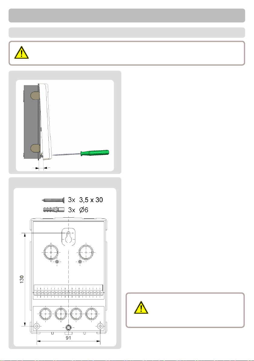
Caution
C.1. Wall installation
Installthecontrollerindryareasonlyandundertheambientconditionsde-
scribedunder“B.1.Specications”.
1. Unscrew cover completely
2.Carefullypullupperpartofhousing
fromlowerpart.Terminalclampsare
released during this process.
3.Setupperpartofhousingaside,being
sure not to touch the electrics when doing
so.
4.Holdthelowerpartofthehousingup
totheselectedpositionandmarkthe3
mountingholes.Makesurethatthewall
surfaceisasevenaspossiblesothatthe
housing does not become distorted when
it is screwed on.
5.Usingadrillandsize6bit,drill3holes
atthepointsmarkedonthewallandpush
in the plugs.
6.Inserttheupperscrewandscrewitin
slightly.
7.Fittheupperpartofthehousingand
insert the other two screws.
8. Align the housing and tighten the three
screws.
Installation
Controller must be inaccessible
fromtherear.
Caution
9
Installation
C.2. Electrical connection
Danger
Beforeworkingontheunit,switchothepowersupplyandsecureitfrom
beingswitchedonagain!Checkfortheabsenceofpower!
Electrical connections may only be made by a specialist and in compli-
ance with the applicable regulations.
Donotusethecontrollerifthehousingshowsvisibledamage.
Caution
Low-voltage cables such as temperature sensor cables must be routed
separatelyfromthemainsvoltagecables.Feedtemperaturesensorca-
blesonlyintotheleft-handsideoftheunit,andmainsvoltagecablesonly
into the right-hand side.
Caution
Thecustomermustprovideanall-poledisconnectingdevice,
e.g. a heating emergency switch.
Caution
The cables being connected to the unit must not be stripped by more than
55mm,andthecablejacketmustreachintothehousingjusttotheother
sideofthestrainrelief.
Achtung
FollowtheprotectiveareastoGermanInstituteforStandardizationVDE0100-702for
theinstallationofthecontrol(distancestoSchuztbereich0and1).
Achtung
Electricshockdangerbyimproperconnection!
• VDE-andEVUregulationsoftheenergysupplyenterprisefollow.
• Pumps and swimming pools and their protective area according to
GermanInstituteforStandardizationVDE0100-702instal.
• Dividingdevicefortheinterruptionofthetensioncarewithmin3
mmofcontactopeningperpoolinstal.
Electricshockdangerbytensioninthecase!
• A correctly opposed engine guard counter must be installed. Be-
sides,thevaluesonthetypesignfollow.
• Circuitwithamistakestreamprotectioncounter,nominalmistake
streamI∆N≤30mA.
• Onlysuitablemanagementtypesaccordinglyoftheregionalregula-
tions use.
• Leastcrosssectionofthelines,theenginepowerandtheachieve-
ment situation adapt.
• Ifdangeroussituationscanarise,emergency-fromcounteraccord-
ingtoGermanInstituteforStandardizationEN809plan.According
to this norm the Errichter/operator must decide this.

10
1. Select necessary program/hydraulics.
2. Opencontrollercasing(“C.1.Wall
installation”onpage8).
3. Stripcablesby55mmmax.,insert,t
thestrainreliefdevices,stripthelast
8-9mmofthewires.
4. Open the terminals using a suitable
screwdriver(Fig.C.2.1.)andmake
electrical connections on the control-
ler.
5. Retterminalconnectioncoverand
fastenscrew.
6. Switch on mains voltage and place
controller in operation.
C.2.2.
Installation
C.3. Installing the temperature sensors
Thetemperaturesensorcablesmustberoutedseparatelyfrommainsvoltage
cablesandmustnot,forexample,beroutedinthesamecableduct!
ThecontrolleroperateswithPT1000temperaturesensorswhichareaccuratetothe
degree,thusensuringoptimalcontrolofsystemfunctions.
Ifdesiredthesensorcablescanbeextendedtoamaximumof30musing
acablewithacross-sectionofatleast0.75mm².Makesurethatthereisno
contact resistance!
Position the sensor precisely in the area to be measured!
Onlyuseimmersion,pipe-mountedorat-mountedsensorssuitableforthe
specicareaofapplicationwiththeappropriatepermissibletemperaturerange.
Caution
Caution
11
Installation
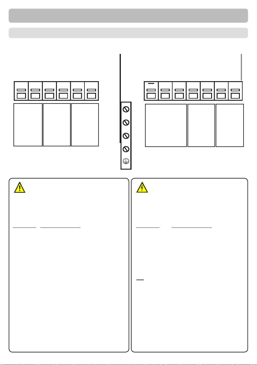
Low voltagemax.12VAC/DC
Terminal Connectionfor
S1(2x) Collector
S2(2x) Pool
S3(2x) Flowsensor(optional)
Mains voltage230VAC50-60Hz
Terminal Connectionfor
N MainsneutralconductorN
R1 Filter pump
N MainsneutralconductorN
L Mains phase conductor L
N MainsneutralconductorN
R2 Ballvalve,heatpump
or auxiliary pump
R2 Ball valve
The PE protective conductor must be
connected to the PE metal terminal
block!
max.12V
Caution
Mainsvoltages230VAC
Danger
D. Terminal connection diagram
Low voltage Relays Mains
MainsRelaisKleinspannungen
S3
S3 S2 S2 S1 S1 R2 R1LN N NR2
Flow sensor
Ballvalve,
heat pump
or auxiliary
pump
Pool
Supply
Collector
Filter pump
12
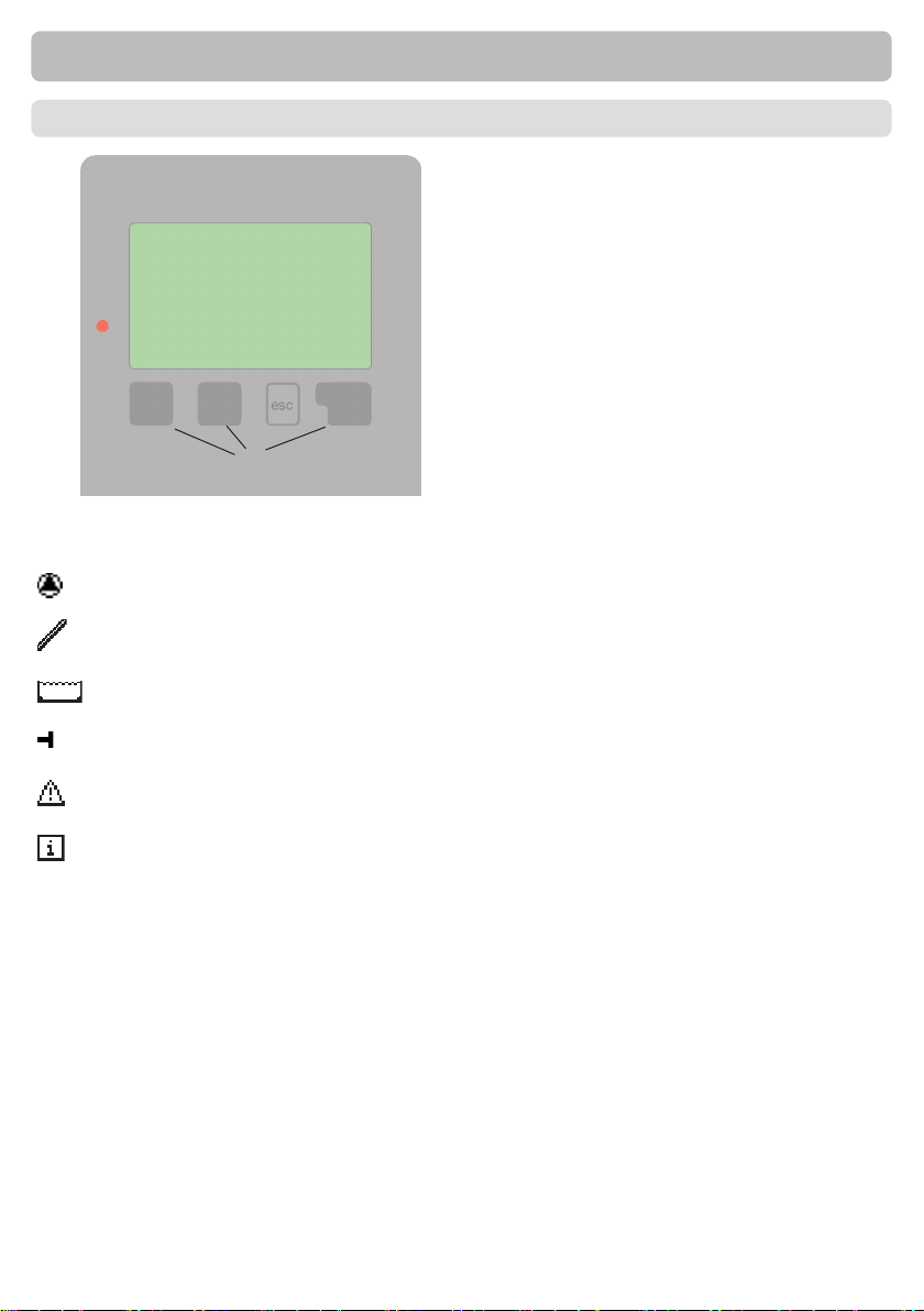
Examplesofdisplaysymbols:
Pump(rotatesinoperation)
Collector
Pool
Temperature sensor
Warning / Error message
Newinfos
(1)
(2)
(3)
(4)
Thedisplay(1),withitsextensivetextand
graphicsmode,isalmostself-explanatory,
allowingeasyoperationofthecontroller.
Tochangefromtheoverviewtotheset-
tingsmenu,pressthe„esc“key.
ThegreenstatusLED(2)lightsupwhena
solarrequirementistaktiv(Ballvalueon/
o)OtherfeaturesoftheLEDaredis-
cribed in nChapter Z.1.
Inputsaremadewith4buttons(3+4),
whichhavedierentfunctionsdepending
on the context.
The„esc“key(3)isalwaysusedtocancel
or exit a menu.
Ifapplicabletherewillbearequestfor
conrmationastowhetherthechanges
which have been made should be saved.
Thefunctionofeachoftheotherthree
keys(4)isshowninthedisplaylinedi-
rectlyabovethekeys;theright-handkey
generallyhasaconrmationandselection
function.
Examplesofkeyfunctions:
+/- =enlarge/shrinkvalues
▼/▲ =scrolldown/upmenu
yes/no = approve/cancel
Info =additionalinformation
Back =topreviousscreen
ok =conrmselection
Conrm =conrmsetting
Operation
E.1. Display and input

13
E.2. Commissioning help
E.3. Free commissioning
Ifyoudecidenottousethecommissioninghelp,youshouldmakethenecessaryset-
tingsinthefollowingsequence:
-Menu 10. Language
- Menu 7.2. Time and date
- Menu 7.1. Program selection
-Menu 5. Settings,allvalues
-Menu 6. Protectivefunctions,ifnecessary
-Menu 7. Specialfunctions,ifnecessary
Finally,themenu“4.2.Manual”onpage18shouldbeusedtotesttheswitchout-
putswiththeconsumersconnectedandtocheckthesensorvaluesforplausibility.
Then the automatic mode can be switched on.
Commission
Caution
Observetheexplanationsfortheindividualparametersonthefollowing
pagesandcheckwhetherfurthersettingsarenecessaryforyour
application.
display.Pressingthe“esc”keytakesyoubacktothepreviousvaluesoyoucanlookat
theselectedsettingagainoradjustitifdesired.Pressingthe“esc“keymorethanonce
takesyoubackstepbysteptotheselectionmode,thuscancellingthecommissioning
help.Finally,themenu“4.2.Manual”onpage18shouldbeusedtotesttheswitch
outputswiththeconsumersconnectedandtocheckthesensorvaluesforplausibility.
Then the automatic mode can be switched on.
Thersttimethecontrolleristurnedonand
afterthelanguageandtimeareset,aquery
appears as to whether you want to para-
metrise the controller using the commissioning
help or not. The commissioning help can also
be terminated or called up again at any time in
thespecialfunctionsmenu.Thecommission-
ing help guides you through the necessary ba-
sicsettingsinthecorrectorder,andprovides
briefdescriptionsofeachparameterinthe
Caution
Observetheexplanationsforthetheindividualparametersonthefol-
lowingpagesandcheckwhetherfurthersettingsarenecessaryforyour
application.

14
E.4. Menu sequence and menu structure
Operation
The graphics or overview mode appears
whennokeyhasbeenpressfor2minutes
or when the main menu is exited by press-
ing “esc“.
The up and down buttons are used to
scrollthroughthelistofsensorsand
relays.
Youcanenterthemainmenubypressing
the“esc“key.Thefollowingmenusare
available:
Current temperature values with explana-
tions
Functioncontrolofthesystemwithoperat-
ing hours etc.
Automaticmode,manualmodeorswitch
unito
Setparametersneededfornormalopera-
tion
Frostprotection,anti-seizingprotection
etc.
Programselection,sensorcalibration,
clock,additionalsensoretc.
Against unintentional setting changes at
critical points
Fordiagnosisintheeventofanerror
Language selection
Select graphics mode or overview mode
1. Measurement values
2. Statistics
3. Display mode
4. Operating mode
5. Settings
6.Protectivefunctions
7.Specialfunctions
8.Menulock
9. Service values
10.Language

15
Caution
The measurement values are explained
with a help text when selected.
Selecting “Overview” or “esc” exits the
Infomode.
If“--”appearsonthedisplayinsteadofthemeasurementvalue,then
theremaybeafaultyorincorrecttemperaturesensor.Ifthecablesare
toolongorthesensorsarenotplacedoptimally,theresultmaybesmall
deviationsinthemeasurementvalues.Inthiscasethedisplayvalues
canbecompensatedforbymakingentriesonthecontroller.Followthe
instructions under “7.3. Sensor calibration” on page 23.
What measurement values are displayed depends on the selected pro-
gram,theconnectedsensorsandthespecicdevicedesign.
Measurement values
1. Measurement values
The menu “1. Measurement values” serves
to display the currently measured tempera-
tures.
The menu is closed by pressing the “esc”
keyorselecting“Exitmeasurementvalues”.
16
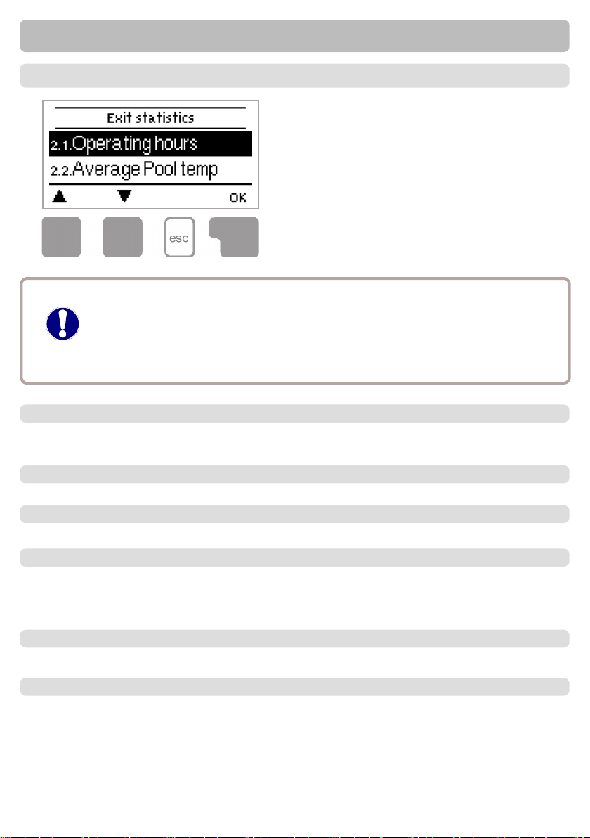
2. Statistics
Achtung
Themenu“2.Statistics”isusedforfunc-
tioncontrolandlong-termmonitoringof
the system.
The menu is closed by pressing the “esc”
keyorselecting“Exitstatistics”.
Foranalysisofthesystemdataitisessentialforthetimetobesetac-
curatelyonthecontroller.Pleasenotethattheclockonlyhasabattery
reservefor24hoursandmustthereforeberesetafterwards.Improper
operationoranincorrecttimemayresultindatabeingdeleted,recorded
incorrectly or overwritten.
Themanufactureracceptsnoliabilityfortherecordeddata!
Statistics
2.1. Operating hours
Displayofoperatinghoursofthepumpconnectedtothecontroller;varioustime
ranges(day-year)areavailable.
Displays the average pool temperature.
2.2. Average pool temperature
2.3. Heat output
Displays the system’s heat output. See also “7.6. Heat quantity” on page 25
2.4. Graphic overview
Thisprovidesaclearlyorganiseddisplayofthedatalistedunder2.1....2.2.asabar
graph.Varioustimerangesareavailableforcomparison.Thetwoleft-handkeyscanbe
used to page through the data.
2.5. Message log
Displaysthelast20eventsoccurringinthesystemwithindicationofdateandtime.
Resettinganddeletingtheindividualanalyses.Thefunction“Allstatistics”clearsall
analyses but not the error messages.
2.6. Reset/clear

17
The menu “3. Display mode” is used to
denethecontroller’sdisplayfornormal
operation.
This display appears whenever two min-
utesgobywithoutanykeybeingpressed.
The main menu appears again when a
keyispressed.
The menu is closed by pressing the “esc”
keyorselecting“Exitdisplaymode”.
Display mode
3. Display mode
3.1. Schematic
Ingraphicsmode,theselectedhydraulicsystemsaredepictedwiththemeasured
temperaturesandoperatingstatesoftheconnectedconsumers.
3.2. Overview
Inoverviewmode,themeasuredtemperaturesandoperatingstatesoftheconnected
consumersaredepictedintextform.
3.3. Alternating
Inalternatingmodetheschematicmodeandthentheoverviewmodeareactivefor5
seconds at a time.
Whenactive,thedisplay’sbacklightisswitchedoafter2minutesofinactivity.
3.4. Sleep mode
Caution
Ifamessageiswaiting,thebacklightisnotswitchedo.
18
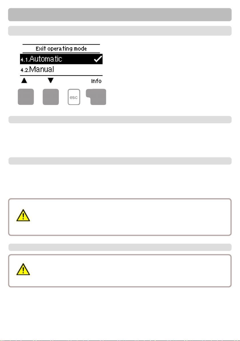
4. Operating mode
Inthemenu“4.Operatingmode”thecon-
troller can either be placed in automatic
mode,switchedoorplacedinamanual
operating mode.
The menu is closed by pressing the “esc”
keyorselecting“Exitoperatingmode”.
Operating mode
Automaticmodeisthenormaloperatingmodeofthecontroller.Onlyautomaticmode
providespropercontrollerfunctiontakingintoaccountthecurrenttemperaturesand
theparametersthathavebeenset!Afteraninterruptionofthemainsvoltagethecon-
troller automatically returns to the last operating mode selected!
4.1. Automatic
4.2. Manual
Therelayandthustheconnectedconsumerareswitchedonando,withnoregard
tothecurrenttemperaturesandtheparameterswhichhavebeenset,bypressinga
key.Themeasuredtemperaturesarealsoshowntoprovideanoverviewandfunction
control.
Danger
Whenoperatingmode“Manual”isactivated,thecurrenttemperaturesand
theselectedparametersarenolongerconsidered.Thereisadangerof
scalding or serious damage to the system. The operating mode “Manual”
mayonlybeusedbyspecialistsforbrieffunctiontestsorduringcommis-
sioning!
4.3. O
Whentheoperatingmode“O”isactivated,allcontrollerfunctionsare
switchedo.Thiscanlead,forexample,tooverheatingonthesolarcol-
lector or other system components. The measured temperatures are still
displayed to provide an overview.
Caution

19
5. Settings
Settings
Thenecessarybasicsettingsrequiredforthe
controlfunctionaremadeinmenu“5.Set-
tings”.
Caution
This does not under any cir-
cumstancesreplacethesafety
facilitiestobeprovidedbythe
customer!
Themenuisclosedbypressingthe“esc”key
or selecting “Exit settings”.
Thefollowingpagescontaingenerallyvaliddescriptionsforthesettings.
Enumerations may vary.
Caution
5.1. Tmin S1
Enable/start temperature at sensor 1
Ifthisvalueisexceededatsensor1andtheotherconditionsarealsomet,thenthe
controllerswitchestheassociatedpumpand/orballvalueon.Ifthetemperatureat
sensor1dropsbelowthisvalueby5°C,thepumpand/orthevalveareswitchedo
again. Setting range: 0 °C ... 99 °C / Default: 20 °C
5.2. Tmax S2
Switch-otemperatureatsensor2
Ifthisvalueisexceededatsensor2,thecontrollerswitchestheassociatedpumpand/
orvalveo.Ifsensor2fallsbelowthisvalueagainandtheotherconditionsarealso
met,thecontrollerswitchesthepumpand/orballvalueonagain.
Setting range: 0 °C ... 99 °C / Default: 30 °C
Danger
Temperature values which are set too high can lead to scalding or dam-
age to the system. Scalding protection must be provided by the cus-
tomer!

20
Settings
ReferencesensorsareusuallyS1andS2.
IfS3isconnected,theswitchOΔT-OisbetweenS2andS3.
5.3. ∆TR1
Switch-on/switch-otemperaturedierenceforrelayR1
Ifthistemperaturedierenceisreached,theballvalueatR2andthepumpatR1are
switchedon.WhenthetemperaturedropstoΔT-O,pump/valveareswitchedo.
Setting range: ΔT-On 4 °C ... 20 °C / Default 10 °C
ΔT-O 2 °C ... 9 °C / Default: 3 °C
Ifthesettemperaturedierenceistoosmall,thismayresultinineec-
tiveoperation,dependingonthesystemandsensorpositions.
Caution
Caution
5.6. Followup/Switch-odelay
5.7. Delay / Switch-on delay
Aftertheswitch-oconditionsforthesolarpumparemet,thepumpkeepsrunningfor
thetimesethere.Iftheswitch-oconditionschangeduringthistimeandarenotmet
anymore,thepumpskeepsrunning.
Setting range: 0 ... 30 min / Default: 1 min
Whenallswitch-onconditionsaremettoactivatethepump,thepumpisnotswitched
onforthetimesethere.Thispreventsthatoncloudyday,thepumpsturnonforshort
sunshine.
Setting range: 0 ... 30 min / Default: 1 min
Filter pump run time
5.8. Hourlylterpumpruntime
ThePoolTDCM+controlsthepooltemperaturetakingintoaccountsolarenergy
andtheruntimeofthelterpump.DuringEcomodethelterpumpruntimeiscalcu-
latedregardingthehourlyanddailylterruntimes.
Setting range: o, daily 0:00 ... 23:59 hour / Default: daily 0:00 ... 23:59 hour
Thismenuisusedtosetthehourlyminimumlterpumpruntime.
Ecomode:Ifthesolarpumpwasnotactiveduringthelasthour,thelterpumpis
switchedonforthesettime.
5.4. Tset S2
5.5. Hysteresis
Targettemperatureforsensor2.Belowthistemperaturetheheatingisswitchedonuntil
Tsoll+Hysteresis is reached. Setting range: 0 °C ... 40 °C / Default: 20 °C
Hysteresisforheating.Setting range: 0 °C ... 10 °C / Default: 5 °C
Table of contents
Other Sorel Controllers manuals


Popular Controllers manuals by other brands

PRIZM
PRIZM Petit Crouto PRIZM v4 user manual

Honeywell
Honeywell H46E installation instructions

Metso
Metso neles ND9000H Installation, maintenance and operation instructions

LSIS
LSIS MASTER-K200S Instructions & Programming

Emerson
Emerson CSB700 Series instruction manual

Esprit Tech
Esprit Tech FALCON-200 user manual


