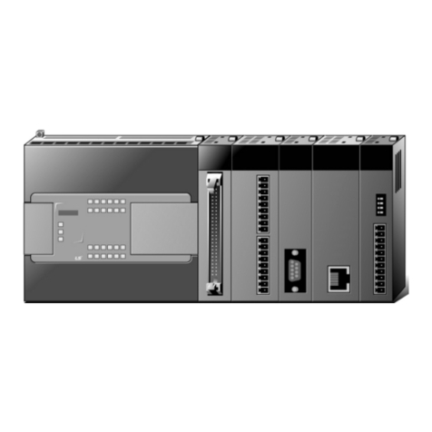
LSIS MASTER-K200S Owner's manual

Instructions & Programming
MASTER-K
z
Read this manual carefully before installing,
wiring, operating, servicing or inspecting this
equipment.
z
Keep this manual within easy reach for
quick reference.

Chapter 1 Introduction
1.1 Introductions ........................................................................................1-1
1.2 Features...............................................................................................1-1

Chapter 1. Introduction
1-1
1Introductions
1.1 Introductions
The chapter 1 ‘Introduction’will provide brief information about the features, functions, and operation of
MASTER-KseriesPLC.
1.2 Features
1) Features of MASTER-K series PLC are as following ;
a) various programming device for easy programming.
b) editing in RUN mode is available
c) supports various open network with international standardcommunication protocol.
d) realization of high processing speed with the dedicated arithmetic processor.
e) various special function modules for PLC application fields.
2) Features of MASTER-K 200S/300S/1000S are as following;
a) The fastprocessing speed :
Realize the lightning processing speed at 0.2㎲with dedicate arithmetic processor.
b) Enhanced self-diagnostic functions :
With detailed self-diagnostic error codes, the cause of error can be identified easily.
c) Debugging operation
The MASTER-K 200S/300S/1000S provides various debugging methods as following and it
enable on-line debugging.
-executionwith commandby command
-execute with the break point designation
-execution according to the status of device
-execution with designated numbers of scan
d) Execution of various program types
The MASTER-K 200S/300S/1000S series provides time-driven interrupt, process-driven
interrupt, and subroutine programs as well as normal scan program.
e) Supports the sampling trace and triggering functions
The compatibility among MASTER-Kseries
1)
The I/O (P) and data (D) registers may differ for each series. Please refer the memory map of each
series at the chapter 2.2 before convert a program for other MASTER-Kseries.
2) Some instructions are not supported by all series. Please refer the instruction table of appendix 9.
3) Please backup the original program before converting the program.
Remark

Chapter 2 Functions
2.1 Performance Specifications.............................................................................2-1
2.1.1 K10S1 / K10S / K30S / K60S........................................................................2-1
2.1.2 K200S / K300S / K1000S..............................................................................2-2
2.2 Memory configurationmap ..............................................................................2-3
2.2.1 K10S1...............................................................................................................2-3
2.2.2 K10S / K30S / K60S.......................................................................................2-4
2.2.3 K200S / K300S / K1000S..............................................................................2-5
2.3 Memory devices of MASTER-Kseries..........................................................2-6
2.3.1 Input / output area : P.....................................................................................2-6
2.3.2 Auxiliary relay : M...........................................................................................2-7
2.3.3 Keep relay : K..................................................................................................2-8
2.3.4 Link relay : L....................................................................................................2-8
2.3.5 Step control relay : S......................................................................................2-8
2.3.6 Timer relay : T.................................................................................................2-9
2.3.7 Counter relay : C...........................................................................................2-10
2.3.8 Data register : D............................................................................................2-11
2.3.9 Indirect assignment data register : #D......................................................2-11
2.3.10 Special relay : F............................................................................................2-12
2.3.11 Special M / L relay : M / L............................................................................2-12
2.3.12 Special data register : D..............................................................................2-12
2.4 Parameter setting..............................................................................................2-13
2.4.1 Watch dog timer setting...............................................................................2-13
2.4.2 Timer area setting .........................................................................................2-13
2.4.3 The latch (non-volatile) area setting..........................................................2-13
2.4.4 Setting the mode of CPU (RUN / STOP) when an error is occurred....2-14
2.4.5 Station number / Baud rate setting ............................................................2-14

2.4.6 High speed counter setting.........................................................................2-15
2.4.7 Interrupt setting .............................................................................................2-15
2.4.8 The reservation of I/O number allocation..................................................2-15
2.4.9 The output of Debug mode.........................................................................2-16
2.5 Operation processing of CPU........................................................................2-17
2.5.1 The repetitive operation...............................................................................2-17
2.5.2 The operation mode of CPU .......................................................................2-18
2.6 Special functions of MASTER-Kseries......................................................2-20
2.6.1 Interrupt functions.........................................................................................2-20
2.6.2 RTC (Real Time Clock) function.................................................................2-24
2.6.3 Forced I/O setting.........................................................................................2-27
2.6.4 Program edit in RUN mode.........................................................................2-28
2.6.5 Self-diagnosis................................................................................................2-29
2.7 Program check ..................................................................................................2-30
2.7.1 JMP –JME.....................................................................................................2-30
2.7.2 CALL , SBRT / RET......................................................................................2-31
2.7.3 MCS –MCSCLR...........................................................................................2-32
2.7.4 FOR –NEXT .................................................................................................2-33
2.7.5 END / RET .....................................................................................................2-34
2.7.6 Dualcoil..........................................................................................................2-34
2.8 Error handling....................................................................................................2-35
2.8.1 RUN / STOP at operation error ..................................................................2-35
2.8.2 Error flag (F110 / F115)................................................................................2-35
2.8.3 LED indication...............................................................................................2-36
2.8.4 Error code list................................................................................................2-37

Chapter 2. Functions
2-1
2Functions
2.1 Performance Specifications
2.1.1 K10S1/ K10S / K30S / K60S
Items K10S1 K10S K30S K60S
Program control method Cyclic execution of stored program
I/O control method Indirect (Refresh) method
Basic 30
Numbers of
Instructions Application 226
Processingspeed 3.2 ~ 7.6㎲/step 1.2 ㎲/step
Programcapacity 800 steps 2,048 steps
P (I/O relay) P0000 ~ P001F
(32 points) P0000 ~ P005F (96 points)
M(Auxiliary relay) M0000 ~ M015F
(256points) M0000 ~ M031F (512 points)
K(Keeprelay) K0000 ~ K007F
(128points) K0000~K015F (256points)
L (Link relay) L0000 ~ L007F
(128points) L0000 ~ L015F (256 points)
F (Special relay) F0000 ~ F015F
(256points) F0000 ~ K015F (256 points)
100ms T000 ~ T031
(32 points) T000 ~ T095 (96 points)
T(Timerrelay) 10ms T032 ~ T047
(16 points)T096 ~ T127 (32 points)
C (Counter relay) C000 ~ C015
(16 points) C000 ~ C127 (128 points)
S (Step controller) S00.00 ~ S15.99
(16×100 steps) S00.00~ S31.99 (32×100 steps)
D (Data register) D0000 ~ D0063
(64 words) D0000 ~ D0255 (256 words)
The range of integer 16 bit : −32768 ~ 32767
32 bit : −2147483648 ~ 2147483647
Timer types On-delay, Off-delay, Accumulation, Monostable, Retriggerable (5 types)
Countertypes Up, Down, Up-down, Ring counter (4 types)
Programming language Mnemonic, Ladder diagram
Special functions Real time clock, High speed counter, RS-485 communication

Chapter 2. Functions
2-2
2.1.2 K200S / K300S / K1000S
Items K200S K300S K1000S
Program control method Cyclic execution of stored program, Time-driven interrupt, Event-driven
interrupt
I/O control method Indirect , Direct by program command
Basic 30
Numbers of
Instructions Application 226 228
Processingspeed 0.5 ㎲/step 0.2 ㎲/step
Programcapacity 7k steps 15k steps 30k steps
P0000 ~
P031F
(512points)
O/S v2.x
or less
P (I/O relay) P0000 ~ P015F
(256points) P0000 ~
P063F
(1,024 points)
O/S v3.0
or later
P0000 ~ P063F
(1,024 points)
M(Auxiliaryrelay) M0000 ~ M191F (3,072 points)
K(Keeprelay) K0000 ~ K031F (512 points)
L (Link relay) L0000 ~ L063F (1,024 points)
F (Special relay) F0000 ~F063F (1,024 points)
T(Timerrelay) 100msec (T000 ~ T191 : 192 points), 10msec (T192 ~ T255 : 64 points)
The range of 100ms and 10ms timer can be changed with parameter setting.
C (Counter relay) C000 ~ C255 (256 points)
S (Step controller) S00.00 ~ S99.99 (100×100 steps)
D (Data register) D0000 ~ D4999 (5,000 words) D0000 ~ D9999 (10,000
words)
The range of integer
1. Signed instruction
16 bit : −32768 ~ 32767
32 bit : −2147483648 ~ 2147483647
2. Unsigned instruction
16 bit : 00000 ~ 65535
32 bit : 00000000 ~ 4295967295
Timer types On-delay, Off-delay, Accumulation, Monostable, Retriggerable (5 types)
Countertypes Up, Down, Up-down, Ring counter (4 types)
Programming language Mnemonic, Ladder diagram
Special functions Real time clock, RUN mode editing, Forced I/O control

Chapter 2. Functions
2-3
2.2 Memory configuration map
2.2.1 K10S1
Bit Data Area Word Data Area User Program Area
I/O relay
(32 points) “P”
Auxiliary relay
(256 points) “M”
Keep relay
(128 points) “K”
Special relay
(256 points) “F”
Link relay
(128 points) “L”
P00
P01
M00
M15
K00
K07
F00
F15
L00
L07
Data Register
(64 words) “D”
D000
D063
Timer Setting Value
(48 words)
T000
T047
T000 Timer Elapsed Value
(48 words)
CounterSetting Value
(16 words)
Counter Elapsed Value
(16 words)
T047
C000
C015
C000
C015
Parameter setting area
Word UserProgram
Area
(800steps)
Timer relay (100ms)
(32 points) “T”
Timer relay (10ms)
(16 points) “T”
Counterrelay
(16 points) “C”
T000
T031
T032
T047
C000
C015
StepController
(16 x100 steps)
S00.00~S15.99
“S”
S00
S15
0~ F 0000 ~ FFFF
Retentive area
Parea None Tarea T024 ~ T031 (10msec)
Karea K000 ~ K07F T044 ~ T047 (100msec)
Larea L00 ~ L07F Carea C012 ~ C015
Darea D048 ~ D063 Sarea S12.00 ~ S15.99

Chapter 2. Functions
2-4
2.2.2 K10S / K30S / K60S
Bit Data Area Word Data Area User Program Area
I/O relay
(96 points) “P”
Auxiliary relay
(512 points) “M”
Keep relay
(256 points) “K”
Special relay
(256 points) “F”
Link relay
(256 points) “L”
P00
P05
M00
M31
K00
K15
F00
F15
L00
L15
Data Register
(256 words) “D”
D000
D255
Timer Setting Value
(128words)
T000
T127
T000 Timer Elapsed Value
(128words)
Counter Setting Value
(128words)
Counter Elapsed Value
(128words)
T127
C000
C127
C000
C127
Parameter setting area
Word UserProgram
Area
(2,048 steps)
Timer relay (100ms)
(96 points) “T”
Timer relay (10ms)
(32 points) “T”
Counterrelay
(128 points) “C”
T000
T095
T096
T127
C000
C127
StepController
(32 x100 steps)
S00.00~S31.99
“S”
S00
S31
0~ F 0000 ~ FFFF
Retentive area
Parea None Tarea T072 ~ T095 (10msec)
Karea K000 ~ K15F T120 ~ T127 (100msec)
Larea L00 ~ L15F Carea C096 ~ C127
Darea D192 ~ D255 Sarea S24.00 ~ S31.99

Chapter 2. Functions
2-5
2.2.3 K200S / K300S / K1000S
Bit Data Area Word Data Area User Program Area
I/O relay
(See the remark) “P”
Auxiliary relay
(3,040 points) “M”
Special auxiliary relay
(32 points) “M”
Keep relay
(512 points) “K”
Special relay
(1,024 points) “F”
Link relay
(1,024 points) “L”
P00
Pxx1
M000
M189
M190
M191
K00
K31
F00
F63
L00
L63
Data Register
“D”
D0000
Dxxxx
2
Dxxxx3Reserved for special usage
Timer Setting Value
(256words)
T000
T255
T000 Timer Elapsed Value
(256words)
Counter Setting Value
(256words)
Counter Elapsed Value
(256words)
T255
C000
C255
C000
C255
Parameter setting area
Word UserProgram
Area
MK1000S :30k steps
MK300S :
15k steps
MK200S : 7k steps
Timer relay (100ms)
192points “T”
Timer relay (10ms)
64 points “T”
Counterrelay
256 points “C”
T000
T191
T192
T255
C000
C255
StepController
(100x100steps)
S00.00~S99.99
“S”
S00
S99
Pxx1Dxxxx2Dxxxx3
MK1000S P63 (1,024 pts) D9500 D9999
MK300S P63 (1,024 pts)
MK300S P31 (512 pts)
MK200S P15 (256 pts)
D4500 D4999
Remark
0~ F 0000 ~ FFFF

Chapter 2. Functions
2-6
2.3 Memory devices of MASTER-K series
2.3.1 Input / output area : P
The P devices are used for data transaction between the PLC CPU and external devices.
The input devices hold ON/OFF data sent from external devices (e.g. pushbuttons, select
switches, limit switches, digital switches, etc.) to input module. Input data is used by the
program as contact data (NO1and NC contacts) and as the source data for basic and
application instructions.
The output devices are used to output operation results of the program from the output module
to external devices (e.g. solenoids, magnetic switches, signal lamps, digital indicators). Only NO
contact type is available for output devices.
The redundant P devices that are not connected to external devicescan be used in the same
way with the auxiliary relay M.
< Figure 1. The example of input/output configuration >
The input signals are stored in batch in the input data memory before execution of each scan.
The data in the input data memory is used for execution of the sequence program operation.
The operation results are output by each result to the output data memory. The data in the
output data memory is output in batch to the output modules after execution of the END
instruction. Please make sure that there is no conflict of input and output in the user program
because the MASTER-K series uses a P area for input and output in common.
1NO :Normally Open contact, NC : NormallyClosed contact
P0023
( )
P0002
P0021
P0024
( )
P0021
P0020
( )
P0021
( )
P0000
P0001 P0020
P0000
P0001
P0002
Input
P0020
P0021
P0023 Output
P0024

Chapter 2. Functions
2-7
< Figure 2. Flow of input / output data in the refresh mode >
-Input refresh
Input datais read (①) in batch from the input module before execution of step 0 and stored
in the input data memory.
-When an input contact command is executed :
Input data is read (②) from the input data memory and used for execution of the sequence
program.
-When an output contact command is executed :
Output data is read (③) from the output data memory and used for execution of the
sequence program.
-When an output OUT instruction is executed :
The operation result (④) is stored in the output data memory.
-Output refresh
Data (⑤) in the output data memory is output in batch to the output module after execution
of the END instruction.
2.3.2 Auxiliary relay : M
The M area is internal relay used in the PLC CPU, and can not be connected directly with
external devices. All M area except designated as latched area will be cleared as 0 when the
PLC is switched on or turned to RUN mode. With K200S / K300S / K1000S, a user can change
the latched area by parameter setting.
CPU InputP
Datamemory
Output P
Datamemory
Input
module
Output
module
①Read
⑤Write
CPU module
②Read
④Write
③Read
P0021
( )
P0000
P0001 P0020
P0020
( )

Chapter 2. Functions
2-8
2.3.3 Keep relay : K
The K area functions as same as M area. However, the operation results are retained if the PLC
is switched on or turned to RUN mode. The K area can be cleared by following methods;
-put the initialization routine in the sequence program.
-Run the data clear function of hand-held loader (KLD-150S)
-Run the data clear function of graphic loader (KGL-WIN)
2.3.4 Link relay : L
The L area is the internal memory for use in a data or computer link system. It can be used as
same as M area if no link module is mounted on the PLC system. With K200S / K300S /
K1000S, it is possible to change the range of latch area by parameter setting. For the detail
usage of L area, please refer the list of link relay at appendix and the computer link user’s
manual.
2.3.5 Step control relay : S
The S area can be used for two kinds of step control according to the instruction –OUT or SET.
If the OUT instruction is used, the S area functions as last-in priority. Otherwise, it functions as
sequential control. (See the chapter 4 for detailed usage.)
When the CPU is switched on or turned to RUN mode, the S area will be initialized as first step
(Sxx.00) except the latch area designated by parameter setting.
OUT S00.02
OUT S00.29
OUT S00.61
In the same group, the last-
in condition has the
priority to run.
SET S00.01
SET S00.02
SET S00.03
Sequential control means that a certain process
can be executed on
ly after the previous process
iscompleted.
SET S00.04
SET S00.00
The clear condition (Sxx.00 ) can be operated at
any time while the sequential process is
running.

Chapter 2. Functions
2-9
2.3.6 Timer relay : T
MASTER-K series have 100msec and 10msec timer. The timing method is various according to
the timer instructions (TON, TOFF, TMR, TMON, TRTG). The maximum timer setting value is
hFFFF by hexadecimal or 65535 by decimal. The following figure shows the types and timing
methods of each timer instruction.
< Figure 3. Types and timing methods of timer instructions >
Timer
instruction Description Timing
method Time chart
TON ON Delay Increment
TOFF OFF Delay Decrement
TMR Accumulation
ON Delay Increment
TMON Monostable Decrement
TRTG Retriggerable Decrement
Timer
instruction
No. of timer relay
Inputcontact
Setting value
ON Delay timer
Input
condition
t
t =setting value
OFF Delay timer
t
Accumulation
timer
t1
t2
t = t1 + t2
Monostabletimer
t
Retriggerable timer
t
Timer
output
Input
condition
Timer
output
Timer
output
Timer
output
Timer
output
Input
condition
Input
condition
Input
condition
t =setting value
t =setting value
t =setting value
t =setting value

Chapter 2. Functions
2-10
2.3.7 Counter relay : C
The counter counts the rising edges of pulses driving its input signal and counts once only when
the input signal is switched from off to on. MASTER-K series have 4 counter instructions such
as CTU, CTD, CTUD, and CTR. The maximum counter setting value is hFFFF ( = 65535). The
followings shows brief information for counter operation.
< Figure 4. Types and counting methods of counter instructions >
Counter
instruction Type Counting
method Input
signal Time chart
CTU Up
Counter Increment 1
CTD Down
counter Decrement 1
CTUD Up/Down
Counter Increment /
Decrement 2
CTR Ring
counter Increment 1
Rising Edge (OFF
à
ON)
U CXX CXXX
R <S> XXXX
Setting
value
Reset signal
CountPulse
Elapsedvalue
Counteroutput
Increasepulse
Decreasepulse
Setting
value
Setting
value
Reset signal
CountPulse
Elapsedvalue
Counteroutput
Elapsedvalue
Counter output
Reset signal
Reset signal
CountPulse
Elapsedvalue
Counteroutput
Setting
value
Reset signal
CountPulse

Chapter 2. Functions
2-11
2.3.8 Data register : D
The D area is used to store numeric data. Each data register consists of 16 bits (1 word) which
is the unit of data read and write.
The data resister number designated by the double-word instruction holds the lower 16 bits and
the designated data register number + 1 holds the higher 16 bits.
Example)
D51 D50
h1234 h5678
The D area except latched area assigned by parameter setting will be cleared as 0 when the
CPU is switched on or turned to RUN mode.
2.3.9 Indirectassignment data register : #D
#D is used for indirect addressing of the D area. The contained value of data register assigned
with‘#’symbol points the real address of data register at which the result of operation is stored.
If #D is used with a double-word instruction, the lower 16 bits will stored at the data resister
number designated by the contained value of #D, and higher 16 bits will stored at the data
resister number + 1.
Example)
DMOV h12345678 D050
High 16 bits Lower 16 bits
MOV D000 #D1023
h7893
h03E8(1000)
(Hexvalue)
(No. of data register)
D0000
D1000
D1023
The actual data movement
Indirect addressing (#D0123)
If the value of data register assigned at # D exceeds the physical address range of D area, the operation error
flag(F110)willbesetandtherelevantinstructionwillbeignored.
Remark

Chapter 2. Functions
2-12
2.3.10 Special relay : F
The F area is read-only relay and user can not change the value of F area. See the F relay table
at the appendix for details.
2.3.11 Special M / L relay : M / L
Some M or L relays are reserved for special usage. See the list of special relays at the appendix
and be careful when use those M or L area in the program.
2.3.12 Special data register : D
Some data registers are reserved for special usage. These registers are various according to
the type of CPU. See the list of special registers at the appendix and be careful when use those
data register in the program.

Chapter 2. Functions
2-13
2.4 Parameter setting
2.4.1 Watch dog timer setting
(Applicable to K80S / 200S / K300S / K1000S only)
Setting range : 10msec ~ 6000msec
Setting unit : 10msec
The default value of watch dog timer is 200msec. The watch dog timer of K10S1, K10S, K30S,
and K60S is fixed as 200msec.
2.4.2 Timer area setting
(Applicable to K80S / 200S / K300S / K1000S only)
Timing unit Setting range Default
100ms T000 ~ T255 T000 ~ T191
10ms T000 ~ T255 T192 ~ T255
By setting the 100msec timer area, the 10msec timer area is automatically set as the rest of
area.
2.4.3 The latch (non-volatile) area setting
(Applicable to K80S / 200S / K300S / K1000S only)
The latch area designated by parameter setting will hold the result of operation when the CPU is
switched on or turned to RUN mode.
The latch area of K10S1/K10S/K30S/K60S is fixed and cannot be changed. Please refer the
Chapter 2.2 for memory configuration.
Device Settingrange Defaultrange
MM0000~M191F
LL0000~L063F None
T(100ms) T0000~T0191 * T144~191 *
T(10ms) T0192~T0255 * T240~T255*
CC0000~C0255 C192~C255
K1000S D0000~D9999 D6000~D8999
K300SD
K200S D0000~D4999 D3500~D4500
SS00.00~S99.99 S80~S99
* The setting range of timer can be changed by 100msec / 10msec timer range setting.

Chapter 2. Functions
2-14
2.4.4 Setting the mode of CPU (RUN / STOP) when an error is occurred
(Applicable to K80S / 200S / K300S / K1000S only)
When a non-critical error such as fuse blown or operation error, the CPU will keep running or
stop operation according to the parameter setting. See the following table for details.
(K10S1/K10S/K30S/K60S is set as the default setting of K200S/300S/1000S.)
* = Default setting
Errortype Description Mode RUN
LED Errorflag
Fuseblown The fuse of output or hybrid module is
blown
RUN * /
STOP
ON * /
OFF F035
Operation
Error
BCD error
The result of BCD conversion is
exceeds the specified range (9999 or
99999999)
Overrangeerror
One or more operands exceed the
specified device range.
RUN * /
STOP
ON * /
OFF
F110
F115
The F110 bit is updated after each instruction is completed. Therefore, even an operation error
was occurred, the F110 will be cleared if the next instruction is completed normally. In other
hand, the F115 will be set when an operation error occurs and keep the on status until user
cleared the F115 with CLE instruction.
2.4.5 Station number / Baud rate setting
(Applicable for K10S1 / K10S / K30S / K60S / K80S / K200S)
PLC type Protocol Station
number Baud rate Descriptions
K10S1
K10S
K30S
K60S
RS-485 0 ~ 31
(h00 ~ h1F)
300, 600, 1200, 2400,
4800, 9600, 19200 bps
K80S RS-232 / RS-48510 ~ 31 1200 ~ 57600 bps
K200S-ARS-2322N/A 1200 ~ 57600 bps
K200S-B/C RS-42230 ~ 31 1200 ~ 57600 bps
110-points main unit only.
2K3P-07AS
3K3P-07BS / K3P-07CS

Chapter 2. Functions
2-15
2.4.6 High speed counter setting
(Applicable for K10S1, K10S, K30S, K60S)
The block type models of MASTER-K series include the high speed counter function in the main
module. When the ‘HSCNT’instruction is used, the high speed counter parameters should be
set with KGL-WIN or KLD-150S. Refer the 5.22.1 ‘HSCNT’instruction part.
2.4.7 Interrupt setting
(Applicable for K80S / 200S / K300S / K1000S)
1) The priority of interrupts setting
Each of interrupts has a priority level. If two or more interrupts occur at the same time, the CPU
will process the interrupt that has higher priority. Priority levels are described by numbers, and
smaller number means higher priority.
2) TDI (Time driven interrupt)
TDI is the interrupt that occurs periodically. The period of interrupt can be set with parameters
by 10-msec unit. The longest period is 60 seconds.
3) PDI (Process driven interrupt)
PDI is the interrupt that occurs when an input of interrupt module was turned on.
Refer the chapter 2.6.1 for more details.
2.4.8 The reservation of I/O number allocation
(Applicable for K200S / K300S / K1000S)
The I/O number is allocated automatically by CPU module according to the actual status of
module. However, user can reserve I/O number allocation with parameter setting, then it makes
a user keep a sequence program in case of module fault or replacement.
1) User can assign the type of module (input, output, or special module) and I/O occupation
number to each module.
2) If the reserved I/O number is larger than the I/O number of actual module, the redundant
reserved I/O points are used as internal relay. Otherwise, the redundant actual I/O points are
disabled.
3) Non-reserved slots occupy I/O points as the I/O points of actual module, and special
modules occupy 16 I/O points.
This manual suits for next models
7
Table of contents
Other LSIS Controllers manuals

LSIS
LSIS XP10BKA/DC User manual

LSIS
LSIS LSLV-S100 Series User manual

LSIS
LSIS XGT Series User manual

LSIS
LSIS XGT Series User manual

LSIS
LSIS XEC-DN32U User manual

LSIS
LSIS XGT Series User manual

LSIS
LSIS XEC-DN32H/DC User manual

LSIS
LSIS SV-iS7 series User manual

LSIS
LSIS Master-K K200S User manual

LSIS
LSIS XGT Series User manual

LSIS
LSIS XBM-DN16S User manual

LSIS
LSIS XDL-L7SA002X User manual

LSIS
LSIS XBC-DR20SU User manual

LSIS
LSIS XEC-DR32H User manual

LSIS
LSIS XGL-CH2A User manual

LSIS
LSIS XDL-L7NH Series User manual

LSIS
LSIS XGT Series User manual

LSIS
LSIS XGT Series User manual

LSIS
LSIS XBF-AD04A User manual
LSIS
LSIS XGL-EFMT User manual