Sorel XHCC User manual

Read carefully before installation, commissioning and operation
System Controller XHCC
Installation and operating instructions

A. - Safety instructions 3
A.1. - EC declaration of conformity 3
A.2. - General instructions 3
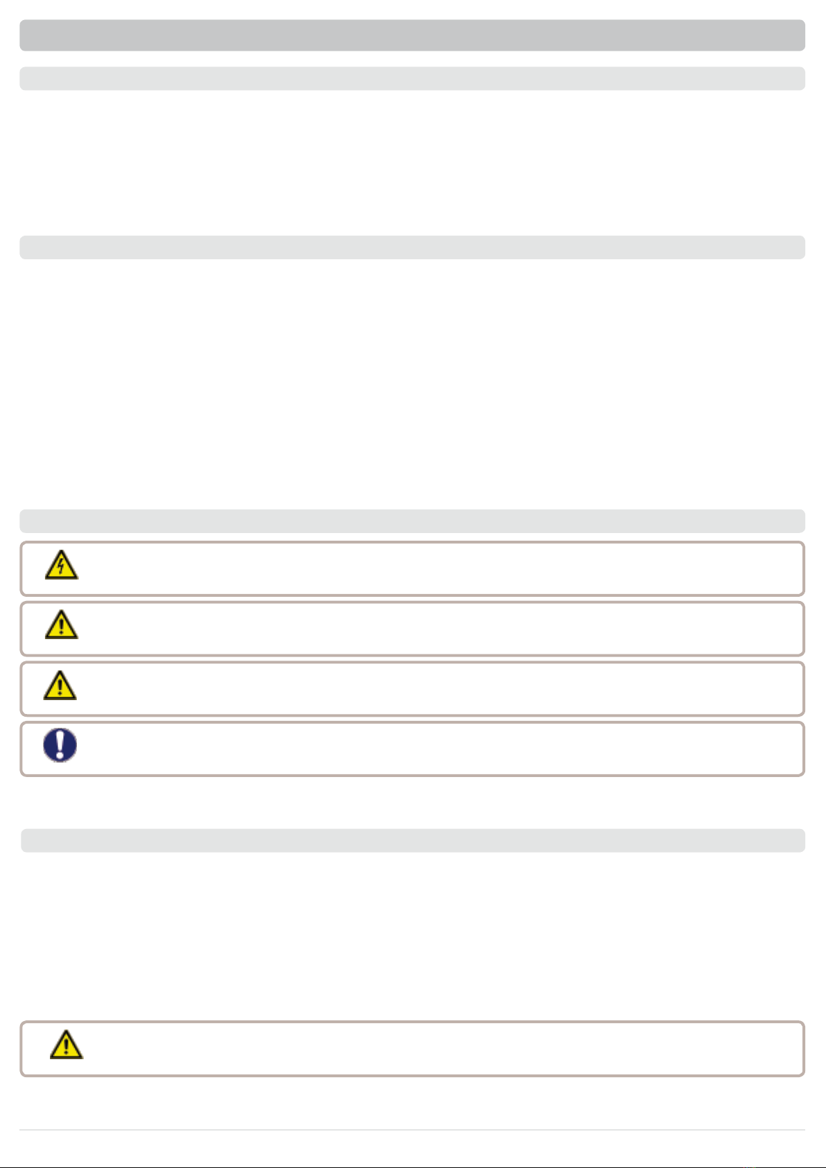
A.3. - Explanation of symbols 3
A.4. - Changes to the unit 3
A.5. - Warranty and liability 4
A.6. - About the controller 4
A.7. - Scope of supply 4
A.8. - Disposal and pollutants 4
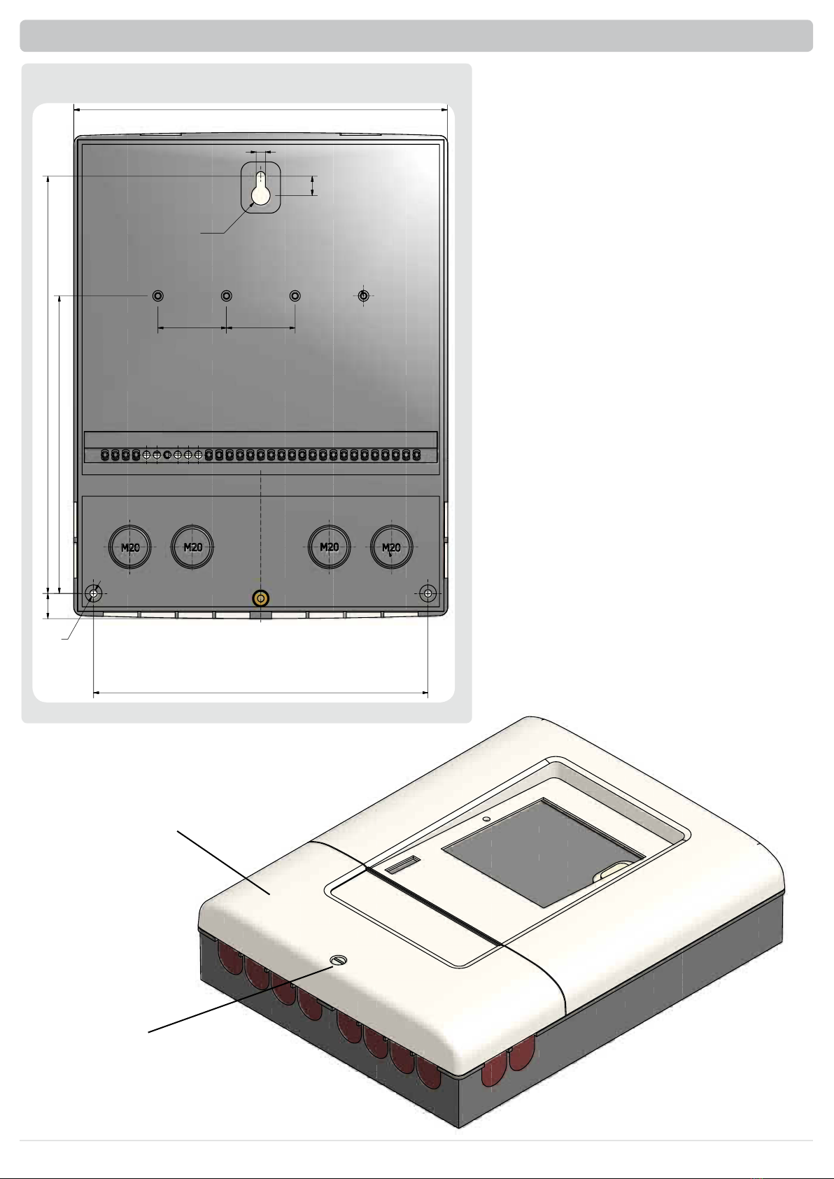
B. - Description of controller 5
B.1. - Speci cations 5
B.2. - Temperature resistance table for Pt1000 sensors 5
C. - Installation 6
C.1. - Wall installation 6
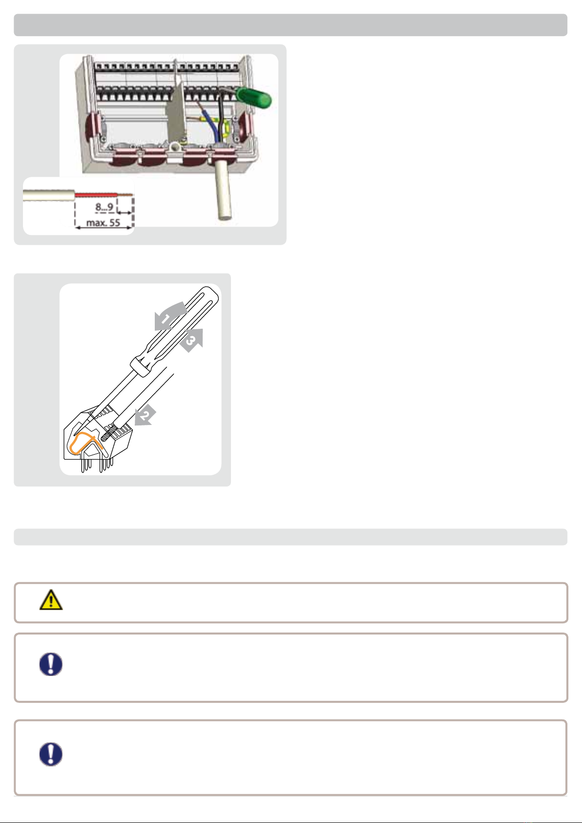
C.2. - Electrical connection 6
C.3. - Installing the temperature sensors 8
D. - Terminal connection 9
D.1. - Terminal connection 9
D.2. - Terminal connection diagram 9
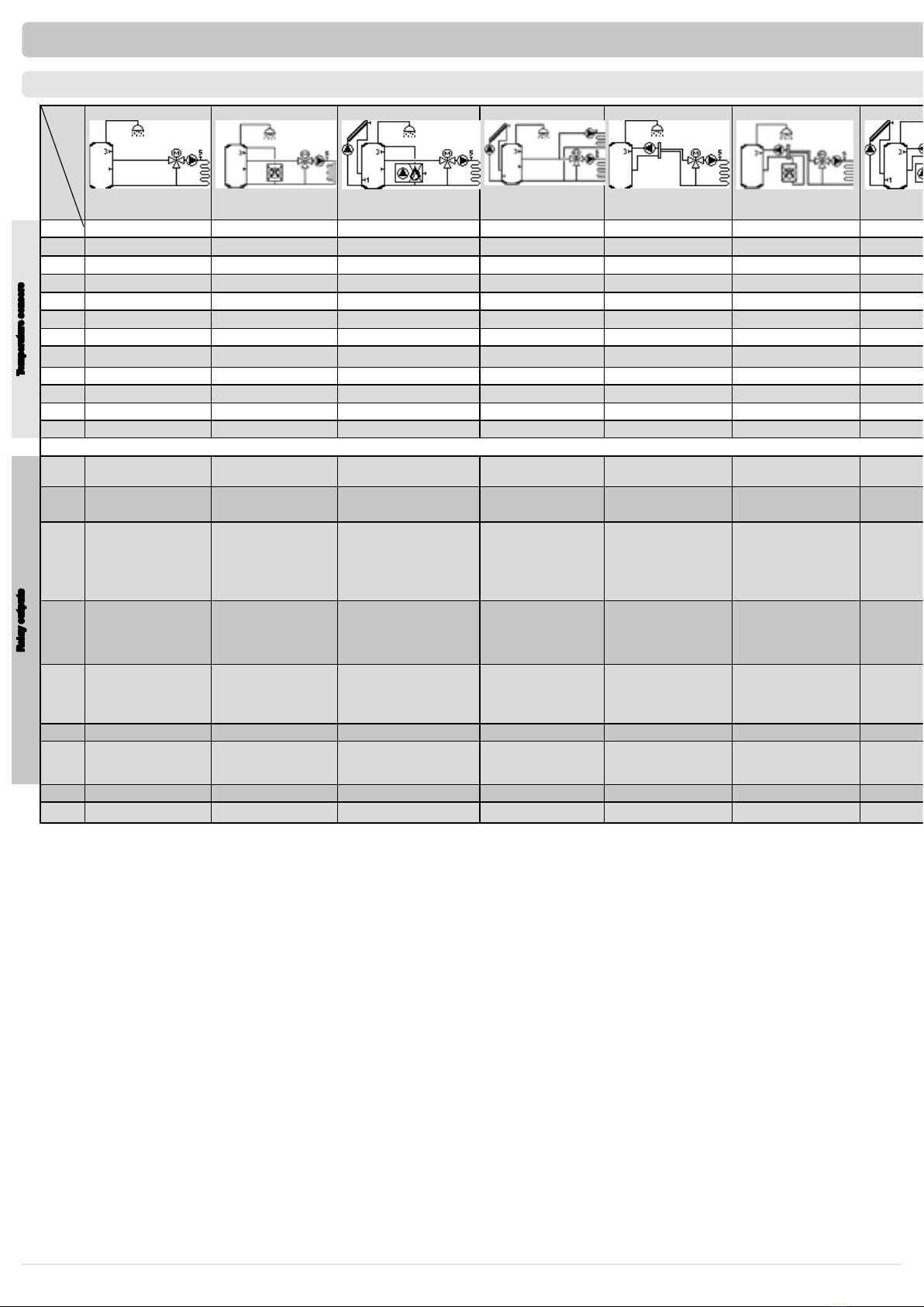
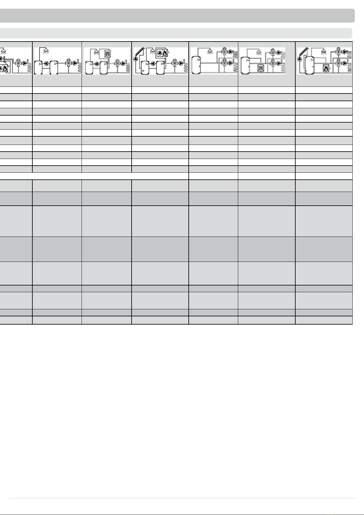
D.3. - Hydraulic variants / Systems / Diagrams 10
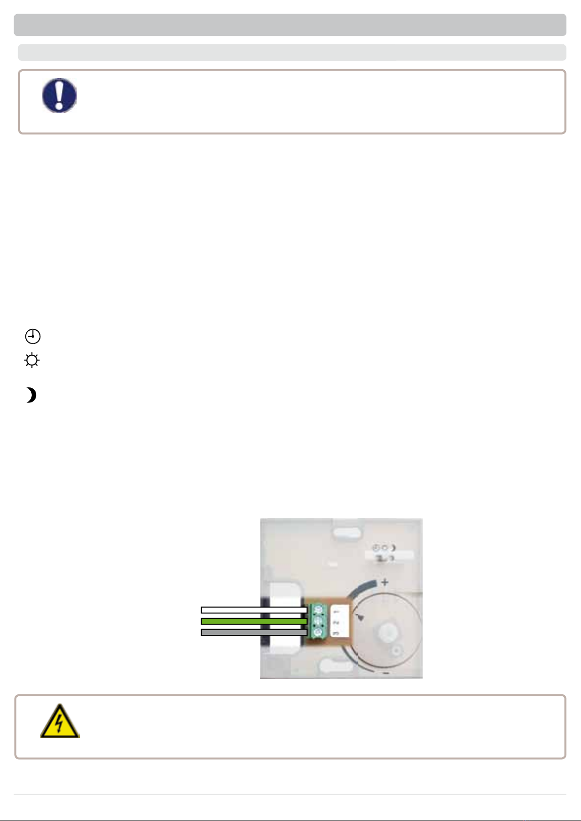
D.4. - RC 21 Room thermostat and remote adjuster 12
E. - Operation 13
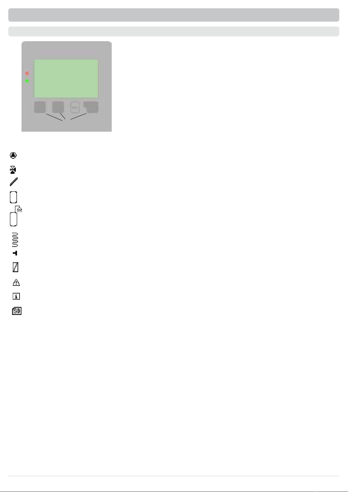
E.1. - Display and input 13
E.2. - Commissioning help 14
E.3. - Free commissioning 14
E.4 - Menu sequence and menu structure 15
1. - Measurement values 16
2. - Statistics 17
2.1. - Today 17
2.2. - 28 days 17
2.3. - Operating hours 17
2.4. - Heat quantity 17
2.5. - Graphic overview 17
2.6. - Message log 17
2.7. - Reset/clear 17
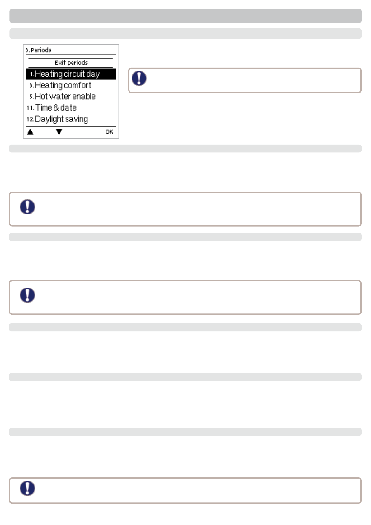
3. - Periods 18
3.1. - Heating circuit day 18
3.2. - Heating circuit 2 day 18
3.3. - Heating comfort 18
3.4. - Heating circuit 2 comfort 18
3.5. - Hot water enable 18
3.6. - Cooling periods 19
3.7. - Thermostat 19
3.8. - Circulation 19
3.9. - Antilegionella 19
3.10. - Time and Date 19
3.11. - Daylight saving time 19
4. - Operating Modes 20
4.1. - Heating circuit 20
4.2. - Manual 20
4.3. - Domestic Hot Water 20
5. - Settings 21
5.1. - Difference 21
5.2. - Heat Transfer 21
5.3. - Booster pump 21
5.4. - Thermostat 21
5.5. - Cooling 21
5.6. - Heating circuit 21
5.6.1. - Summer / Winter Day 21
5.6.2. - Summer / Winter Night 21
5.6.3. - Curve 22
5.6.4. - Day correction 22
5.6.5. - Night correction 22
5.6.6. - Comfort temperature boost 22
5.6.7. - Minimum Flow 23
5.6.8. - Maximum Flow 23
5.6.9. - Reference/actual - 23
5.6.10. - Reference/actual + 23
5.6.11. - Storage HC 23
5.7. - Solid fuel boiler 23
5.8. - Settings Domestic Hot Water (DHW) 23
5.8.1. - Hot water Minimum 23
5.8.2. - DHW reference 24
5.8.3. - DHW Hysteresis 24
5.8.4. - Buffer DHW charge 24
5.8.5. - DHW Priority 24
5.9. - Solar 24
5.10. - Solarbypass 24
5.11. - Heat exchanger 24
5.12. - Burner 24
5.13. - Boiler pump 24
5.14. - Compressor 24
5.15. - Glycol pump 24
5.16. - Storage loading pump 24
5.17. - Heating circuit 2 24
5.18. - Return ow increase 24
5.19. - Circulation 24
5.20. - Error messages 25
5.21. - Pressure control 25
5.22. - Parallel operation R1 25
5.23. - Parallel operation R2 25
5.24. - Mixer 25
5.24.1. - Turn time 25
5.24.2. - Pause factor 25
5.24.3. - Increase 25
5.25. - Room controller 25
5.25.1. - Room controller 25
5.25.2. - Room reference day 25
5.25.3. - Room reference night 25
5.25.4. - RC in uence 25
6. - Protective functions 26
6.1. - Anti-seizing protection 26
6.2. - Frost protection 26
6.3. - Antilegionella 27
6.3.1. - AL T set 27
6.3.2. - AL residence time 27
6.3.3. - Last AL heat up 27
6.3.4. - AL sensor 1 27
6.3.5. - AL Sensor 2 27
6.3.6. - AL-times 27
6.4. - Protective functions for Solar 28
6.5. - System protection 28
6.6. - Collector protection 28
6.6.1. - Recooling 28
6.6.2. - Frost protection 29
6.7. - Seizing protection 29
6.8. - Collector alarm 29
6.9 - Buffer Discharge protection 29
7. - Special functions 30
7.1. - Program selection 30
7.2. - Speed control 30
7.2.1. - Variant 30
7.2.2. - Type of pump 31
7.2.3. - Pump menu 31
7.2.3.1. - Pump 31
7.2.4. - Purging time 31
7.2.5. - Sweep time 31
7.2.6. - max. speed 31
7.2.7. - min. speed 31
7.3. - Relay functions 32
7.3.1. - Difference 32
7.3.1.1. - Difference 32
7.3.1.2. - ∆ T Difference 32
7.3.1.3. - DF source (sensor) 32
7.3.1.4. - Diff Tmin 32
7.3.1.5. - DF Drain (sensor) 32
7.3.1.6. - Diff Tmax 32
7.3.2. - Heat transfer 33
7.3.2.1. - ∆ T Heat transfer 33
7.3.2.2. - Setpoint 33
7.3.2.3. - HT Tmin 33
7.3.2.4. - HT Source (sensor) 33
7.3.2.5. - HT Drain (Target sensor) 33
7.3.3. - Booster pump 33
7.3.3.1. - Booster 33
7.3.3.2. - Fill time 33
7.3.4. - Thermostat 34
7.3.4.1. - Thermostat 34
7.3.4.2. - TH Set 34
7.3.4.3. - TH hysteresis 34
7.3.4.4. - Thermostat sensor 1 34
7.3.4.5. - Thermostat sensor 2 34
7.3.4.6. - T eco 34
7.3.4.7. - Energy saving mode 34
7.3.4.8. - Periods 34
7.3.5. - Cooling 35
7.3.5.1. - Cooling 35
7.3.5.2. - Co Tref 35
7.3.5.3. - Hysteresis 35
7.3.5.4. - Delay 35
7.3.5.5. - Cooling sensor 35
7.3.5.6. - Cooling periods 35
7.3.6. - Solid fuel boiler 36
7.3.6.1. - Solid fuel boiler 36
7.3.6.2. - SF Tmax 36
7.3.6.3. - SF Tmin 36
7.3.6.4. - ∆ T SF 36
7.3.6.5. - Boiler sensor 36
7.3.6.6. - Storage sensor 36
7.3.7. - Solar 37
7.3.7.1. - Solar 37
7.3.7.2. - Tmin S (X) 37
7.3.7.3. - ∆ T Solar S (X) 37
7.3.7.4. - Tmax S (X) 37
7.3.7.5. - Start aid function 37
7.3.7.6. - Protective functions 37
7.3.8. - Solar bypass 38
7.3.8.1. - Solar bypass 38
7.3.8.2. - Variant 38
7.3.8.3. - Bypass sensor 38
7.3.9. - Heat exchanger 38
7.3.9.1. - Heat exchanger 38
7.3.9.2. - HE sensor 38
7.3.10. - Burner 39
7.3.10.1. - Burner 39
7.3.10.2. - DHW request 39
7.3.10.3. - HC request 39
7.3.10.4. - Antilegionella 39
7.3.10.5. - Burner sensor 39
7.3.10.6. - Delay 39
7.3.10.7. - T eco DHW 39
7.3.10.8. - Burner offset 39
7.3.10.9. - Eco mode (during solar charge) 39
7.3.10.10. - Heating circuit offset 39
7.3.10.11. - BP Tmax 39
7.3.11. - Boiler pump 40
7.3.11.1. - Boiler pump 40
7.3.11.2. - BP Tmin 40
7.3.12. - Compressor 41
7.3.12.1. - Compressor 41
7.3.12.2. - DHW request 41
7.3.12.3. - HC request 41
7.3.12.4. - Heat pump run time 41
7.3.12.5. - Heat pump idle time 41
7.3.12.6. - Heat pump delay 41
7.3.12.7. - Periods 41
7.3.13. - Loading pump 41
7.3.13.1. - Loading pump 41
7.3.13.2. - Loading pump lag 41
7.3.14. - Glycol pump 41
7.3.14.1. - Glycol pump 41
7.3.14.2. - Gylcol pump lag 41
7.3.15. - Heating circuit 2 42
7.3.15.1. - Heating circuit 2 42
7.3.15.2. - S/W Day 42
7.3.15.3. - S/W Night 42
7.3.15.4. - Variant 42
7.3.15.5. - Curve 42
7.3.15.6. - Day correction 43
7.3.15.7. - Night correction 43
7.3.15.8. - Comfort temperature boost 43
7.3.15.9. - Minimum Flow 44
7.3.15.10. - Maximum Flow 44
7.3.15.11. - Reference/actual - 44
7.3.15.12. - Reference/actual + 44
7.3.15.13. - Outdoor sensor 44
7.3.15.14. - Flow sensor 44
7.3.16. - Return ow increase 45
7.3.16.1. - Return ow increase 45
7.3.16.2. - RF Tmin 45
7.3.16.3. - RF Tmax 45
7.3.16.4. - ∆T return ow 45
7.3.16.5. - Return ow (sensor) 45
7.3.16.6. - Storage (sensor) 45
7.3.17. - Domestic hot water valve 45
7.3.18. - Circulation 46
7.3.18.1. - Circulation 46
7.3.19.1. - Circulation Tmin 46
7.3.19.2. - Circulation hysteresis 46
7.3.19.3. - Circulation sensor 46
7.3.19.4. - Circulation pause time 46
7.3.19.5. - Purging time 46
7.3.19.6. - Circulations periods 46
7.3.19. - Messages 46
7.3.20. - Pressure monitor 47
7.3.20.1. - Pressure monitor 47
7.3.20.2. - RPS1 / RPS2 47
7.3.20.3. - Pmin 47
7.3.20.4. - Pmax 47
7.3.21. - Parallel operation R1 47
7.3.21.2. - Parallel operation R (X) 47
7.3.21.1. - Delay 47
7.3.21.3. - Followup time 47
7.3.23. - Always on 47
7.3.22. - Parallel operation R2 47
7.3.24. - Heat quantity 48
7.3.24.1. - Flow sensor (X) 48
7.3.24.2. - Return sensor 48
7.3.24.3. - Anti freeze type 48
7.3.24.4. - Glycole percentage 48
7.3.24.5. - Flow rate (X) 48
7.3.24.6. - Offset ∆ T 48
7.3.24.7. - VFS (X) 48
7.3.24.8. - VFS - Position 48
7.3.24.9. - Reference sensor 48
7.3.25. - Pressure monitor 49
7.3.26. - Pressure monitor 49
7.3.26.1. - RPS1 / RPS2 49
7.3.26.2. - Pmin 49
7.3.26.3. - Pmax 49
7.4. - Sensor calibration 49
7.5. - Commissioning 49
7.6. - Factory settings 49
7.7. - SD-Card 50
7.7.1. - Logging 50
7.7.2. - Free storage 50
7.7.3. - Load con guration 50
7.7.4. - Save con guration 50
7.7.5. - Firmware update 50
7.7.6. - Unmount 50
7.8. - Sleep mode 50
8. - Menu lock 51
9. - Service values 51
10. - Language 51
Z.1. Malfunctions with error messages 52
Z.2 Replacing the fuse 53
Z.3 Maintenance 53
K. - Appendix 54
K.1. - Pump 54
K.1.1. - Output Signal 54
K.1.2. - PWM off 54
K.1.3. - PWM on 54
K.1.4. - PWM Max 54
K.1.5. - 0-10V off 54
K.1.6. - 0-10V on 54
K.1.7. - 0-10V Max 54
K.1.8. - Speed when „On“ 54
K.1.9. - Show signal 54
Useful notes / Tips and tricks 56
Content

3
Safety instructions
By af xing the CE mark to the unit the manufacturer declares that the „X Heating Circuit Controller“, hereinafter refererred to
as XHCC, conforms to the relevant safety regulations EC low voltage directive 2006/95/EC as well as the EC directive for elec-
tromagnetic compatibility 2004/108/EC.
Conformity has been veri ed and the corresponding documentation and the EC declaration of conformity are kept on le by the
manufacturer.
A.1. - EC declaration of conformity
These installation and operating instructions contain basic instructions and important information regarding safety, installa-
tion, commissioning, maintenance and the optimal use of the unit. Therefore these instructions must be read completely and
understood by the installation technician/specialist and by the system user before installation, commissioning and operation of
the unit.
The valid accident prevention regulations, VDE regulations, the regulations of the local power utility, the applicable DIN-EN
standards and the installation and operating instruction of the additional system components must also be observed. The con-
troller does not under any circumstances replace any safety devices to be provided by the customer!
Installation, electrical connection, commissioning and maintenance of the unit may only be carried out by specialists who pos-
sess the appropriate training.
For the user: Make sure that the specialist gives you detailed information on the function and operation of the controller. Always
keep these instructions in the vicinity of the controller.
A.2. - General instructions
Danger
Caution
A.3. - Explanation of symbols
Failure to observe these instructions can result in danger to life from electric voltage.
Danger
Failure to observe these instructions can result in serious damage to health such as scalding, or even
life-threatening injuries.
Caution
Failure to observe these instructions can result in destruction of the unit or the system, or damage to the
environment.
Information which is especially important for the function and optimal use of the unit and the system.
A.4. - Changes to the unit
• Changes, additions to or conversion of the unit are not permitted without the written permission from the manufacturer
• It is likewise forbidden to install additional components that have not been tested together with the unit
• If it becomes clear that safe operation of the unit is no longer possible, for example because of damage to the housing,
then turn the controller off immediately
• Any parts of the unit or accessories that are not in perfect condition must be exchanged immediately
• Use only original spare parts and accessories from the manufacturer
• Markings made on the unit at the factory must not be altered, removed or made illegible
• Only the settings actually described in these instructions may be made on the controller
Changes to the unit can compromise the safety and function of the unit or the entire system.
Danger

4
Safety instructions
The controller has been manufactured and tested with regard to high quality and safety requirements. The unit is subject to the
statutory guarantee period of two years from the date of sale.
The warranty and liability shall not include, however, any injury to persons or material damage that is attributable to one or
more of the following causes:
- Failure to observe these installation and operating instructions
- Improper installation, commissioning, maintenance and operation
- Improperly executed repairs
- Unauthorised structural changes to the unit
- Installation of additional components that have not been tested together with the unit
- Any damage resulting from continued use of the unit despite an obvious defect
- Failure to use original spare parts and accessories
- Use of the device for other than its intended purpose
- Operation above or below the limit values listed in the speci cations
- Force majeure
A.5. - Warranty and liability
The System Controller XHCC facilitates ef cient use and function control of your solar or heating system. The device is im-
pressive most of all for its functionality and simple, almost self-explanatory operation. For each step in the input process the
individual entry keys are assigned to appropriate functions and explained. The controller menu contains headwords for the
measured values and settings, as well as help texts or clearly-structured graphics.
The XHCC can be used as a system controller for the various system variants illustrated and explained under „D.3. - Hydraulic
variants / Systems / Diagrams“ on page 10.
Important characteristics of the XHCC:
- Depiction of graphics and texts on an backlit display
- Simple viewing of the current measurement values
- Analysis and monitoring of the system by means of statistical graphics etc.
- Individual con guration of special functions
- Extensive setting menus with explanations
- Menu block can be activated to prevent unintentional setting changes
- Resetting to previously selected values or factory settings
- A wide range of additional functions are available
A.6. - About the controller
- System controller XHCC
- 3 screws 3,5x35mm and 3 plugs 6mm for wall installation
- 12 strain relief clips with 24 screws, replacement fuse 1x T2A / 250V, 1x T630mA / 250V
- Installation and instructions manual XHCC
- Micro SD Card
Optionally contained depending on design/order:
- 2-3 PT1000 temperature sensors and immersion sleeves
- Ethernet
Additionally available:
- Pt1000 temperature sensor, immersion sleeves, overvoltage protection,
- CAN Bus Data Logger
- RC21 Room thermostat with remote adjuster
A.7. - Scope of supply
A.8. - Disposal and pollutants
The unit conforms to the European RoHS directive 2011/65/EU for the restriction of the use of certain hazardous substances in
electrical and electronic equipment.
Caution
The unit must not under any circumstances be disposed of with ordinary household refuse. Dispose of the unit only
at appropriate collection points or ship it back to the seller or manufacturer.

5
Description of controller
B.1. - Specications
Electrical specications:
Mains voltage 100 - 240VAC
Mains frequency 50...60Hz
Power consumption 0.5 - 3 W
Switched power
Entire switched power for electronic relays R1 - R2: 460VA for AC1 / 240W for AC3
Electronic relay R1 min.5W...max.120W for AC3
Electronic relay R2 min.5W...max.120W for AC3
Entire switched power for mechanical relays R3 - R6: 460VA for AC1 / 460W for AC3
Mechanical relay R3 460VA for AC1 / 460W for AC3
Mechanical relay R4 460VA for AC1 / 460W for AC3
Mechanical relay R5 460VA for AC1 / 460W for AC3
Mechanical relay R6 460VA for AC1 / 460W for AC3
potentialfree relay R7 460VA for AC1 / 460W for AC3
0..10V Output for 10 k Ω working resistance
PWM Output Freq. 1 kHz, level 10 V
Internal fuse T630mA / 250V slow blow (x3)
4x T2A / 250V slow blow (x1)
Protection category IP40
Protection class II
Sensor inputs 8 x Pt1000
2x Grundfos Direct Sensors
1x RC21/RC22
Measuring range
PT1000 -40°C to 300°C
Grundfos Direct Sensor: 0°C-100°C (-25°C /120°C short term)
1 l/min - 12 l/min (VFS1-12)
2 l/min - 40 l/min (VFS2-40)
5 l/min - 100 l/min (VFS5-100)
10 l/min - 200 l/min (VFS10-200)
Network connections
Ethernet (optional)
CAN Bus
Real Time Clock RTC with 24 hour power reserve
Permissible ambient conditions:
Ambient temperature
for controller operation 0°C...40°C
for transport/storage 0°C...60°C
Air humidity
for controller operation max. 85% rel. humidity at 25°C
for transport/storage no moisture condensation permitted
Other specications and dimensions
Housing design 3-part, ABS plastic
Installation methods Wall installation, optionally panel installation
Overall dimensions 228 x 180 x 53 mm
Display Fully graphical display, 128 x 128 dots
Light diode 2: 1x red, 1x green
Operation 4 entry keys
Temperature sensors: (may not be included in the scope of supply)
Collector or boiler sensor Pt1000, e.g. immersion sensor TT/S2 up to 180°C
Storage tank sensor Pt1000, e.g. immersion sensor TT/P4 up to 95°C
Pipe-mounted sensor Pt1000, e.g. pipe mounted sensor TR/P4 up to 95°C
Sensor leads 2x0.75mm² extendable up to 30m max.
B.2. - Temperature resistance table for Pt1000 sensors
°C 0 10 20 30 40 50 60 70 80 90 100
Ω1000 1039 1077 1116 1155 1194 1232 1270 1308 1347 1385

6
Install the controller only
in dry areas and under
the ambient conditions
described under B.1
“Speci cations”.
Controller must be inac-
cessible from the rear.
Installation
Caution
Caution
C.1. - Wall installation
1. Unscrew cover screw completely.
2. Remove Terminal connection cover. Unscrew the 2 small screws left and right and
remove the upper part of the controller by lifting it out of the socket.
3. Mark the 3 mounting holes on the wall (see „C.2.1. Socket“). Make sure that the wall
surface is even so that the housing does not become distorted when it is screwed
on.
4. Using a drill and size 6 bit, drill 3 holes at the points marked on the wall and push
in the plugs.
5. Hang the controller on the upper screw.
6. Align the housing and tighten the lower screws.
Controller and VFS sensor have to have the same ground potential. The VFS sensor has a functional earth con-
nector (PELV). The PE-connector of the controller has to be connected to the pipe system near the sensor.
Caution
C.2. - Electrical connection
Danger
Before working on the unit, switch off the power supply and secure it against being switched on again! Check
for the absence of power!
Electrical connections may only be made by a specialist and in compliance with the applicable regulations.
Do not use the controller if the housing shows visible damage.
Caution
Low-voltage cables such as temperature sensor cables must be routed separately from mains voltage cables.
Feed temperature sensor cables only into the left-hand side of the unit, and mains voltage cables only into the
right-hand side.
Caution
The customer must provide an all-pole disconnecting device, e.g. a heating emergency switch.
Caution
The cables being connected to the unit must not be stripped by more than 55mm, and the cable jacket must
reach into the housing just to the other side of the strain relief.
Relay R1 and R2 are only suitable for standard pumps (5-120W) which are speed-controlled via the control-
ler. The internal wiring of the controller is such that residual currents ow over relay R1 and R2 even in the rest
condition. Therefore under no circumstances may valves, contactors or other consumers with lower power
consumption be operated on this output.
Caution

7
Installation
C.2.1. Socket
161
11,8 195,4
9
R4.5
4.4
3333
139,3
n3.5
169.3
Terminal connection
cover
Cover screw

8
1. Select necessary program/hydraulics (s. „D.3. - Hydraulic
variants / Systems / Diagrams“ on page 10)
2. Remove terminal connection cover (s. „C.2.1. Socket“ on
page 7)
3. Strip cables by 55mmmax., insert, t the strain relief de-
vices, strip the last 8-9mm of the wires (Fig. „C.2.2.“)
4. Open the terminals using a suitable screwdriver (Fig.
„C.2.3.“) and make electrical connections on the controller
5. Re t terminal connection cover and fasten screw.
6. Switch on mains voltage and place controller in operation.
C.2.2.
C.2.3.
Installation
The temperature sensor cables must be routed separately from mains voltage cables, and must not, for
example, be routed in the same cable duct!
Caution
Caution
The controller operates with Pt1000 temperature sensors which are accurate to the degree, thus ensuring optimal control of
system functions.
Caution
If desired the sensor cables can be extended to a maximum of 30m using a cable with a cross-section of
at least 0.75mm². Make sure that there is no contact resistance!
Position the sensor precisely in the area to be measured!
Only use immersion, pipe-mounted or at-mounted sensor suitable for the speci c area of application
with the appropriate permissible temperature range.
Connect the VFS sensors with the matching jacks.
To prevent damage to the Direct Sensors it is highly recommended to install them in to the return.
When installing the Vortex Flow Sensors (VFS), observe the correct ow direction!
Instructions for clamps:
1. Insert screw driver into the upper hole. Push the lock
clamp inside down.
Keep the screw driver in this position.
2. Insert cable into the lower opening.
3. Remove screw driver. The clamp will lock the cable.
C.3. - Installing the temperature sensors

9
max. 12V
Caution
Netzseite
230VAC
Danger
V2 V1 S8 S7
VFS2RC21 VFS1 CAN1 CAN2
SD Card
MainsRelaysPF- relayLow Voltage
Ethernet
S6 S5 S4 S3 S2 S1 GND R6NC CNO R5 R4 R3 R2 R1 N L
VFS1VFS2
RC21
Bridge
Installation
The mains part of the terminal connection room is covered by a plastic sheet. Make sure that the controller is without voltage before
removing it.
D. - Terminal connection
Caution
Low voltage max. 12VAC/DC
Terminal: Connection for:
S1 Sensor 1
S2 Sensor 2
S3 Sensor 3
S4 Sensor 4
S5 Sensor 5
S6 Sensor 6
S7 Sensor 7
S8 Sensor 8
V1 optional speed controlled
output for High ef ciency
pumps
V2 optional speed controlled
output for High ef ciency
pumps
VFS1 Grundfos Direct Sensor
VFS2 Grundfos Direct Sensor
RC21 Room thermostat +
remote adjuster
Mains voltage 230VAC 50-60Hz
Terminal: Connection for:
R1 Relay 1
R2 Relay 2
R3 Relay 3
R4 Relay 4
R5 Relay 5
R6 Relay 6
N Mains neutral conductor N
L Mains phase conductor L
The PE protective conductor must be
connected to the PE metal terminal
block!
Potential free
Relay
NO
Normally open
C
Common
NC
Normally closed
SD Card Slot
for Data logging
and rmware up-
dates
Make sure the SD
card‘s orientation is
correct!
Card must be
inserted without
pressure. False
insertion can dam-
age the card slot!
Ethernet
for LAN network
operations
CAN connector
D.1. - Terminal connection
D.2. - Terminal connection diagram

10
Installation
D.3. - Hydraulic variants / Systems / Diagrams
System 1
Combi. storage + Hea-
ting circ.
System 2
Combi. storage+ Com-
pressor+ Load. pump
System 3
Combi. storage+ Solar+
Burner
System 4
Combination store+ 2
Heating circ.
System 5
Boiler+ Heating circ.
System 6
Boiler+ Compressor+
Load. pump
System 7
Boiler+ Solar+ Burner
System 8
Puffer+ Boiler+ Heating
circ.
System 9
Puffer+ Boiler+ Com-
pressor
System 10
Puffer+ Boiler+ Solar+
Burner
System 11
2 mixed Heating circ.
System 12
2 mixed Heating circ.+
Compressor
System 13
2 mixed Heating circ.+
Solar+ Compressor
S1 Storage Solar (bottom) Storage Solar (bottom) Storage Solar (bottom) Storage Solar (bottom) Storage Solar (bottom)
S2 Storage HC (middle) Storage HC (middle) Storage HC (middle) Storage HC (top) Storage HC (middle) Storage HC (middle) Storage HC (middle) Storage HC (middle)
S3 Storage Hot water (top) Storage Hot water (top) Storage Hot water (top) Storage Hot water (top) Storage Hot water (top) Storage Hot water (top) Storage Hot water (top) Storage Hot water (top) Storage DHW (top) Storage Hot water (top) Storage DHW (top) Storage DHW (top) Storage DHW (top)
S4 Flow HC2 HC2 Flow HC2 Flow HC2 Flow
S5 Flow HC1 Flow HC1 Flow HC1 Flow HC1 Flow HC1 Flow HC1 Flow HC1 Flow HC1 HC1 Flow Flow HC1 HC1 Flow HC1 Flow HC1 Flow
S6 Burner Burner Burner
S7 Outdoor Outdoor Outdoor Outdoor Outdoor Outdoor Outdoor Outdoor Outdoor Outdoor Outdoor Outdoor Outdoor
S8 Collector Collector Collector Collector Collector
VFS1
VFS2
V1
V2
R1
(ELR)
Solar pump Solar pump Solar pump Load pump Solar pump Heating pump 1 Heating pump 1 Heating pump 1
R2
(ELR)
Load. pump Boiler pump Load. pump Boiler pump DHW-Pump Boiler pump Heating pump 2 Heating pump 2 Heating pump 2
R3 Heating pump 2 Hot water-pump Hot water pump Hot water-pump Hot water-pump Mixer Open Hot water-pump Mixer 1 Open Mixer 1 Open Mixer 1 Open
R4 Mixer Open Mixer Open Mixer Open Mixer Open Mixer Open Mixer Open Mixer Open Mixer Open Mixer Closed Mixer Open Mixer 1 Closed Mixer 1 Closed Mixer 1 Closed
R5 Mixer Closed Mixer Closed Mixer Closed Mixer Closed Mixer Closed Mixer Closed Mixer Closed Mixer Closed Heating pump Mixer Closed Mixer 2 Open Mixer 2 Open Mixer 2 Open
R6 Heating pump Heating pump Heating pump Heating pump 1 Heating pump Heating pump Heating pump Heating pump Compressor Heating pump Mixer 2 closed Mixer 2 closed Mixer 2 closed
R7
(pot.
free)
Compressor Burner request Compressor Burner request Burner request Verdichter Burner
V1 Signal Solar pump
V2
Temperature sensors
low voltage only
Relay outputs
230 VA
variant
connection

11
Installation
System 1
Combi. storage + Hea-
ting circ.
System 2
Combi. storage+ Com-
pressor+ Load. pump
System 3
Combi. storage+ Solar+
Burner
System 4
Combination store+ 2
Heating circ.
System 5
Boiler+ Heating circ.
System 6
Boiler+ Compressor+
Load. pump
System 7
Boiler+ Solar+ Burner
System 8
Puffer+ Boiler+ Heating
circ.
System 9
Puffer+ Boiler+ Com-
pressor
System 10
Puffer+ Boiler+ Solar+
Burner
System 11
2 mixed Heating circ.
System 12
2 mixed Heating circ.+
Compressor
System 13
2 mixed Heating circ.+
Solar+ Compressor
S1 Storage Solar (bottom) Storage Solar (bottom) Storage Solar (bottom) Storage Solar (bottom) Storage Solar (bottom)
S2 Storage HC (middle) Storage HC (middle) Storage HC (middle) Storage HC (top) Storage HC (middle) Storage HC (middle) Storage HC (middle) Storage HC (middle)
S3 Storage Hot water (top) Storage Hot water (top) Storage Hot water (top) Storage Hot water (top) Storage Hot water (top) Storage Hot water (top) Storage Hot water (top) Storage Hot water (top) Storage DHW (top) Storage Hot water (top) Storage DHW (top) Storage DHW (top) Storage DHW (top)
S4 Flow HC2 HC2 Flow HC2 Flow HC2 Flow
S5 Flow HC1 Flow HC1 Flow HC1 Flow HC1 Flow HC1 Flow HC1 Flow HC1 Flow HC1 HC1 Flow Flow HC1 HC1 Flow HC1 Flow HC1 Flow
S6 Burner Burner Burner
S7 Outdoor Outdoor Outdoor Outdoor Outdoor Outdoor Outdoor Outdoor Outdoor Outdoor Outdoor Outdoor Outdoor
S8 Collector Collector Collector Collector Collector
VFS1
VFS2
V1
V2
R1
(ELR)
Solar pump Solar pump Solar pump Load pump Solar pump Heating pump 1 Heating pump 1 Heating pump 1
R2
(ELR)
Load. pump Boiler pump Load. pump Boiler pump DHW-Pump Boiler pump Heating pump 2 Heating pump 2 Heating pump 2
R3 Heating pump 2 Hot water-pump Hot water pump Hot water-pump Hot water-pump Mixer Open Hot water-pump Mixer 1 Open Mixer 1 Open Mixer 1 Open
R4 Mixer Open Mixer Open Mixer Open Mixer Open Mixer Open Mixer Open Mixer Open Mixer Open Mixer Closed Mixer Open Mixer 1 Closed Mixer 1 Closed Mixer 1 Closed
R5 Mixer Closed Mixer Closed Mixer Closed Mixer Closed Mixer Closed Mixer Closed Mixer Closed Mixer Closed Heating pump Mixer Closed Mixer 2 Open Mixer 2 Open Mixer 2 Open
R6 Heating pump Heating pump Heating pump Heating pump 1 Heating pump Heating pump Heating pump Heating pump Compressor Heating pump Mixer 2 closed Mixer 2 closed Mixer 2 closed
R7
(pot.
free)
Compressor Burner request Compressor Burner request Burner request Verdichter Burner
V1 Signal Solar pump
V2

12
Installation
The remote adjuster with integrated thermostat RC21 provides you with easy to use temperature controlled adjust-
ment of heating from within your living space.
Settings
The dial is used to parallel translate the heating curve. The ow temperature (still regarding the outdoor tempera-
ture) is raised or lowered respectively by your adjustement. When the dial is turned all the way down, the heating
circuit is switched off. Frost protection stays active to prevent damage.
Sensor
The RC21 contains a temperature sensor which is used by the controller.
If the settings in the controller permit it, the sensor is used to alter the ow temperature.
The switch changes the operation mode of the controller.
In Timer mode the temperature is controlled according to the set thermostat periods.
In Continous day mode the set periods are ignored and the temperature is controlled according to the day
time settings.
In Continous night mode the temperature is usually set to lowest. This setting is best suited for periods of
long absence like e.g. holidays.
Installation
Carefully remove the dial from the housing with a screwdriver.
Loosen the screw beneath. Remove the white part of the housing from the black socket.
The RC21 is connected via terminal block to the controller.
Remote adjuster (white)
Room temperature sensor (green)
Sensor earth (grey)
The RC21 is suited for low voltage only!
D.4. - RC 21 Room thermostat and remote adjuster
Caution
RC21 is an optional accessory and not included in the scope of supply by default.
The XHCC is fully operational without the RC21.
Danger!

13
Operation
Examples of display symbols:
Pump (rotates in operation)
Valve (direction of ow in black)
Collector
Storage/Buffer
Hot water storage
Heating
Temperature sensor
Heat exchanger
Warning / Error message
New information available
Logging is active
More symbols can be found in
the chapter „Special functions“
(1)
(2)
(3)
(4)
The display (1), with its extensive text and graphics mode, is almost self-explanato-
ry, allowing easy operation of the controller.
To change from the overview to the settings menu, press the „esc“ key.
The green status LED (2) lights up when a relay is active, the red LED blinks when
an error occurs.
Inputs are made with 4 buttons (3+4), the functions of which change depending on
context.
The „esc“ key (3) is always used to cancel or exit a menu.
If applicable there will be a request for conrmation as to whether the changes
which have been made should be saved.
The function of each of the other three keys (4) is shown in the display line directly
above the keys; the right-hand key generally has a conrmation and selection func-
tion.
Examples of key functions:
+/- = increase/decrease values
▼/▲ = scroll menu down/up
yes/no = approve/reject
Info = additional information
Back = to previous screen
ok = conrm selection
Conrm = conrm setting
E.1. - Display and input

14
Operation
Caution
Caution
Additional functions are not con gured during the commissioning. If necessary, con gure those after nishing
the commissioning.
Additional functions are not con gured during the commissioning. If necessary, con gure those after nishing
the commissioning.
If you decide not to use the commissioning help, you should make the necessary settings in the following sequence:
- Menu „10. - Language“ on page 51
- Menu „3.10. - Time and Date“ on page 19
- Menu „7.1. - Program selection“ on page 30
- Menu„5. - Settings“ on page 21, all values
- Menu „6. - Protective functions“ on page 26, if necessary
- Menu „7. - Special functions“ on page 30, if necessary,
Finally, menu „4.2. - Manual“ on page 20 should be used to test the switch outputs with the consumers connected, and to
check the sensor values for plausibility. Then switch on automatic mode.
E.2. - Commissioning help
The rst time the controller is switched on and after the language and time have
been set, a query appears as to whether you want to parametrise the controller
using the commissioning help or not. The commissioning help can also be termi-
nated or called up again at any time in the special functions menu. The commis-
sioning help guides you through the necessary basic settings in the correct order,
and provides brief descriptions of each parameter in the display.
Pressing the “esc” key takes you back to the previous value so you can look at the
selected setting again or adjust it if desired. Pressing the “esc“ more than once
takes you back step by step to the selection mode, thus cancelling the commis-
sioning help. Finally, menu „4.2. - Manual“ on page 20 should be used to test
the switch outputs with the consumers connected, and to check the sensor values
for plausibility. Then switch on automatic mode.
Caution
Caution
Observe the explanations for the the individual parameters on the following pages, and check whether further
settings are necessary for your application.
Observe the explanations for the the individual parameters on the following pages, and check whether further
settings are necessary for your application.
E.3. - Free commissioning

15
Operation
Set Operating times, Time and Date
E.4 Menu sequence and menu structure
The graphics or overview mode appears when no key has been pressed for 2
minutes, or when the main menu is exited by pressing “esc“.
The up and down buttons are used to scroll through the list of sensors and relays
.
You can enter the Main menu by pressing the „esc“ key. The following menus are
available:
Current temperature values with explanations
Function control of the system with operating hours, etc.
Automatic mode, manual mode or switch unit off
Set parameters needed for normal operation
Solar and frost protection, recooling, anti-seizing protection
Program selection, sensor calibration, clock, additional sensor, etc.
Against unintentional setting changes
For diagnosis in the event of an error
Language selection
1. Measurements
2. Statistics
3. Periods
3. Operating mode
4. Settings
5. Protections
6. Special functions
7. Menu lock
8. Service Data
9. Language

16
Caution
The menu “1. Measurement values” serves to display the currently measured
temperatures.
The menu is closed by pressing “esc” or selecting “Exit measurement values”.
If “Error” appears on the display instead of the measurement value, then there may be a defective or incorrect
temperature sensor. If the cables are too long or the sensors are not placed optimally, the result may be small
deviations in the measurement values. In this case the display values can be compensated for by making en-
tries on the controller. Follow the instructions under „7.4. - Sensor calibration“ on page 49.
What measurement values are displayed depends on the selected program, the connected sensors and the
speci c device design.
Measurement values
1. - Measurement values

17
2. - Statistics
Caution
The menu “2. Statistics” is used for function control and long-term monitoring of
the system.
The menu is closed by pressing “esc” or selecting “Exit statistics”.
For analysis of the system data it is essential for the time to be set accurately on the controller. Please note that
the clock continues to run for 24 hours if the mains voltage is interrupted, and must be reset afterwards. Im-
proper operation or an incorrect time may result in data being deleted, recorded incorrectly or overwritten.
The manufacturer accepts no liability for the recorded data!
Statistics
2.1. - Today
Temperature diagram of the past 24 hours
In the graphical overview the characteristics of outdoor-, ow- etc.temperature for the present day is shown from 0-24h. The
button on the right changes the unit of time and the two buttons on the left scroll through the diagram.
2.2. - 28 days
Flow temperature during the last 28 days
In the graphical overview the characteristics of e.g. the outdoor and ow temperature during the last 28 days are shown. The
right button changes the unit of time (Days) and the two left buttons scroll through the diagram.
2.3. - Operating hours
Display of operating hours of the relays; various time ranges (day-year) are available.
2.4. - Heat quantity
Displays the heat quantity of the system
2.5. - Graphic overview
This provides a clearly-organised display of the data listed above as a bar graph. Various time ranges are available for com-
parison. The two left-hand side keys can be used to scroll through the data.
2.6. - Message log
Display of the last 20 events occurring in the system with indication of date and time.
Resetting and deleting the individual analyses. The function “All statistics” clears all analyses but not the error messages.
2.7. - Reset/clear

18
3. - Periods
Periods
Caution
Menu “3. Times” is used to set the time, date, operating times for e.g. the heating
circuit and hot water.
The menu is closed by pressing “esc” or selecting “Exit periods”.
The associated temperature reference values are speci ed in menu 5 “Set-
tings”!
3.1. - Heating circuit day
This menu is used to select the daytime mode times for the heating circuit; three time periods can be speci ed for each weekday
and copied to other days.
Setting range: Three time ranges for each day of the week
Default: Mo-Su 6:00-22:00
Note: See 5. for the associated temperature settings
Caution
Times that are not speci ed are automatically considered to be nighttime mode. The set times are only taken
into account in the heating circuit operating mode “Automatic”
3.2. - Heating circuit 2 day
This menu is used to select the daytime mode times for the second heating circuit; three time periods can be speci ed for each
weekday and copied to other days.
Setting range: Three time ranges for each day of the week
Default: Mo-Su 6:00-22:00
Note: See 5. for the associated temperature settings
Caution
Times that are not speci ed are automatically considered to be nighttime mode. The set times are only taken
into account in the heating circuit operating mode “Automatic”
3.3. - Heating comfort
This menu can be used to select a time range for each day of the week in which the heating circuit is supplied with an in-
creased comfort temperature, e.g. for quick heating in the morning.
Setting range: One time range for each day of the week
Default: Mo-Su off
Note: See 5. for the associated temperature settings.
3.4. - Heating circuit 2 comfort
This menu can be used to select a time range for each day of the week in which the second heating circuit is supplied with an
increased comfort temperature, e.g. for quick heating in the morning.
Setting range: One time range for each day of the week
Default: Mo-Su off
Note: See 5. for the associated temperature settings.
Caution
Times that are not speci ed are set to “disabled”.
3.5. - Hot water enable
This menu is used to select the times when the domestic hot water heating is enabled (sensor 3); three time periods can be
speci ed for each weekday and copied over to the following days.
Setting range: Three time ranges for each day of the week
Default: Mo-Su 6:00-22:00
Note: See 11. for the associated temperature settings

19
Periods
3.6. - Cooling periods
Cooling activity times
Set the desired time periods when the cooling (see „7.3.5. - Cooling“ on page 35) should be active. 3 periods can be set
per day, settings can also be copied to other days. Outside the set times the cooling function is switched off.
Setting range: from 00:00 to 23:59 /default setting: 06:00 to 22:00
3.7. - Thermostat
Thermostat activity times
Set the desired time periods when the cooling (see „7.3.4. - Thermostat“ on page 34) should be active. 3 periods can be
set per day, settings can also be copied to other days. Outside the set times the thermostat function is switched off.
Setting range: from 00:00 to 23:59 /default setting: 06:00 to 22:00
3.8. - Circulation
Circulation activity times
Set the desired time periods when the circulation (see „7.3.18. - Circulation“ on page 46) should be active. 3 periods can be
set per day, settings can also be copied to other days. Outside the set times the circulation function is switched off.
Setting range: from 00:00 to 23:59 /default setting: 06:00 to 22:00
3.9. - Antilegionella
Thermostat activity times
Set the desired time periods when the Antilegionella function (see „6.3. - Antilegionella“ on page 27) should be active. 3
periods can be set per day, settings can also be copied to other days. Outside the set times the Antilegionella function is
switched off.
Setting range: from 00:00 to 23:59 /default setting: 02:00 to 05:00
This menu is used to set the current time and date.
3.10. - Time and Date
Caution
For analysis of the system data it is essential for the time to be set accurately on the controller. Please
note that the clock keeps running for 24 hours if the mains voltage is interrupted, and must be reset afterwards.
When this function is active, the controller’s clock changes automatically to and from DST (DST, Daylight Savings Time).
3.11. - Daylight saving time

20
4. - Operating Modes
In menu 4. “Operating modes” the controller can either be placed in automatic
mode, switched off, or placed in a manual operating mode
The menu is closed by pressing “esc” or selecting “Exit operating modes”.
Auto = Automatic/Normal mode using the set times.
The controller works with the set operating times and the corresponding different reference ow temperature values only in
the automatic mode.
After an interruption of the mains voltage the controller automatically returns to the last operating mode selected!
Continuous Day = The set values for day mode are used.
Continuous Night = The set values for night mode are used.
Reference Value = Fixed ow temperature regardless of the outdoor temperature. The desired ow temperature has to be set
in menu 4.3.
14 day reference value = Speci c xed ow temperatures can be set for the next 14 days in menu 4.4. After 14 days, the
reference temperature of the 14th day is used until the operating mode is changed.
Off = Heating circuit is switched off (except Frost protection).
Settings range: Auto, Continuous day, Continuous night, Reference value, 14 day reference, Off
Default: Automatic
4.1. - Heating circuit
Operating Modes
4.2. - Manual
In Manual mode the individual relay outputs and the connected consumers can be checked for proper functioning and correct
assignment.
Function in manual mode:
The relays and thus the connected consumer are switched on and off by pressing a key, with no regard to the current temperatures (which
are displayed) and the parameters which have been set.
Danger
When operating mode “Manual” is activated, the current temperatures and the selected parameters are no
longer considered. There is a danger of scalding or serious damage to the system. The operating mode “Manu-
al” may only be used by specialists for brief function tests or during commissioning!
4.3. - Domestic Hot Water
The domestic hot water heating can be activated here. “Auto” makes use of the times set in the “times” menu (see menu 3.4),
“On” activates continuously, and “Off” switches the DHW heating off. The times set here also apply for the enabling of the
heat sources (e.g. Burner, Compressor, Thermostat), when those are con gured to provide the energy for domestic hot water.
Settings range: Auto, On, Off
Default: Auto
Table of contents
Other Sorel Controllers manuals
Popular Controllers manuals by other brands

Distech Controls
Distech Controls ECB-VAV-N installation guide

Lennox
Lennox @DNOVA 2mAC ADVANCED CONTROLLER Installation, operating and maintenance

Aim
Aim LCU-ONE CAN user manual

Omron
Omron ES100 user manual

sauter
sauter ASV115 Product data sheet

Johnson Controls
Johnson Controls VFD66 Series Product/Technical Bulletin