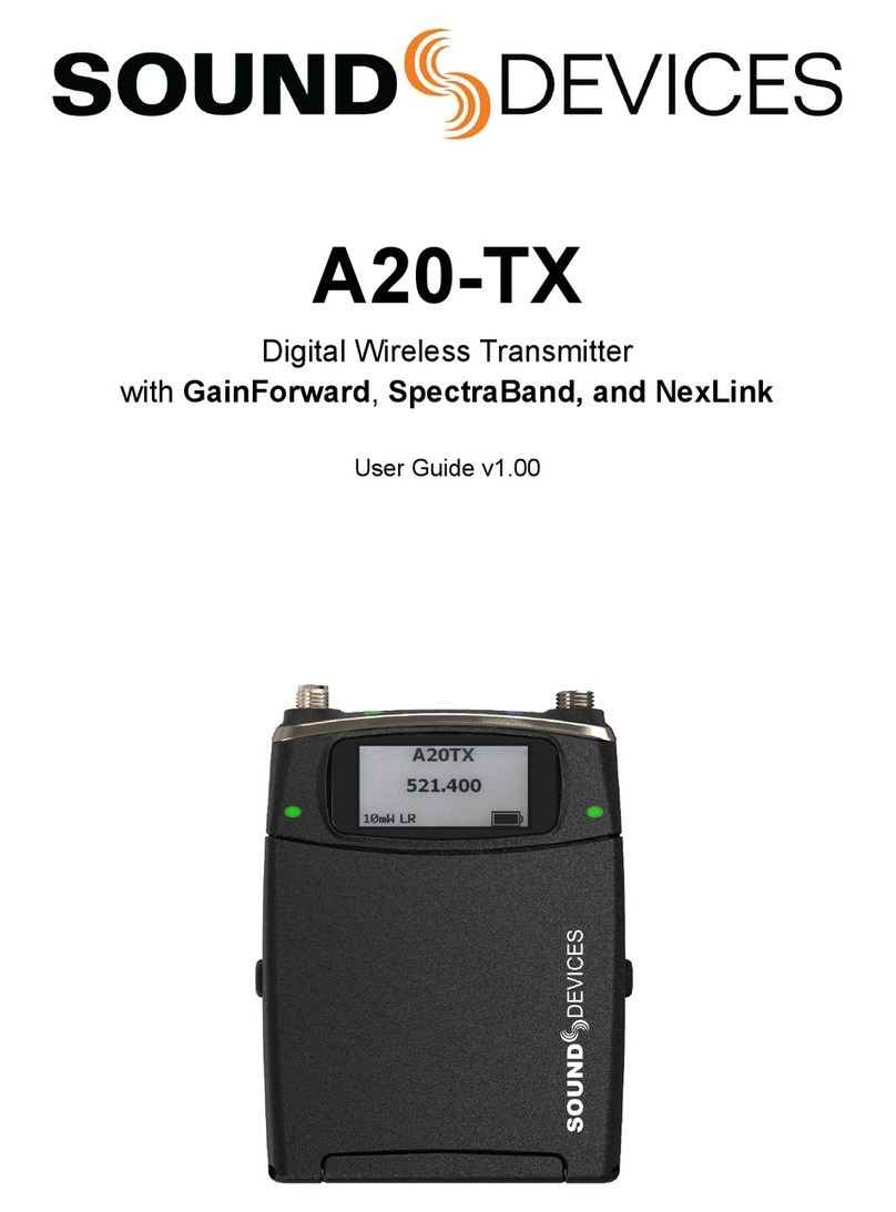
Sound Devices A20-Mini User manual

A20-MINI
Compact Transmitter
User Guide

A20-MINI User Guide 2
Table of Contents
3 Welcome to the A20-MINI
4 Panel Views
6 Power
7 Introduction to SD-Remote
8 SD-Remote Overview
10 Device List
10 Pairing an A20-MINI with SD-Remote
10 Adding an A20-MINI to the TX List
11 TX View
11 TX List
12 Controlling an A20-MINI from SD-Remote
12 Turning A20-MINI On from SD-Remote
12 Naming the A20-MINI
13 Setting Frequency
13 Setting RF Power
13 Tuning A20-MINI and the Audio Ltd A10-RX
13 Adjusting Audio of the A20-MINI Signal
from the A10-RX
13 Recording WAV Files on A20-MINI
13 Recording with A20-MINI
Purchased in the U.S.A.
13 Jamming Timecode on A20-MINI
14 Files View
14 File Info View
14 Delete a File
15 Settings View
15 Privacy/Encryption
15 Stealth Mode
15 Auto Power On When Removed from the
XL-PowerStation
15 Auto Power with Lav Mic Connection
15 Formatting the Internal SSD
15 Location
15 Save User Settings
15 Load Settings
16 Regulatory
16 Update Firmware
16 DTMF Tones Mode
16 SD-Remote Version
16 A20-MINI Version
16 A20-MINI Serial Number
17 User Groups
17 Naming the User Group
17 Activate the User Group
17 New User Group
17 Save User Group
17 Open User Group
17 Share User Group
17 Adding and Naming User Group Frequencies
18 File Transfer to a Computer
19 Mic2Wav II
19 Installing Mic2Wav II
19 Importing A20-MINI
WAV Files into Mic2Wav II
19 RemovingWAVlesfromtheSourceWindow
19 Selecting Files to Process
19 Naming of Processed WAV Files
20 Creating Shorter WAV Files Based on
Timecode Range
20 Selecting Bit Depth of Processed WAV Files
20 Conforming A20-MINI WAV Files to
CSV Sound Reports
20 Adding Pre- and Post-Roll
20 Combining to Poly
20 Managing User Groups
20 Create a New User Group
20 Open an existing User Group
20 Edit the User Group
20 Add a User
20 Remove a User
20 Add a Group
20 Remove a Group
21 SaveUserGroupsasALUGles
21 Send User Group to TX/RX
21 Updating A20-MINI Firmware
22 XL-PowerStation
22 Charging Batteries with the XL-PowerStation
22 Bottom Panel
22 1/4”-20 Mounting Point
22 Powering the XL-PowerStation
23 Distributing Timecode to
A20-MINI Transmitters
23 Transferring A20-MINI
Files via XL-PowerStation
23 Updating A20-MINI
23 Firmware via XL-PowerStation
23 XL-PowerStationSpecications
24 A20-MINISpecications
25 Legal Notices
25 FCC Conformity
26 FCC Interference Statement
26 Industry Canada Conformity
26 WEEE Statement
26 Battery Advisory
26 A20-MINI User Guide Revision List

A20-MINI User Guide 3
• 470 MHz to 694 MHz UHF tuning range
simplifes purchasing and makes operation far
moreexiblethanbefore.RFpowercanbe
selected between 2, 10, 20, and 40 mW.
• Powers from AAA batteries (3) or Sony
NP-BX1 rechargeable Li-Ion battery. The
choice is yours, and no additional adapters or
expensive proprietary batteries needed.
• IP67waterproong.The A20-MINI is built
for the most extreme environments with its
extensive gasketing and solid construction.
• Zero-gain-controlarchitecture. Due to the extreme
dynamic range of the proprietary Sound Devices codec,
no gain setting is needed at the transmitter. System
gain is adjusted at the receiver, and worrying about the
gain setting at the transmitter is a thing of the past.
• Built-inLi-Ionbatterycharger. When using the
rechargeable Sony NP-BX1 battery, simply plug the
A20-MINI’s USB-C port and automatically charge the
battery. The A20-MINI senses when AAA batteries
are in the A20-MINI and disables the charger.
• Built-inBluetooth5.2LE allows for simple
Android/iOS control of parameters. The A20-MINI’s
built-in 2.4G antenna ensures excellent range.
A20-MINIcanbepoweredonandoentirely
via Bluetooth for extended battery life.
• Removable external UHF antenna w/ SMA
connector. An external antenna allows for the
mostecientoperationandgreatestrange.
• Optional XL-PowerStation allows for easy
batterycharging,letransfer,andtimecode
jamming of up to 8 A20-MINIs at a time.
• Built-in32-bitoataudiorecorder.32-bitoat
recording means never having to worry about setting
the transmitter gain, and never worrying about clipping
audio.Audiogainofthelecanbeadjustedupor
down in post.
Simultaneous Record and Transmit mode is not
available on A20-MINI units sold in the United States of
America.
• Built-in64GBSSD. No need to worry about SD card
management - audio recording is always available
withtheample-sizeddrive.Simplyooadlesviathe
high-speed USB port to a computer.
• Rock-solidtimecodewithsupercapacitorback-up.
The A20-MINI’s internal timecode generator can be
jammed to get 0.2ppm ultra-accurate timecode for
perfectly synchronized recordings. The supercapacitor
back-up allows for battery changes without having to
rejam timecode.
• Small, smooth, concealable, and
comfortabletowear.
• Included accessories:
• Antenna set (1 straight 470-548 MHz, 1 straight
548-638 MHz, 1 straight uncut, 3 antenna caps).
Welcome to the A20-MINI
The Sound Devices A20-MINI wireless microphone transmitter builds upon the heritage and technology of the phenomenal-sounding
AudioLtdA10-TXtransmitter.TheA20-MINIoersthefollowingfeatures:

A20-MINI User Guide 4
Panel Views
Antenna
Connector
Power
LED
Top Bottom
USB-C
Port
Charge/Pair/
Record LED
Charge &
Timecode LED
Lavalier Microphone
Input
Audio/LTC
LED
FRONT RIGHT
LEFT
TOP
BOTTOM
BACK
Dimensions - mm
SCALE 1 : 1
Dimensions - in
SCALE 1 : 1
.000
2.918
3.140
.717 1.882
.00
74.11
79.76
47.80
18.20
FRONT RIGHT
LEFT
TOP
BOTTOM
BACK
Dimensions - mm
SCALE 1 : 1
Dimensions - in
SCALE 1 : 1
.000
2.918
3.140
.717 1.882
.00
74.11
79.76
47.80
18.20
PowerLED
Indicates the state of battery life.
• Green = Good
• Yellow = Marginal
• Red = Low
• Blue=Servicemodeforloadingrmware
Antenna Connector
SMAconnector.Attachantennawithalengthspecictothe
frequency in use. Using the wrong length of antenna reduces RF
range.
USB-C Port
Multifunction port used for:
• Charging internal Sony NP-BX1
rechargeable battery (not included)
• Timecode input and output
• Transferringlestoandfromacomputer
• Updatingrmware
Connect Linear Timecode (LTC) devices to the A20-MINI
USB-C port using the optional Sound Devices XL-TCU-LEMO
or XL-TCU-BNC cables. Upon connecting LTC, the transmitter
automatically jams timecode values and sets the frame rate to
the incoming source. Successful jam is indicated by the Audio/
LTCLEDashingblueonthe00frame.TheSoundDevicesXL-
TCU-LEMO provides access to the A20-MINI timecode output if
you want to verify correct LTC jam.
Charge/Pairing/RecordLED
Indicates charging, Bluetooth pairing, and recording.
• Solid Yellow = Charging
• Solid Green = Charging complete
• O=Nocharging
• Rapid Flashing Blue = Bluetooth Pairing
mode or setting changed via DTMF tones.
• Solid Red = Recording
• Flashing Red = Recording stopped due
to full media or recording error.
Lavalier Microphone Input
3-Pin LEMO connector for connecting a lavalier microphone.
Canbesettopowertransmitteronandovialavmicconnec-
tion and disconnection.
Audio/LTCLED
Audio/LTC LED indicates audio activity and timecode status.
• Green (variable intensity) = Audio activity
from lavalier microphone
• Red = Microphone clipping
• Flashing Blue = Timecode 00 frame (only when
unitisoorwhenjammingtimecode)
• Solid Blue = Microphone is muted
Note: Due to the extremely high dynamic range of the micro-
phone input, under normal use the audio LED should never light
up red. If it does, this is an indicator that the microphone itself
(not the mic preamp) is clipping and the audio level should be
attenuated acoustically by moving the mic capsule or using a
lower sensitivity microphone.
Charge&TimecodeLED
Positioned on the bottom of the A20-MINI to make it easily
visible when slotted into the optional XL-PowerStation. LED
indicates charging status, timecode sync, Bluetooth pairing, and
recording status.
• Solid Yellow = Charging
• Solid Green = Charging complete
• O=Notcharging
• Flashing Blue = Timecode 00 frame (only when
unitisoorwhenjammingtimecode)
• Rapid Flashing Blue = Bluetooth Pairing mode
• Solid Red = Recording
• Flashing Red = Recording stopped due
to full media or recording error

A20-MINI User Guide 5
Panel Views
FRONT RIGHT
LEFT
TOP
BOTTOM
BACK
Dimensions - mm
SCALE 1 : 1
Dimensions - in
SCALE 1 : 1
.000
2.918
3.140
.717 1.882
.00
74.11
79.76
47.80
18.20
FRONT RIGHT
LEFT
TOP
BOTTOM
BACK
Dimensions - mm
SCALE 1 : 1
Dimensions - in
SCALE 1 : 1
.000
2.918
3.140
.717 1.882
.00
74.11
79.76
47.80
18.20
FRONT RIGHT
LEFT
TOP
BOTTOM
BACK
Dimensions - mm
SCALE 1 : 1
Dimensions - in
SCALE 1 : 1
.000
2.918
3.140
.717 1.882
.00
74.11
79.76
47.80
18.20
FRONT RIGHT
LEFT
TOP
BOTTOM
BACK
Dimensions - mm
SCALE 1 : 1
Dimensions - in
SCALE 1 : 1
.000
2.918
3.140
.717 1.882
.00
74.11
79.76
47.80
18.20
3 AAA Batteries
SCALE 1 : 1
No Batteries
SCALE 1 : 1 Sony NP-BX1 Battery
SCALE 1 : 1
Front Front
Front
(Door Open)
RightLeft
Battery
Door
ButtonBattery
Compartment
Battery Door
Access to the battery compartment and button.
Battery Compartment
Accepts either 3x AAA Lithium batteries, or one rechargeable
Sony NP-BX1 Li-Ion battery. Sound Devices recommends using
Energizer Ultimate AAA batteries for best performance. Alkaline
and NiMH are not recommended because of compromised run
times.
Button
ThisbuttonisusedtopowertheA20-MINIonoroandenter
Bluetooth Pairing mode.
• Power On = Press and release button.
• PowerO=Pressandholdbuttonfor1second.
• PairingMode=WhileA20-MINIiso,pressandhold
button for 5 seconds. The Pairing LED on the bottom and
toppanelashesbluerapidlywhileinPairingmode.

A20-MINI User Guide 6
Power
The A20-MINI powers via 3x AAA Energizer Ultimate or one
Sony NP-BX1 Li-Ion battery.
Powering from AAA or Sony NP-BX1 Li-Ion
To power the A20-MINI using AAA batteries or Sony NP-BX1
Li-Ion:
1. Open the A20-MINI battery door.
2. Insert three AAA batteries or one Sony NP-BX1
Li-Ion into the battery compartment taking care to
place the batteries in the correct polar orientation.
3. Press and release the button to
power the A20-MINI on.
4. Close the A20-MINI battery door.
5. TopowertheA20-MINIo,pressandhold
the button for one second. The Power LED
ashesrapidlywhiletheA20-MINIpowerso.
ThePowerLEDisowhentheunitiso.
USB-C
USB-C can be used to charge Sony NP-BX1 batteries inserted
in the A20-MINI. Sony NP-BX1 battery charging only occurs if
the USB-C host port provides at least 1.5 A. The A20-MINI does
not charge AAA batteries.
To charge the Sony NP-BX1 from USB-C:
1. Open the battery door and insert a Sony
NP-BX1 into the battery compartment.
2. Connect a USB-C host providing at least
1.5 A to the A20-MINI USB-C port.
3. The Charge/Pair/Rec LED glows solid yellow
while the battery is charging. The Charge LED
turns solid green when charging is complete.
XL-PowerStation
The XL-PowerStation is an optional accessory for the A20-MINI.
An A20-MINI using a Sony NP-BX1 battery can be inserted into
a charging bay of the XL-PowerStation to charge the battery.
See XL-PowerStation for more details.
AutoPowerOnandOwithXL-PowerStation
TheA20-MINIautomaticallypowersowheninsertedintoa
charging bay of the XL-PowerStation. To save time from having
to manually power on the A20-MINI, use the Power On When
Removed from the XL-PowerStation feature. When on, removing
an A20-MINI from the XL-PowerStation immediately powers
thetransmitteron.Thisfeaturecanbeturnedonorointhe
SD-Remote application. See SD-Remote for more details.
Auto Power with Lav Mic Connection
The A20-MINI optionally auto-detects the lav mic connection
andpowersonandoaccordingly.WhenAutoPowerwithLav
Mic Connection is on, connecting a lavalier microphone to the
A20-MINI automatically powers the transmitter on. Removing
theLEMOconnectionautomaticallypowerstheA20-MINIo.
ThisfeaturecanbeturnedonorointheSD-Remoteapplica-
tion. See SD-Remote for more details.
ExpectedBatteryLife
The table below shows expected battery rundown times for
Sony NP-BX1 Li-Ion and three Energizer Ultimate AAA batter-
ies based on RF Power setting and whether the A20-MINI is
recording.
RF Power & Re-
cord
Sony NP-BX1 3x AAA
(EnergizerUltimate)
RFPowerO --:-- --:--
2 mW --:-- --:--
10 mW --:-- --:--
20 mW --:-- --:--
40 mW --:-- --:--
RFO,Recording --:-- --:--
2 mW, Recording --:-- --:--
10 mW, Recording --:-- --:--
20 mW, Recording --:-- --:--
40 mW, Recording --:-- --:--

A20-MINI User Guide 7
Introduction to SD-Remote
SD-Remote is a mobile device application for Android/iOS
phones and tablets designed to pair with the A20-MINI. To keep
the size, weight, and power consumption of the A20-MINI to a
minimum, all settings of parameters and functions are per-
formed using the SD-Remote mobile device application.
A mobile device connects via Bluetooth LE to the A20-MINI.
SD-RemoteoerscontrolanddisplayofallA20-MINIparame-
ters. This includes the following:
1. PoweronandotheA20-MINI
2. Monitor battery status
3. Frequency and RF setup
4. Monitor audio signal presence
5. Microphone mute
6. Transport controls (Record, Stop)
7. Timecode display
8. SSD formatting and monitoring of remaining space
9. System settings (stealth mode, charging
options, User Groups and more)
10. Firmware updating
11. Control of select A20-MINI settings using DTMF
tones.
This guide describes the “Wireless” tab and functionality of
SD-Remote. The Recorder tab is described in the Sound Devic-
es 8-Series guides.
Download and install the SD-Remote app from the Google Play
Store or Apple App Store.
SD-Remote has the following minimum operating requirements:
Android tablets and phones running Android 8+, or
iPad and iOS devices running iOS 13+.
The mobile device’s location is used to determine available
features and TV channel mapping of the A20-MINI. The mobile
device’s system date and time are used in the metadata of
recordedlesandwhenusingtime-of-daytimecode.

A20-MINI User Guide 8
SD-Remote Overview
Phone Tablet
Navigation
Bar
Navigation
Bar
Recorder/
Wireless Tab
Recorder/Wireless
Tab
TX
List TX
View
TX
View
Files
View
Settings
View
TX
List
Active
Transmitter
Active
Transmitter
Recorder and Wireless Tabs
Active tab is highlighted in blue. The Wireless tab is shown as
the active tab in the example image and is described in this
guide.
TX List
Scroll to see all available transmitters in the TX List. Touch a
transmitter to select it to be the active transmitter for the TX
View. Transmitters are added and removed from the TX List from
the Device List. See TX List for more details.
Active Transmitter
The triangular indent in the TX List indicates the active transmit-
ter shown in the TX View.
TX View
Displays the active transmitter’s audio activity, battery life, and
timecode values. Allows control of transmitter’s power, RF set-
up, record and stop. See TX View for more details.
Files View (Tablet)
The A20-MINI Files View displays remaining time and space left
ontheinternalSSD.Displaysascrollablelistofrecordedles.
Touchalenameformoreoptions.FilesViewisavailableonthe
phone by touching the SSD icon in the TX View. See File View
for more details.
Settings View (Tablet)
Allows control of various A20-MINI settings. Displays the ver-
sionnumberofSD-Remoteandthermwareversionandserial
number of the active A20-MINI. Settings View is available on a
phone by touching the Settings (gear) icon in the Navigation Bar.
See Settings View for more details.

A20-MINI User Guide 9
Navigation Bar
Icons on the navigation bar indicate the various views of the
SD-Remote Wireless Tab. Touch an icon to display the corre-
sponding view.
Icon Description
Device List
The Device List is where you pair A20-
MINI over Bluetooth to SD-Remote. See
Device List for more details.
TX View
Displays the active transmitter’s audio
activity, battery life, and timecode values.
Allows control of transmitter’s power, RF
setup, record and stop. See TX View for
more details.
User Groups
The User Groups View is where you can
name frequencies with intuitive names
and limit the frequencies available. See
User Groups for more details.
Settings View (Phone)
Allows control of various A20-MINI
settings. Displays the version number
ofSD-Remoteandthermwareversion
and serial number of the active A20-MINI.
Settings View is available on a phone by
touching the Settings (gear) icon in the
Navigation Bar. The Settings View is visi-
ble in the TX View on tablets and does not
have a Navigation Bar icon. See Settings
View for more details.

A20-MINI User Guide 10
Device List
Pair A20-MINI over Bluetooth to SD-Remote on the Device List.
The Device List displays all transmitters within range that are in
Pairing mode and any A20-MINI that has been previously paired
to the mobile device.
Icon Status
No devices connected.
Establishing connection.
Active connection.
Pairing an A20-MINI with SD-Remote
WiththeA20-MINIo,openthebatterydoorthenpressand
holdthemulti-functionbuttonforveseconds.TheBluetooth
LEDashesbluerapidlywhileinPairingmode.
From the SD-Remote Device List, touch the + button to pair an
A20-MINI to the mobile device. To remove an A20-MINI from the
Device List, touch the X button. Once removed, you will need to
repeat the pairing process again to re-add the transmitter to the
Device List.
Adding A20-MINIs to the TX View - TX List
From the SD-Remote - Wireless - Device List, add or remove a
transmitter to the TX List using the TX List button.

A20-MINI User Guide 11
TX View
The TX View contains the TX List and a view of the active trans-
mitter’s audio activity, battery life, and timecode values, and
allows control of transmitter’s power, RF setup, record and stop.
Touch the TX icon in the Navigation Bar to display the TX View.
TX List
The TX List is displayed on the left-hand side of the TX View.
This scrollable list displays all transmitters added to the TX List
and a high-level view of a transmitter’s status. This includes
the transmitter’s name, set frequency, and the status of battery
level/charging, power, record, and RF transmission.
Icon Description
A20-MINI Status Indicator
The A20-MINI is powered off.
A20-MINI Status Indicator
The A20-MINI is not recording or transmitting.
A20-MINI Status Indicator
The A20-MINI is transmitting but not recording.
A20-MINI Status Indicator
The A20-MINI is recording but not trans-
mitting.
A20-MINI Status Indicator
The A20-MINI is transmitting and recording.
Battery Level Indicator
Displays the level of the battery from no bars (no
battery) to four bars (full charge).
Battery Charge Indicator
Displays the charging status of the battery.
ChargingErrorIndicator
Displays when the battery is not able to charge.
Possible causes for charging errors:
• USB is connected but AAA
batteries are inserted.
• USB is connected but no battery is present.
• USB is connected but is not
providing 1.5 A or more.
Identify Unit
Touch the Identify Unit icon to put the A20-MINI
into identify mode. The LEDs on the A20-MINI
ashfor30secondsmakingiteasytolocatethe
A20-MINI you want to control.
A20-MINI Name
Displays the name of the A20-MINI.
A20-MINI Frequency
Displays the set frequency of the A20-MINI.

A20-MINI User Guide 12
Active A20-MINI in the TX View
The active A20-MINI in the TX View is indicated by the indent on
the right-hand side of the TX List. Touch any transmitter in the
TX List to make it the active transmitter.
Audio Signal Presence/Mic Mute
The Mic icon varies in intensity when audio
signal is present. Touch the Mic icon to mute
the microphone. To prevent accidental muting,
aconrmationdialogpopupappearsaskingto
conrmthechange.Whenmuted,noaudiois
present in the recordings or transmitted.
Transmitter Power
Touch the Power icon to turn the A20-MINI on
oro.Theiconwillbegraywhenthetransmit-
terisoandwhitewhenthetransmitterison.
Record
Touch the Record icon to start a recording on
the A20-MINI. The icon is red while recording.
Stop
Touch the Stop icon to stop a recording on the
A20-MINI. The icon is yellow while recording is
stopped.
Files View
On a phone, touch the SSD icon to see the
A20-MINI Files View. See Files View for more
information.
License Required
Some frequencies may require a license to
operate on in your area. The LIC icon appears
if the set frequency requires a license for your
location.
Controlling A20-MINI from SD-Remote
While in the TX View, touch the A20-MINI from the TX List you
wish to control or view in more depth. The selected transmitter
is displayed to the immediate right of the TX List.
From the TX View you can control parameters of the A20-MINI
and get a detailed view of audio signal presence, timecode, and
more.
Naming the A20-MINI
WhileintheTXView,touchthenameeldandusethepopup
QWERTY keyboard to rename the transmitter. You are allowed
up to twelve alpha-numeric characters. The transmitter’s name
is the serial number of the unit by default. Names are tied to
User Group frequency when using User Groups. See User
Groups for more detail.

A20-MINI User Guide 13
Setting Frequency
The A20-MINI transmits on frequencies ranging from 470
MHz–694 MHz. The frequencies available are determined by
your geographic location. See https://www.sounddevices.com
for further information regarding the available frequencies and
TV channel mapping in your area.
Pre-selected frequencies are available based on TV channels
and sub channels. Three sets of frequencies are available
based on either 6, 7, or 8 MHz channel bandwidth. The channel
bandwidth is based on the geographic region where the unit is
operating.
• 6 MHz per TV channel:
North America, South Korea, Philippines,
China, Taiwan, Japan
• 7 MHz per TV channel:
Australia and New Zealand
• 8 MHz per TV channel:
UK and Western Europe , Greenland, Asia, Africa
Touch the frequency display to change the frequency manu-
ally with numeric values in 25 kHz increments or touch the TV
channel to select from available TV channels and sub-channels.
When User Groups are active, the method of selecting frequen-
cy changes. See User Groups for more details.
Setting RF Power
RF power is the strength of the transmitting signal. The A20-
MINIoersthefollowingRFpowersettings.
• O-A20-MINIisonbutisnottransmitting.
• 2 mW
• 10 mW
• 20 mW
• 40 mW
RF power settings are based on your location as some legal
restrictions may apply. Touch “RF Power” and select from the
drop-down list.
Tuning A20-MINI and the Audio Ltd A10-RX
Signal transmitted by the A20-MINI transmitters are received
by the Audio Ltd A10-RX. Enter the frequency of the transmitter
you wish to receive on the A10-RX either by manually tuning the
number or using the TV channel and sub channel. Be sure to
properly set the A10-RX to the proper TV channel map for your
area when using the TV channel method. See Frequency Tables
for more information.
The A20-MINI uses a very advanced codec and RF transmission
scheme such that the audio gain, low-cut, and limiter are adjust-
ed at the receiver instead of transmitter.
Adjusting Audio of the A20-MINI Signal from the A10-RX
From the A10-RX, press the channel’s arrow button twice to
view the status of the tuned A20-MINI. Press the middle button
to enter the menu. From the menu select to adjust gain, limiter,
or low cut of the incoming A20-MINI transmitted signal. Gain is
adjustablefrom0to40dB.Limitercanbeturnedonoro.Low
cutcanbesettoO,40Hz,60Hz,80Hz,100Hz,or200Hz.
See the A10-RX User Guide for more details.
Recording WAV Files
TheA20-MINIrecords32-bitoatRF64WAVlesat48kHz
samplingrates.Recordingofaudiolesisautomaticallydonein
32-bitoatsothatsettinggaintoohighorlowisneveraprob-
lem.Learnmoreabout32-bitoatat:
https://www.sounddevices.com/category/support/tech-notes/
Recordings are started and stopped using the record and stop
buttons in the TX View.
ThelenameformatisTXName-YYMMDDHHMMSS.WAV.For
example, the TX name has been changed to “Barney” and a
recording is created on June 10, 2021 at 9:30 in the morning,
theresultingleisnamedBarney-210610093000.WAV.Allles
are recorded at root of the internal SSD (no folders).
RecordingwithA20-MINIPurchasedintheU.S.A.
Simultaneous Record and Transmit mode is not available on
A20-MINI units sold in the United States of America.
Record features of A20-MINI transmitters purchased in the U.S.A. are
only available when RF Power is set to Off.
Jamming Timecode
The A20-MINI jams timecode from an external LTC source via
USB. The timecode value and frame rate are taken from incom-
ing LTC source. If timecode has not been jammed, the A20-MINI
stampslesusing the time of day, derived from the mobile
device running SD-Remote.
Timecode values are held for up to four hours after power
down, and for one hour after the battery has been removed.
This allows for time to swap batteries without having to re-jam
timecode.
To jam timecode, connect a valid LTC source using one of the
optional accessories Sound Devices XL-TCU-LEMO or XL-TCU-
BNC to the USB-C port. Timecode is automatically jammed
once a valid LTC source is connected.
Afterasuccessfultimecodejam,theAudio/LTCLEDashes
blue on the 00 frame crossing. Timecode is output from the
USB-C using the Sound Devices XL-TCU-LEMO so that you can
verify the A20-MINI timecode is in sync with the LTC source.
The A20-MINI can also jam timecode while connected to the
optional XL-PowerStation via USB-C. See XL-PowerStation for
more details.

A20-MINI User Guide 14
Files View
The A20-MINI Files View is displayed in the center of the TX
View on a tablet and is accessed by touching the SSD icon on
a phone. Remaining space, remaining record time, and a list
ofrecordedlesontheSSDaredisplayed.Touchaletoview
moreinformationaboutthele.
Icon Description
File Info View
TheFileInfoViewdisplaysthelename,
creation time and date, start timecode
stamp,durationofrecording,lesize,
and provides the option to delete the le.
Delete a File
From the File Info View delete a
lebytouchingtheTrashiconand
conrmingthedialogpopup.

A20-MINI User Guide 15
Settings View
The Settings View is displayed on the far right-hand side of the
tablet view. On a phone touch the Settings (gear) icon in the
Navigation Bar to display the Settings View.
The Settings View allows control of less often changed param-
eters of the A20-MINI. It displays the version and serial number
of the active A20-MINI and the SD-Remote version number.
Privacy/Encryption
When Privacy is on, the A20-MINI automatically generates and
displays a four digit code. When on, audio is encrypted and the
four digit code needs to be set on receiver to get audio.
Stealth Mode
When you need the A20-MINI to be discreet turn on Stealth
mode.InStealthmode,allA20-MINILEDsareturnedo.
Auto Power On When Removed from the XL-PowerStation
TheA20-MINIautomaticallypowersowheninsertedintoa
charging bay of the XL-PowerStation. To save time from having
to manually power on the A20-MINI, use the Power On When
Removed from the XL-PowerStation feature. When on, removing
the A20-MINI from the XL-PowerStation powers the transmitter
on.Thisfeaturecanbeturnedonoro.SeeXL-PowerStation
for more details.
Auto Power with Lav Mic Connection
The A20-MINI optionally auto-detects the presence of the lava-
liermicrophoneconnectionandpowersonandoaccordingly.
When Auto Power with Lav Mic Connection is on, connecting
a lavalier microphone to the A20-MINI automatically powers on
the transmitter. Removing the lavalier mic connection automati-
callypowerstheA20-MINIo.Thisfeaturecanbeturnedonor
o.
Formatting the Internal SSD
FormattingtheA20-MINISSDdeletesallrecordedles.Itis
goodpracticetobackuplesbycopyingthemtoacomputer
then formatting the SSD periodically.
In the event you need to run a low-level format from a com-
puter, you still need to format the SSD by the A20-MINI before
recordingles.
Location
Location is automatically set if GPS or Location Services are
available on the mobile device. Use this menu to manually set
your location when these services are unavailable.
Save User Settings
Saves the current settings of the active A20-MINI to the internal
SSDorash.Settingslescanbeloadedatalatertimeor
transferred to another A20-MINI via a computer.
Load Settings
Loadsfactorydefaultsettingsorusersetuplesstoredonthe
activeA20-MINI’sinternalSSDorash.

A20-MINI User Guide 16
Regulatory
Displays compliance documentation for local government
requirements.
Update Firmware
SearchestheSoundDeviceswebsiteforthelatestrmware
PRGandloadsthenewrmwareontheA20-MINI.
DTMF Tones Mode
DTMF Tones mode is useful in the very unlikely event that Blue-
tooth cannot connect and you still need to change parameters
of the A20-MINI. Using DTMF tones you can turn the transmitter
onoro,changethefrequency,startorstoprecordings,and
mute or unmute the microphone.
Touch the frequency display to change the frequency manual-
ly with numeric values or touch the TV channel to select from
available TV channels and sub-channels. Touch anyone of the
radio buttons to play the DTMF tone out of the mobile device’s
speakers. Adjust the volume using the fader.
Position the mobile device close to the lav mic attached to the
A20-MINI. The A20-MINI changes settings based on the DTMF
toneplaying.TheA20-MINIPairingLEDashesbluefor5sec-
onds when a setting has been changed via a DTMF tone.
Deselect all radio buttons to stop DTMF tones from playing. Be
aware of your volume levels and your relation to other trans-
mitters to avoid accidental setting changes. Touch any of the
Navigation Bar icons to exit DTMF mode.
SD-Remote Version
Displays the current version of SD-Remote.
A20-MINI Version
DisplaysthecurrentrmwareversionofA20-MINI.
A20-MINI Serial Number
Displays the A20-MINI serial number.

A20-MINI User Guide 17
User Groups
The User Groups feature allows for easy, intuitive naming of
specicfrequenciesforeachA20-MINIorAudioLtdA10-TX
transmitters used on set, and grouped together for faster tuning.
The operator of an A10-RX receiver may then easily switch
between transmitters by choosing alphanumeric names, such
as “Jack” and “Diane”, instead of having to remember and man-
uallytunetodierent,specicnumericalfrequencies.
For instance, a producer or director may want to monitor several
dierentactors’wirelesstransmitters.Ratherthanhavingto
keep a list of all of their frequencies, each transmitter may be
pre-assigned a frequency and given an actor’s name. Then only
those pre-assigned frequencies that have been named will be
available as possible options for tuning.
User Groups are created in the SD-Remote - Wireless Tab -
User Groups View. User Groups can also be created using the
Mic2Wav II Windows and Mac OS application. See Mic2Wav II
for more details.
Naming the User Group
TouchthenameeldtorenamethecurrentUserGroup.
Activate the User Group
When Activate User Group is on, the User Group is applied to
all A20-MINI transmitters within Bluetooth range that appear in
the TX List. This limits the frequencies available to only those
denedbytheUserGroupandliststhembytheirfriendlyname.
Unlike the A20-MINI, the Audio Ltd A10-TX and A10-RX do not
automatically update when Activate User Groups is on. ALUG
lesneedtobemanuallyloadedonthesedevices.Seethe
Audio Ltd A10-TX and A10-RX guides for details.
New
Creates a new User Group clearing existing entries.
Save
SavesthecurrentUserGroupasanALUGletothemobile
device.SavedALUGlescanberecalledlater,transferredtoan
A10-TX microSD card, or loaded onto an A10-RX via Mic2Wav
2.
Open
OpensstoredALUGlesonthemobiledeviceandloadsthem
in SD-Remote.
Share
SharestheactiveUserGroupasanALUGleviaemailorthird
partylesharingapplications.
Adding and Naming User Group Frequencies
• Touch + to add an entry to the User Group.
• Touch X to delete an entry from the User Group.
• Touchthenameeldtoeditthefrequency’sname.
• Touchthefrequencyeldtoassignafrequency.
• Touchtheserialnumbereldtoenteraspecic
A20-MINI or A10-TX serial number. This auto-deploys
the frequency to the A20-MINI or A10-TX without having
to change the frequency selection on each transmitter.

A20-MINI User Guide 18
File Transfer to a Computer
The A20-MINI connects via USB-C to a computer as a mass
storagedevice.CopyWAVandUserSetuplesfromtheA20-
MINItothecomputer.CopyPRGandUserSetuplesfromthe
computer to the A20-MINI.
Files copied to the A20-MINI should be copied without folders
totherootoftheA20-MINI’sSSD.Whenletransferiscom-
plete, eject the drive from the operating system and disconnect
USB.
Up to eight A20-MINI transmitters can be connected to a com-
puterforletransferusingtheoptionalXL-PowerStation.See
XL-PowerStation for more details.

A20-MINI User Guide 19
Mic2Wav II
SoundDevicesMic2WavIIisacompanionapplicationforMacandWindows.Thisapplicationcanbeusedtoconformthe32-bitoat
WAVlesrecordedbytheA20-MINItransmitterstoaCSVSoundReport,combinemonophoniclesfrommultipleA20-MINItransmit-
tersintoasinglepolyphonicle,updateA20-MINIrmware,createandmanageUserGroups,andmore.
Mic2WavIIisalsoacompanionapplicationfortheAudioLtdA10-TXandA10-RX.Fordetailsspecictothoseproducts,pleaserefer
to the respective user guide.
Installing Mic2Wav II
Download the Mic2Wav II Installer for Mac or Windows from
https://www.sounddevices.com. Open the installer and install
the application by following the on-screen instructions.
Minimum operating requirements:
• macOS 10.11+, 64-bit
• Windows 7+, 64-bit
Importing A20-MINI WAV Files into Mic2Wav II
Mic2WAVIIwillimportmonophonicWAVlesrecordedbythe
A20-MINIorMIClesrecordedbytheAudioLtdA10-TX.There
arethreemethodsforimportinglesintoMic2WavII.
1. Drag-and-dropWAVlesintotheSourcewindow.
2. NavigateFile>AddandselectWAVle(s)forimport.
3. On the bottom left of the Source window, click + on
MacorAddonWindows,thenselectle(s)forimport.
The Source window displays the following information for all
importedles.
• Filename
• Transmitter name
• Dateandtimeoflecreation
• Start timecode
• End timecode
• Length of recording
RemovingWAVlesfromtheSourceWindow
TherearetwomethodsforremovingWAVlesfromtheSource
window.
1. HighlighttheWAVle(s)toberemoved
from the Source window, then click - on
Mac or Remove on Windows.
2. HighlighttheWAVle(s)toberemovedfromthe
Source window, then navigate File > Remove.
Selecting Files to Process
Highlightthele(s)youwanttoprocessfromtheSourcewin-
dow.Multiplelescanbeselectedusingkeyboardmodiers,
AppleandShiftonMac,CtrlandShiftonWindows.Ifnoles
areselected,processingisappliedtoalllesintheSource
window.
Naming of Processed WAV Files
ProcessedWAVleswillbenamedaccordingtotheFilename
selection.
• Match Sourceusesthesourcele’s
nameintheprocessedWAVle.
• Replace withallowstheprocessedleto
be named based on the custom entry.
• Conform to CSV uses the take information from a CSV
SoundReporttodeterminetheprocessedlenames.See
Conforming A20-MINI WAV Files to CSV sound reports.

A20-MINI User Guide 20
Creating Shorter WAV Files Based on Timecode Range
WhenashorterWAVleisneededthantheoriginalrecording,
you can use the Timecode Range feature to create a shorter
WAVle.Thelengthandcontentoftheprocessedleisbased
on the entered timecode start and stop times.
1. Highlightthesourcele(s)fromtheSourcewindow.
2. Select the Timecode Range check box.
3. Enter valid timecode start and end times. The
valuesmustfallwithintherangeofthesourcele.
4. Select Process.
Selecting Bit Depth of Processed WAV Files
TheA20-MINIrecords32-bitoatWAVles.TokeeptheWAV
lesin32-bitoat,select32Float.Ifyouwanttoconvertthe
32-bitWAVlesto24-bitinteger,select24.
24-bitlesthatcontainaudiothatexceeds0dBFSwillbenor-
malized to -0.1 dBFS to avoid clipping.
Conforming A20-MINI WAV Files to CSV Sound Reports
CSVsoundreportlesgeneratedbySoundDevicesrecorders
can be used to extract only relevant audio from the A20-MINI
WAVorA10-TXMICles.AudioisextractedandanewWAVle
is created based on the timecode in/out values of takes listed
within the CSV.
TheprocessedWAVlenamesandembeddedmetadataare
changedtomatchthelenamesandmetadataofthecorre-
sponding takes in the CSV sound report.
• Adding Pre- and Post-Roll toconformedlescanbenet
post production with access to audio just prior to and
following head and tail slates. To add pre- and post-roll to
conformedWAVles,selectthePre/PostRollcheckbox
and enter a value from 0 to 10 seconds in 1 second steps.
• Combining to PolycreatesasinglepolyphonicWAVle
containing audio tracks from each relevant transmitter
for takes of the CSV sound report. Select the Combine to
Polycheckboxtocreateapolyphonicleforeachtake,
leaveuncheckedformonophoniclesforeachtransmitter.
Managing User Groups
User Groups are fully described in the SD-Remote User Groups
section. Mic2Wav II allows the creation and editing of User
Groups,importingUserGroup(ALUG)les,andsendingALUG
lestoA20-MINItransmittersandAudioLtdA10-RXreceivers
connected to the computer via USB or the XL-PowerStation.
See the Audio Ltd A10-TX and A10-RX User Guides for more
information regarding User Group setup of these products.
• Create a New User Group by navigating on a Mac to
User Groups > New and on Windows to Files > User
Groups>Createanewle.
Enter the name of the User Group. Names should be
limited to 12 alphanumeric characters without spaces.
Underscores and dashes are permitted but no other
special characters can be used. Red text indicates the
entry is invalid.
Select the band you want to use. This will restrict
frequencies to the selected band. Note the A20-MINI
frequency range covers all available bands, the Audio Ltd
A10-TX frequency range is limited by model (A-D). Click
OK to create the User Group.
• Open an existing User Group by navigating on a Mac
to User Groups > Open and on Windows to Files > User
Groups>Openanexistingle.SearchtheBrowseror
FinderfortheALUGleyouwanttoOpen.ThenclickOK.
• EdittheUserGroup.ClickinU1(User1)nameeld
to name the User. Names should be limited to 12
alphanumeric characters without spaces. Underscores
and dashes are permitted but no other special characters
can be used. Red text indicates the entry is invalid.
Click the U1 Frequency to assign the user a frequency.
Frequency should be entered in XXX.XXX format and
fall within the range of the User Group band. Red text
indicates an invalid entry.
ClicktheU1TXSerialNumbereldtoentertheserial
number of the A20-MINI or A10-TX you want automatically
assigned to this user upon loading the User Group. This
eldisoptional.
• Add a User by clicking the + icon. Up to 32 users can be
entered for a single User Group.
• Remove a User by clicking the - icon.
• Add a Group by clicking Add Group. Up to 8 User Groups
canbesavedwithinasingleALUGle.
• Remove a Group by clicking Remove Group. This
removes the currently displayed Group. Remove Group is
not available and if there is only one group.
Other manuals for A20-Mini
2
Table of contents
Other Sound Devices Transmitter manuals
Popular Transmitter manuals by other brands
HK Instruments
HK Instruments DPT-Priima Series installation instructions
iSimple
iSimple JamKast ISFM31 instructions

Tele Radio
Tele Radio PN-T13-3 installation instructions
ANDERSON-NEGELE
ANDERSON-NEGELE MPP Installation and startup guide

Emerson
Emerson Rosemount Ultrasonic 3107 quick start guide
Linear
Linear Multi-Code MCS1082 installation instructions
