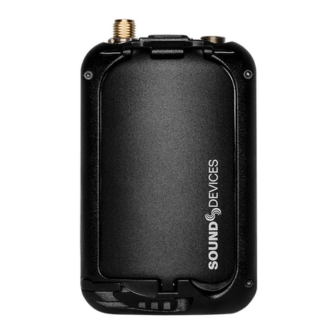
Sound Devices A20-Mini User manual

A20-Mini
Digital Wireless Transmitter
with GainForward and SpectraBand Technologies
User Guide v6.00

Table of Contents
Welcome to the A20-Mini 3
SpectraBand 4
Panel Views 4
Power 7
A20-Mini Holster 8
Introduction to A20-Remote 9
A20-Remote Overview 10
Manage Transmitters 13
Transmitter List 15
Transmitter View 19
Group Control 23
Group Setup 23
Group View 24
Connecting Lavalier Microphones to A20-Mini 28
Tuning A20-Mini and the Receiver 28
GainForward 28
Recording WAV Files 28
Jamming Timecode on A20-Mini 29
File Transfer to a Computer 29
Updating A20-Mini Firmware 30
SD-Utility 31
PowerStation-8M 34
PowerStation-8M Specifications 36
A20-Mini Specifications 37
Antenna Guide 39
Servicing the A20-Mini 40
Warranty 40
Included Accessories 40
Legal Notices 41
Declaration of Conformity 44
A20-Mini User Guide 2

Welcome to the A20-Mini
Sound Devices’ first miniature transmitter incorporates state-of-the-art features such as full remote control via the A20-Remote app,
long range modulation, GainForward Architecture, SpectraBand’s 470 MHz – 1525 MHz tuning range, internal 32-bit float recording,
and more. The A20-Mini is fully compatible with the A20-RX and the A10-RX.
● Worldwide tuning range of 470 MHz – 1525 MHz.
● Full remote control of the Mini via A20-Remote companion app.
● State-of-the-art 100% digital long-range modulation delivers the longest transmission distance of any system on the
market.
● GainForward Architecture: set the Mini’s gain levels via trim control (with an 8-Series) or at the A20-RX/A10-RX (other
mixers).
● Full 10 Hz – 20 kHz audio bandwidth; 100% digital RF modulation and transmission. Same excellent range and audio
quality as the A10-TX.
● Built-in 32-bit float, 48 kHz recorder with 64 GB storage for over 80 hours of record time.
● USB-C for file offload and optionally conform/convert with SD-Utility.
● Powering via Lithium AAA or NP-BX1 (Li-Ion) batteries with built-in charging for NP-BX1.
● Internal timecode generator with supercapacitor backup can be jammed via USB-C.
● Water-resistant with a rounded form factor.
Our friendly and knowledgeable support team, based in the USA and the UK, is here for all your questions and comments. Our job is
to make your job easier.
We are honored to be part of your kit.
Sincerely,
Sound Devices
A20-Mini User Guide 3

SpectraBand
The A20-Mini introduces SpectraBand, a technology that enables the A20-Mini to tune over a super wide range of 470-1525 MHz.
Tuning within this range varies by country. For instance:
In the USA, the available frequency ranges are:
●The entire UHF TV band (470-608 MHz)
●The 600 MHz guard band (614-616 MHz)
●The 600 MHz duplex gap (653-663 MHz)
●The 900 MHz ISM Band (902-928MHz)
●The 950 MHz STL Band (941.5-960 MHz)
●The 1.5 GHz AFTRCC band (1435-1525 MHz), with an appropriate license.
In the UK, the available frequency ranges are:
●The core UK UHF TV band (470-702 MHz)
●The 800 MHz duplex gap (823-832 MHz)
●The 800 MHz guard band (863-865 MHz)
●The DME bands (961-1015 MHz, 1045-1075 MHz, 1105-1154 MHz), with an appropriate license.
●The IMT band (1518-1525 MHz)
Please see https://www.sounddevices.com/frequency-tables/ for further detailed information on which frequency ranges are
available for each country.
Panel Views
Top and Bottom Panels
1: Battery Power LED
Indicates the state of battery life.
Green = Good
Orange = Marginal, about an hour of battery life remaining.
Red = Low, 15-20 minutes of battery life remaining.
Flashing Red = Critically low, RF, audio, and recording disabled.
Blue = Batteries inserted. Power LED is blue when batteries are inserted and goes off when the unit is ready to be powered on
by the red button or from the A20-Remote app.
2: Antenna Connector
SMA connector. Attach antenna with a length specific to the frequency in use. Using the wrong length of antenna reduces RF range.
See Antenna Guide for more information.
3: USB-C Port
Multifunction port used for:
A20-Mini User Guide 4

Powering A20-Mini
Charging internal Sony NP-BX1 rechargeable battery (not included)
Timecode input and output
Transferring files to and from a computer
4: Charge/Pairing/Record/Media/Timecode Jam LED
Indicates charging, Bluetooth pairing, recording, media activity, and timecode status.
Solid Orange = Charging
Solid Green = Charging complete
Off = No charging
Solid Red = Recording
Flashing Red = Recording stopped due to full media or recording error
Flickering Blue = Media activity
Flashing Blue = Timecode Jam in progress
Pulsing Blue = Timecode Output active
Rapid Flashing Blue = Bluetooth Pairing
5: Lavalier Microphone Input
3-Pin LEMO connector for connecting a lavalier microphone. Can be set to power transmitter on and off via lav mic connection and
disconnection.
6: Audio/Timecode LED
Audio/Timecode LED indicates audio activity and timecode status.
Green (variable intensity) = Audio activity from lavalier microphone
Red = Microphone clipping
Solid Blue = Microphone is muted
Pulsing Blue = Timecode 00 frame (only when unit is off)
Note: Due to the high dynamic range of the microphone input, under normal use the audio LED should never light up red. If it does,
this is an indicator that the microphone itself (not the mic preamp) is clipping and the audio level should be attenuated acoustically
by moving the mic capsule or using a lower sensitivity microphone.
7: Bottom Panel Charge/Pair/Record/Media/Timecode LED
LED indicates charging status, timecode sync, Bluetooth pairing, recording, and media activity. Positioned on the bottom of the
A20-Mini to make it easily visible when slotted into the optional PowerStation-8M.
Solid Orange = Charging
Solid Green = Charging complete
Off = Not charging
Solid Red = Recording
Flashing Red = Recording stopped due to full media or recording error
Flickering Blue = Media activity
Flashing Blue = Timecode Jamming
Pulsing Blue = Timecode 00 frame (when unit is off and jammed timecode is held or when Timecode Output is active following
a jam)
Rapid Flashing Blue = Bluetooth Pairing
Front, Front (Door Open), Left, Right and Back Panels
A20-Mini User Guide 5

1:Battery Door
Access to the battery compartment and red button.
2:Door Latch
Slide left to unlock the battery door.
3:Battery Compartment
Accepts either 3x AAA Lithium batteries or one rechargeable Sony NP-BX1 Li-Ion battery. Sound Devices recommends using
genuine Sony NP-BX1 or Energizer AAA Lithium primary batteries for best performance. Alkaline and NiMH are not recommended
because of compromised run times.
4:Red Button
This button is used to power the A20-Mini on or off and enter Bluetooth Pairing mode.
Power On = Press and release button.
Power Off = Press and hold button for 3 seconds.
Pairing Mode = While A20-Mini is off, press and hold button for 5 seconds. The Pairing LED on the bottom and top panel
flashes blue rapidly while in Pairing mode.
A20-Mini User Guide 6

Power
The A20-Mini powers via USB-C, 3x Energizer AAA Lithium primary batteries, or one Sony NP-BX1 Li-Ion battery.
Opening the Battery Door
To open the A20-Mini battery door:
1. Slide the door latch to the left to unlock the battery door.
2. Lift the battery door using the indented space on the bottom right-hand side of the battery door.
Closing the Battery Door
To close the A20-Mini battery door:
1. Slide and hold the door latch to the left.
2. Close the battery door.
3. Release the door latch to lock the battery door.
Powering from AAA or Sony NP-BX1 Li-Ion
To power the A20-Mini using AAA batteries or Sony NP-BX1 Li-Ion:
1. Open the A20-Mini battery door.
2. Insert three AAA batteries or one Sony NP-BX1 Li-Ion into the battery compartment, taking care to place the batteries in
the correct orientation.
3. AAA batteries should be inserted with the negative side (without springs) first.
4. Sony NP-BX1 should be inserted with the contact side (with springs) first.
5. Power LED is blue when batteries are inserted and goes off when the unit is ready to be powered on. Press and release
the red button to power on the A20-Mini.
6. Close the A20-Mini battery door.
7. To power off the A20-Mini, press and hold the red button for three seconds. The Power LED flashes rapidly while the
A20-Mini powers off. The Power LED is off when the unit is off.
8. To remove the batteries, open the battery door and remove the AAA or NP-BX1 battery with the non-spring side first.
USB-C
USB-C can be used to power the A20-Mini and/or to charge inserted Sony NP-BX1 batteries. The A20-Mini does not charge AAA
batteries. USB-C is the priority power source whenever connected.
To power the A20-Mini via USB-C:
1. Connect a USB power source to the A20-Mini’s USB-C port.
2. Open the battery door then press the red button.
3. To power the A20-Mini off, press and hold the red button for three seconds.
To charge the Sony NP-BX1 from USB-C:
1. Open the battery door and insert a Sony NP-BX1 into the battery compartment.
2. Connect a USB power source to the A20-Mini USB-C port.
3. The Charge/Pair/Rec LED glows solid orange while the battery is charging. The Charge LED turns solid green when
charging is complete.
The A20-Mini is fully operational when charging batteries from USB-C.
PowerStation-8M
The PowerStation-8M is an optional accessory for the A20-Mini. An A20-Mini using a Sony NP-BX1 battery can be inserted into a
charging bay of the PowerStation-8M to charge the battery. See PowerStation-8M for more details.
Auto Power On and Off with PowerStation-8M
The A20-Mini automatically powers off when inserted into a charging bay of the PowerStation-8M. To save time from having to
manually power on the A20-Mini, use the Power On When Removed from the PowerStation-8M feature. When this feature is
selected, removing an A20-Mini from the PowerStation-8M immediately powers on the transmitter. This feature is turned on or off in
the A20-Remote application. See A20-Remote for more details.
Auto Power with Lav Mic Connection
When Auto Power with Lav Mic Connection is selected, connecting a lavalier microphone to the A20-Mini automatically powers on
the transmitter. Removing the LEMO connection automatically powers the A20-Mini off.
This feature can be turned on or off in the A20-Remote application. See A20-Remote for more details.
A20-Mini User Guide 7

Estimated Battery Runtime
The A20-Mini can operate for up to 5.5 hours. Battery rundown times will vary depending on setup and workflow. Utilize the
A20-Mini’s ability to power the unit on and off remotely from the A20-Remote app to extend battery runtime.
A20-Mini Holster
The A20-Mini ships with an easy-to-assemble holster. The A20-Mini can be inserted with the antenna and lavalier microphone
coming out of the top or bottom of the holster.
Inserting the A20-Mini in the A20-Mini Holster
Slide the A20-Mini into the A20-Mini Holster’s pocket in the
orientation that works best for the situation. Fold the security flap over, securing the transmitter in place using the hook-and-loop
fastener strips. Use the clip on the back of the holster to attach the transmitter to the talent’s garments.
A20-Mini User Guide 8

Introduction to A20-Remote
A20-Remote is an application for Android/iOS phones and tablets designed to pair with the A20-Mini. All settings for the A20-Mini
are conveniently controlled using A20-Remote.
When connected via Bluetooth LE to the A20-Mini, A20-Remote offers control and display of all A20-Mini parameters, including:
● Power on and off the A20-Mini
● Monitor battery status
● Frequency, Modulation, and RF power setup
● Monitor audio signal presence
● Microphone mute
● Transport controls (Record, Stop)
● Timecode display
● Media formatting and monitoring of remaining space
● A20-Mini settings (Mode, power options, and more)
● Group control of powering, recording, and more
Download and install the A20-Remote app from the Google Play Store or Apple App Store.
https://www.sounddevices.com/a20-remote
A20-Remote has the following minimum operating requirements: Android tablets and phones running Android 8+, or
iPad and iOS devices running iOS 13+. The device must have Bluetooth and Location Services on in order to connect with an
A20-Mini.
IMPORTANT: The mobile device’s location is used to determine available frequencies, RF power levels, and TV channel mapping of
the A20-Mini. The Country setting is automatically set using the mobile device’s Location Services.
The mobile device’s system date and time are used in the metadata of recorded files.
A20-Mini User Guide 9

A20-Remote Overview
Tablet View
A20-Mini User Guide 10

Phone View
1: Transmitter List
Scroll to see all available transmitters in the Transmitter List. Touch a transmitter or transmitter group to display the Transmitter View
or Group View. Transmitters that are enabled from Manage Transmitters appear in the Transmitter List. See Transmitter List for
more details.
2: Manage Transmitters
Touch the Gear icon to access Manage Transmitters. From Manage Transmitters, pair transmitters, enable transmitters, set Country,
setup groups, unlock Restricted Frequencies, access A20-Mini User Guide, and view A20-Remote version information.
3: Transmitter Quick List (Phone View Only)
From a phone, the Transmitter List and Transmitter View are not displayed simultaneously. The Quick List is a simplified version of
the Transmitter List allowing for quick selection of transmitters from the Transmitter View. The list is horizontally scrollable and lists
transmitters by name with their Status
indicator. Touch the Back button to return to the Transmitter List.
4: Active Transmitter or Group
Touch any transmitter or Group in the Transmitter List to make it the active view. From a tablet, the highlighted transmitter or group
in the Transmitter List indicates the active transmitter or group shown in the Transmitter View displayed on the right-hand side of the
app. From a phone, the active transmitter or group is the one displayed in the Transmitter View and underlined in the Transmitter
Quick List.
5: Transmitter View
Displays the active transmitter’s status window and provides access to the transmitter’s menus and controls.
6: Transmitter Status Window
Displays the active transmitter’s name, transmitter status,
battery life, power source, frequency, RF power level, licensed frequency icon, and Bluetooth signal strength meter.
7: Record and Timecode Window
A20-Mini User Guide 11

Displays the current timecode value, frame rate, absolute time of recording, and the remaining time and space of media. The
window is red when the transmitter is actively recording. This window is not displayed when A20-Mini Mode is set to RF Only.
8: Transmitter Menu
This menu offers control of the active transmitter’s Name, Frequency, Mute Mic, RF Power, Mode, and power options. The menu
also provides access to format media and information about the transmitter.
9: Transmitter Controls
Allows control of the active transmitter’s Power On, Power Off, Record, Stop, and Identify mode.
10: Transmitter Groups, Group View
See Group Control for details.
A20-Mini User Guide 12

Manage Transmitters
Manage Transmitters is the first page displayed when launching the A20-Remote app if no transmitters have been paired to the
mobile device.
Manage Transmitters displays all transmitters within range that are in Pairing mode and any A20-Mini that has been previously
paired to the mobile device. Transmitters appear in Manage Transmitters with transmitter name and current firmware version. Paired
transmitters that are not within Bluetooth range or are connected to another device are displayed in italics and the Enable switch is
grayed out. Enter Manage Transmitters at any time by touching the Transmitter List gear icon.
Pairing an A20-Mini with A20-Remote
With A20-Mini off, press and hold the red button until the blue LED blinks continuously. USB must be disconnected from computers
to enter Pairing mode. Make sure all instances of A20-Remote are fully closed on other mobile devices before attempting to pair to a
new device.
From A20-Remote’s Manage Transmitters window, touch the Pair box to add a check mark and pair the A20-Mini to the mobile
device. The A20-Mini exits Pairing mode once it has been paired with the mobile device. Agree to the Terms and Conditions
displayed in the app to continue.
To unpair/remove an A20-Mini from the mobile device, touch the Pair box to clear the check mark. Once removed, repeat the pairing
process to re-add the transmitter.
A20-Mini User Guide 13

Enabling A20-Mini Transmitters for control
From the A20-Remote Manage Transmitter window, enable an A20-Mini for control using the Enable switch. Enabled transmitters
are added to the Transmitter List and can be controlled from A20-Remote.
Power off from app requires confirmation
When Power off from app requires confirmation is active, touching the Power button in the Transmitter View displays a confirmation
pop up to avoid accidentally powering off an
A20-Mini. Deactivate this option when you want the Power button to power off A20-Mini transmitters without confirmation.
Country
Country is automatically set by Location Services of the mobile device. The Country setting determines available Frequencies and
RF Power options. It is the users responsibility to operate on allowed frequencies in their region.
Group Setup
Enters the Group Setup menu. See Group Control for more information.
User Guide
Touch to visit Sound Devices website with quick links to the A20-Mini User Guide, FAQ, and tutorial videos.
Restricted Frequencies
Enters the Manage Restricted Frequencies menu. This allows the unlocking of restricted frequencies that require proof of a valid
license before they can be used. Once a license has been been granted, please contact Sound Devices
([email protected]) to obtain the necessary unlock code. The license will be applied to the unique device ID
provided to Sound Devices. Tap the Check for Licenses button or manually enter the License Code to unlock the restricted
frequencies.
A20-Remote Version
Displays the current A20-Remote software version.
A20-Mini User Guide 14

Transmitter List
The Transmitter List is a scrollable list of Groups and all enabled transmitters.
Groups appear at the top of the Transmitter List. The All Transmitter and custom groups can be removed from the Transmitter List in
Group Setup.
Each transmitter is listed with a high-level view of the transmitter’s status. This includes the transmitter’s name, set frequency,
Bluetooth signal strength meter, the status of battery level/charging, custom Group assignment, and an A20-Mini Status indicator
that displays the status of A20-Mini power, audio presence/mute, record, RF transmission, and Identify mode.
A20-Mini User Guide 15

A20-Mini Status Indicator
Icon
Description
A20-Mini On
The A20-Mini appears black when it is on.
A20-Mini Recording
The letters “REC” appear in red in the top left corner when the A20-Mini is recording.
A20-Mini Transmitting RF
The A20-Mini appears with RF waves coming from the antenna when it is transmitting RF.
A20-Mini Audio Presence
The A20-Mini appears with a green circle in the top right corner when audio is present.
A20-Mini Mic Muted
The A20-Mini appears with a blue circle in the top right corner when the microphone is muted.
A20-Mini Recording, Transmitting, Audio
The A20-Mini is on, recording, transmitting RF, and audio is present.
A20-Mini Identify Mode
The A20-Mini appears with a flashing ‘ID’ when the unit is in Identify mode.
A20-Mini Off
The A20-Mini appears gray when it is powered off.
A20-Mini Off, Holding Timecode
The A20-Mini appears gray with “TC” in blue when it is powered off and holding timecode.
A20-Mini Unknown State
The A20-Mini appears with ‘?’ when the status is unknown. This could be displayed because the unit is out of
range or the power source has been removed or depleted.
A20-Mini User Guide 16

Custom Group Indicator
The Custom Group indicator displays when the A20-Mini is a member of the custom group. See Group Control for more information.
Bluetooth Signal Strength Indicator
Displays the signal strength of the A20-Mini Bluetooth signal received by the mobile device. The Bluetooth meter border is red when
the mobile device is not communicating with the A20-Mini. A blue dot appears after the Bluetooth icon when the A20-Mini is
connected.
Battery/Power Status Indicator
Icon
Description
Battery Level Indicator
Displays the level of the battery.
Green = Good
Orange = Marginal, about an hour of battery life
remaining.
Red = Low, 15-20 minutes of battery life remaining.
Flashing Red = Critically low, RF, audio, and recording
disabled.
Remaining battery is displayed directly above the battery icon
in percentage for Li-Ion and in voltage for AAA batteries.
It is normal to see voltages increase for the first 60-90 minutes
when fresh Energizer Lithium primary AAA cells are put under
load. This is due to the characteristic of the cells gradually
warming up, raising the terminal voltage.
Battery Charge Indicator
Displays the charging status of the battery.
Orange = Charging
Green = Charging complete
USB Power
Displays when USB is powering the A20-Mini and there are no
batteries inserted.
A20-Mini User Guide 17

Transmitter Name
Displays the name of the A20-Mini. The serial number is the default name of the A20-Mini. The A20-Mini name is changed in the
Transmitter View menu.
Transmitter Timecode
Displays the timecode values in hours:minutes:seconds:frames of the connected transmitter. This allows you to quickly see that the
connected A20-Mini transmitters are running the same timecode. It is normal to observe a few frames difference between transmitter
timecode displays.
If the transmitter is either off or not connected, timecode values are displayed as --:--:--:--. Timecode values are not displayed in RF
Only mode.
Transmitter Frequency
Displays the RF frequency on which the A20-Mini is transmitting. The RF frequency can be changed in the Transmitter View menu.
Reordering the Transmitter List
Reorder Transmitter List by pressing and holding an A20-Mini, then dragging it into the desired position. Groups cannot be
reordered. Groups can be removed from Transmitter List in the Group Setup menu.
A20-Mini User Guide 18

Transmitter View
The Transmitter View displays further details of the active A20-Mini and provides control of functions and menus of the selected
transmitter.
Active A20-Mini in the Transmitter View
The active A20-Mini in the Transmitter View is indicated by the highlighted entry of the Transmitter List. Touch any transmitter in the
Transmitter List to make it the active transmitter.
Quick List (Phone Only)
The Transmitter Quick List is available on phones only because the nature of the phone’s smaller screen size does not allow the
Transmitter List and the Transmitter View to be simultaneously displayed.
The Quick List is a horizontally scrollable list of all enabled transmitters displayed only with the A20-Mini Status indicator and
transmitter names. Touch a transmitter in the Quick List to make it the active transmitter in the Transmitter View. Touch the back
button to exit back to the Transmitter List.
Transmitter Status Window
The Transmitter Status window displays detailed information of the active transmitter. The A20-Mini Status indicator, Battery /Power
status indicator, and Bluetooth Signal Strength meter are described in detail in the Transmitter List section. These indicators are also
present in the Transmitter Status window. In addition, the Transmitter Status window shows the active power source and RF
Transmission details.
Power Source Details
The active power source is displayed next to the Battery Level meter and battery percentage/voltage.
● AAA is displayed when powering from AAA batteries.
● Li-Ion is displayed when powering from a Li-Ion Sony NP-BX1 battery.
● USB is displayed when powering the A20-Mini from the USB-C connector.
RF Transmission Details
RF Transmission details are displayed when A20-Mini mode is set to RF Only or REC + RF (not available in the U.S.).
The set frequency is displayed in MHz and the RF Power setting is listed below.
License Required
Some frequencies may require a license to operate on in your area. The License icon appears as a reminder to the user if the set
frequency requires a license for the current Country.
A20-Mini User Guide 19

Recording & Timecode Status Window
Recording & Timecode details are displayed when A20-Mini mode is set to REC Only or REC + RF (not available in the U.S.).
Timecode values, frame rate, absolute record time counter, file format (32-bit float, 48 kHz), and remaining record time / space of the
media. This window is red when the A20-Mini is recording.
Controlling A20-Mini from A20-Remote
From the Transmitter View you can control parameters of the A20-Mini while it is powered on. The A20-Mini continues to
communicate with the app when powered off. While off, the A20-Mini settings and timecode are displayed. The A20-Mini can be
powered on or put into Identify mode from the app while the A20-Mini is powered off.
Transmitter Controls
The far right-hand side of the Transmitter View provides easy access to Power, Identify mode, Record, and Stop.
Icon
Description
Transmitter Power On
Touch the Power ON button to power the A20-Mini on. The button is black when the transmitter is off and
green when on.
Transmitter Power Off
Touch the Power OFF button to power the
A20-Mini off. The button is gray when the transmitter is off and black when on.
By default a confirmation pop up message appears when powering off the A20-Mini from the app. This can
be deactivated in Manage Transmitters by deactivating Power off from app requires confirmation.
Record
Touch the Record button to start a recording on the A20-Mini. The button is red while recording. The button
is gray when recording is not permitted.
Stop
Touch the Stop button to stop recording. The button is yellow while recording is stopped. The button is gray
when recording is not permitted.
Identify Mode
Touch the Identify button to put the A20-Mini into Identify mode. All LEDs (except the audio LED) on the
A20-Mini flash blue making it easy to locate a specific A20-Mini. When Identify mode is active, the Identify
button is green and the A20-Mini Status indicator shows “ID” in green text. Touch the Identify button again or
press the A20-Mini red button to disable Identify mode. Identify mode is available when the A20-Mini is
powered on or off.
Transmitter Menu
The Transmitter Menu is displayed beneath the Transmitter and Record & Timecode Status windows of the Transmitter View. It
offers control of the A20-Mini Name, Frequency, Mute Mic, RF Power, Mode, LEDs, Format Media, Options, Modulation, and access
to A20-Mini Information.
Naming the A20-Mini
While in the Transmitter View, touch the Name button and use the pop up QWERTY keyboard to rename the transmitter. Up to
twelve alpha-numeric characters can be used for the transmitter’s name. The serial number of the unit is the name by default.
Transmitter names are sent over RF to the A10-RX and are embedded in metadata as the Track Names of recorded WAV files.
Setting Frequency
The A20-Mini transmits on frequencies ranging from 470 MHz – 1525 MHz. The frequencies available are determined by geographic
location and whether you have entered a unique license code issued by Sound Devices to unlock the use of restricted frequencies.
See Manage Transmitters for more information.
A20-Mini User Guide 20
Other manuals for A20-Mini
2
Table of contents
Other Sound Devices Transmitter manuals
