Sound Devices AUDIO A10-TX User manual
A10-TX
Digital Transmitter
—User Guide —
- 2 -
A10-TX User Guide
Table of Contents
Table of Contents . . . . . . . . . . . . . . . 2
Overview . . . . . . . . . . . . . . . . . . . . 3
Digital wireless for today and tomorrow. . . 3
System Quickstart . . . . . . . . . . . . . . . 4
At the Receiver . . . . . . . . . . . . . . . 4
At the Transmitter . . . . . . . . . . . . . . 4
At the Receiver . . . . . . . . . . . . . . . 4
Connectors, Controls Description . . . . . . 5
Powering . . . . . . . . . . . . . . . . . . . . 6
Main Display . . . . . . . . . . . . . . . . . . 6
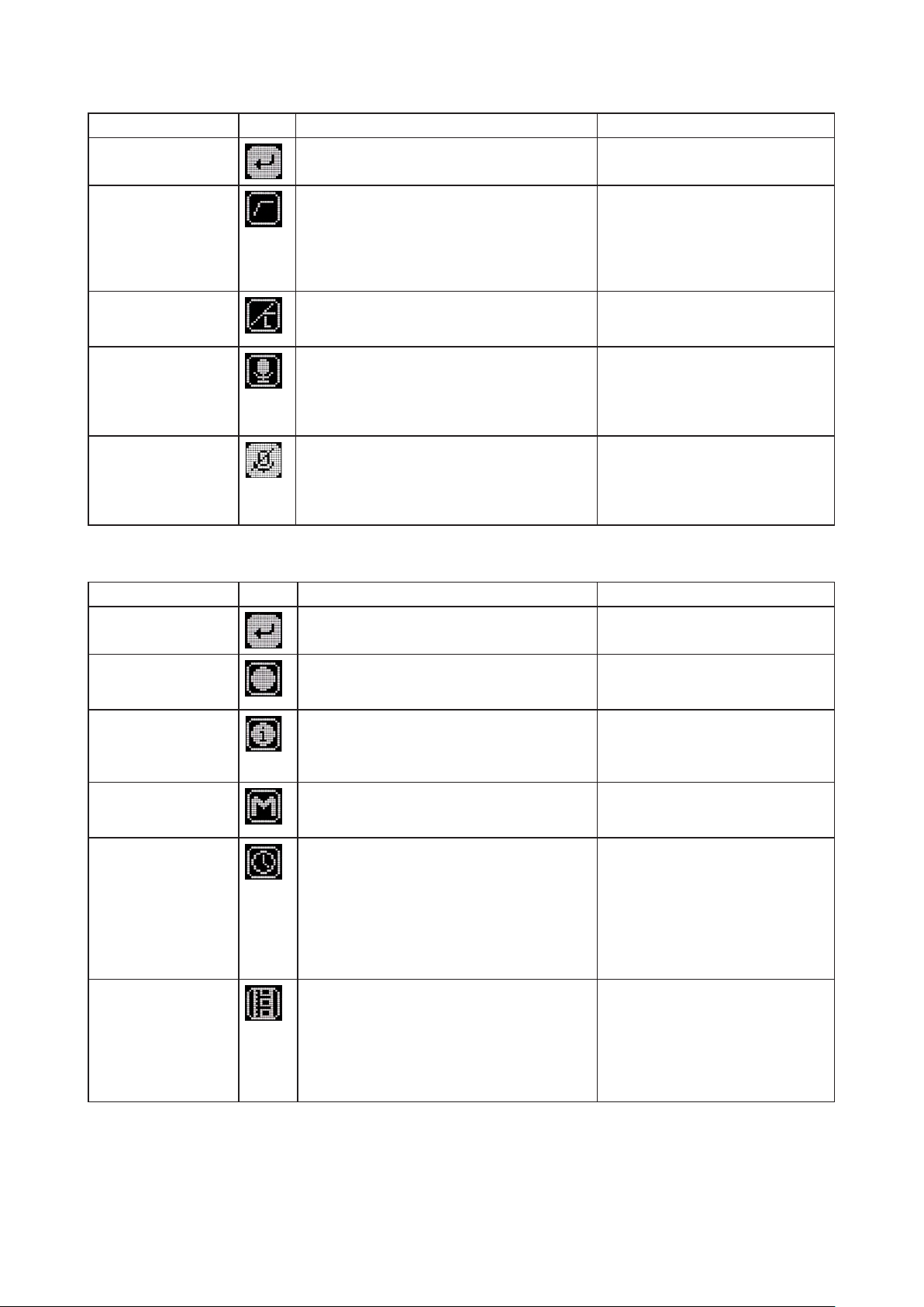
Menu Control and Menu Selections . . . . . 7
Main Menu . . . . . . . . . . . . . . . . . 7
Audio Setup Menu . . . . . . . . . . . . . 8
Record / TC Menu . . . . . . . . . . . . . 8
Settings Menu . . . . . . . . . . . . . . . 9
Display Sub-Menu . . . . . . . . . . . . . . 9
System Menu . . . . . . . . . . . . . . . . 10
Basic Operation . . . . . . . . . . . . . . . . 10
Frequency Selection . . . . . . . . . . . . 10
Channel, Sub Channel, Tune . . . . . . . . 10
Modulation . . . . . . . . . . . . . . . . . 11
Audio Input and Control . . . . . . . . . . 11
Lavalier Microphones . . . . . . . . . . . 11
Balanced Microphones with Phantom . . . 11
Line-Level Sources . . . . . . . . . . . . . 11
Audio Level Control . . . . . . . . . . . . . 11
Mute Button . . . . . . . . . . . . . . . . . 12
Recording . . . . . . . . . . . . . . . . . . 12
File Storage . . . . . . . . . . . . . . . . . 12
Timecode and Time-of-Day Clocks . . . . . 13
Time-of-Day Clock . . . . . . . . . . . . . 13
External LTC Jamming. . . . . . . . . . . . 13
Timecode Output . . . . . . . . . . . . . . 13
Remote Control . . . . . . . . . . . . . . . . 14
User Groups . . . . . . . . . . . . . . . . . . 15
Loading User Groups onto A10 Transmitters16
Firmware Updates . . . . . . . . . . . . . . . 17
SD-Utility File Conversion . . . . . . . . . . . 18
Specications . . . . . . . . . . . . . . . . . 21
Input Connector Wiring Diagram . . . . . . 22
Battery Runtime Chart . . . . . . . . . . . . 22
Warranty . . . . . . . . . . . . . . . . . . . . 22
Certications . . . . . . . . . . . . . . . . . 23
Industry Canada Conformity . . . . . . . . 23
FCC Conformity . . . . . . . . . . . . . . . 23
Declaration of Conformity. . . . . . . . . . 23
Minimize RF Exposure . . . . . . . . . . . 23
Frequency Tables . . . . . . . . . . . . . . . 24
X Frequencies (6 MHz Per TV Channel) . . 24
Y Frequencies (7 MHz Per TV Channel) . . 25
Z Frequencies (8 MHz Per TV Channel) . . 26
Channel Assignments by Region . . . . . . 26
Copyright / Doc Rev History Info
Model A10-TX. See separate documentation for A10-TX-US model.
Copyright © 2022 Sound Devices. All rights reserved.
Revision Date Description
1A Dec 2017 Initial Publication
1B Feb 2018 Added note re: Bluetooth remote range
1C Mar 2018 Edits made in sections: Specications and Certications
1D Apr 2018 Added v1.04 change (i.e. model A10-TX-D to Specs)
1E May 2018 Added v1.05 change (i.e. Orientation setting)
(1F) 2A July 2018 Minor edits (v2.00)
2B Nov 2018 Added v2.50 change (i.e. User Groups)
3A Jun 2019 Added v2.70 changes (Mute Button and Mute function)
3B Jan 2020 Added v2.80 changes (i.e. Locking/Power button changes)
3C Mar 2020 Updates for v2.90 (New RF overload indicator, conform to CSV)
4A Apr 2022 Updates for v5.00 (Modulation and SD-Utility)

- 3 -
A10-TX User Guide
Overview
• Low-noise, studio-grade balanced input for microphones and line level inputs with analogue
limiter and 48 V phantom power.
• State-of-the-art 100% digital long-range modulation delivers the longest transmission
distance of any system on the market.
• Standard and long-range modulations offer full bandwidth (10 Hz – 20 kHz), ultra-low
distortion, and high dynamic range.
• Integrated digital recorder with ultra-accurate timecode generator.
• Records to removable microSD cards.
• Simultaneous wireless transmission and recording.
• Built-in Bluetooth® to remotely control the A10-TX from an Android or iOS device using
the A10-TX Remote app.
• Powered by two AA (LR6) batteries,
Digital wireless for today and tomorrow.
The A10 Digital Wireless System is designed for the technical demands and requirements of
today’s RF-hostile, multi-channel productions. The A10-TX and A20-Mini digital transmitter
and A10-RX two channel receiver deliver broadcast-quality audio and reliable digital RF
performance with an easy, multi-system setup.
The A10’s proprietary digital RF topology and Advanced Digital Diversity System is the result of
years of research, laboratory experimentation, and customer experience. The result is a wireless
link with full 20 kHz audio bandwidth, high dynamic range, ultra-low distortion, an extremely
low 2 millisecond end-to-end delay in Standard modulation. The A10 System allows the user to
operate up to 20 channels in an 8 MHz TV channel, maximizing spectrum efciency.
With rmware version 5.00, the A10/A20 Wireless System delivers the longest transmission
distance of any system on the market.¹ The state-of-the-art, 100% digital long-range modulation
offers the same great audio quality (10 Hz – 20 kHz) as our Standard modulation scheme with a
longer range for both line-of-sight and heavy multipath transmission.
The core of the A10-TX transmitter is its low-noise, high-dynamic-range analog input. It
accepting signals from low-level lavalier microphones to balanced line-level. The 3-pin LEMO
input offers analogue limiters, 5 volt bias for lavalier microphones, as well as 12 and 48 volt
phantom power for balanced microphones.
The A10-TX transmitter includes an integrated high-quality digital recorder. Timecode-stamped
les are recorded to removable microSD cards. Free Mac and Windows software SD-Utility
converts the proprietary .mic les into monophonic, 24-bit, 48 kHz broadcast WAV les with its
associated timecode.
¹ When comparing systems with same transmit power, same antennas, and same transmission
frequency.

- 4 -
A10-TX User Guide
System Quickstart
The A10 Digital Wireless System is easy to use. Follow the steps below for basic setup and
operation.
At the Receiver
1. Fit the included straight and right-angled antennas to the A10-RX receiver.
2. Connect the receiver to a power source. It will immediately power on.
3. Using the scanning tool in the Selection menu nd an available open frequency. If multiple
wireless systems are in use, make certain to keep frequencies least 400 kHz apart.
4. Connect the audio output from channel 1, channel 2, or both to an audio input on a mixer,
recorder, camera, or PA system.
5. Ensure that the receiver audio output type and level are set based on the input type.
At the Transmitter
1. Attach the straight antenna to the A10-TX.
2. Attach an audio source to the 3-pin LEMO input connector.
3. Insert AA batteries into the A10-TX battery compartment and power on the unit with the red
On/Off button.
4. Set the audio input type to set to match the connected input.
5. Set the transmitting frequency on the A10-TX match the frequency set on the A10-RX
receiver channel.
6. Adjust the audio gain according to your environment and source, taking care not to overload
the signal. This is indicated by a red LED.
At the Receiver
1. Conrm that the blue channel power LED is solid blue.
2. Conrm that the RF status LEDs and display indicate good RF strength.
3. Conrm that the audio level at the receiver corresponds to the audio connected to the
A10-TX input.
4. The system is now ready for use.
- 5 -
A10-TX User Guide
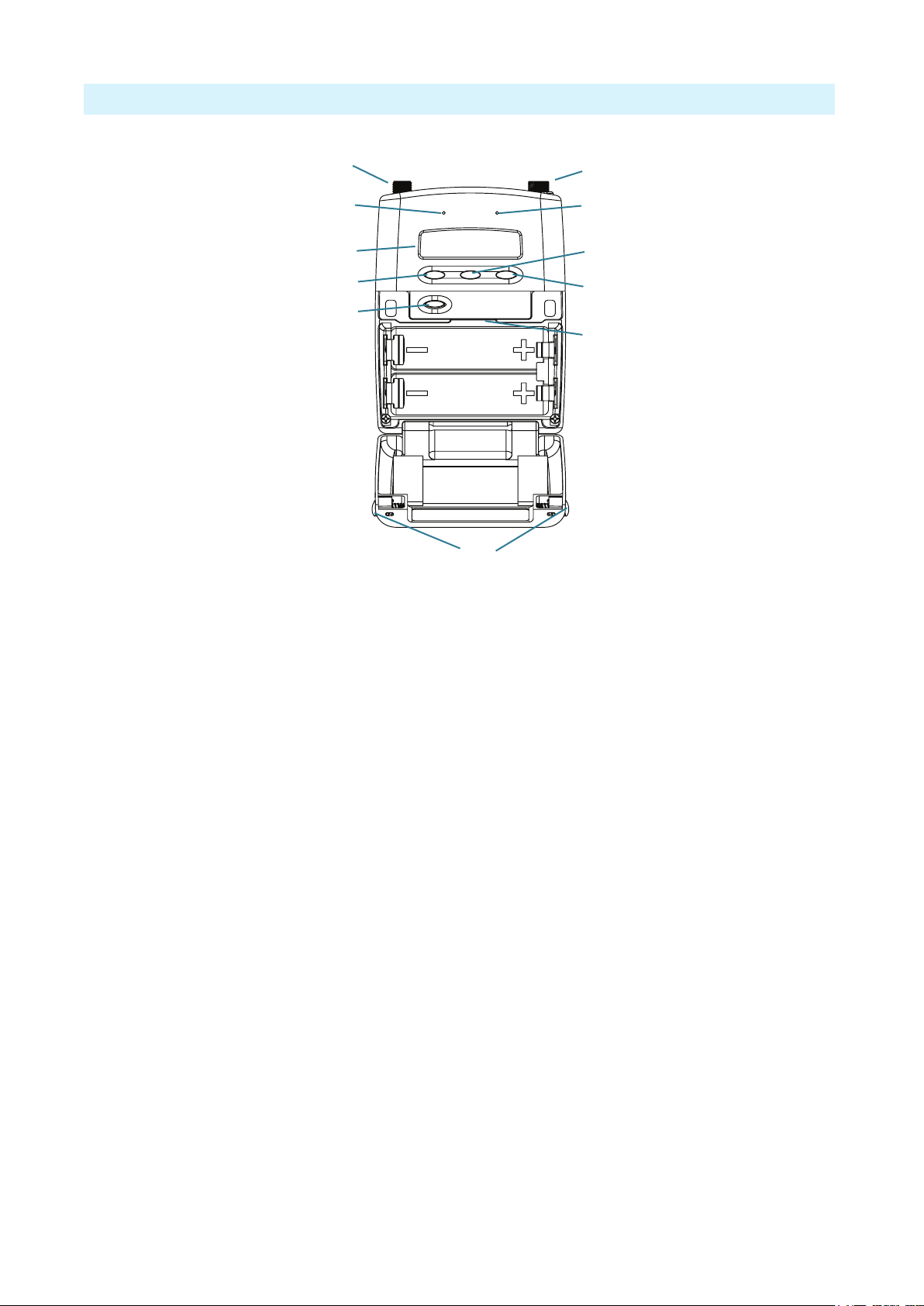
Connectors, Controls Description
2
1
3
49
12
11
6
7
10
5
8
Figure 1: A10-TX transmitter with open battery compartment
1 -Antenna Socket
SMA connector, 50 ohm, connects to includ-
ed 1/4-wave whip antenna.
2 -Power LED
Blue LED illuminates when unit is powered
on and screensave is active. Solid blue LED
can be turned off in the Menu. The LED
ashes blue when unit is in Sleep mode.
3 -Display
OLED screen. Screen automatically turns off
during operation for battery savings.
4 -Left Button
Moves selection in menu to the left, or dec-
rements values. When Mute Button option is
On, press and hold to mute/unmute.
5 -Power Button
Press to power on the unit. Press and hold to
power down the unit. Press and hold while
holding Right button to lock/unlock the unit.
6 -Audio Input Connector
Balanced LEMO-3 connector. Accepts mul-
tiple audio input types including unbalanced
lavalier, balanced microphone, balanced line.
Also used for timecode input and output.
7 -Input Overload LED
Red LED illuminates when input signal is
3dB before clipping.
8 -Menu Button
Enters the menu selection. Also used to select
options in the menu.
9 -Right Button
Moves menu selection to the right, or incre-
ments values.
10 - microSD Card Slot
The card slot is used to record les and load
rmware updates on the unit.
11 - Battery Tray
Accepts two AA LR6 batteries.
12 - Battery Door Latch
Press both latches to open the battery door.

- 6 -
A10-TX User Guide
Powering
The A10-TX is powered by two AA (LR6) batteries. For the longest runtime, use Lithium
primary cells. The transmitter also accepts alkaline primary and Nickel Metal Hydride
rechargeable batteries. Select the battery type used in the menu to ensure that the battery
condition is indicated accurately in both the transmitter display and receiver.
1. Open the battery compartment by simultaneously pressing both mechanical releases of the
battery door latch. (See Figure 1.)
2. Insert two fresh AA type (LR6) batteries. Note correct battery polarity.
3. Momentarily press the red On/Off button. The blue power LED will light and the display will
illuminate. The transmitter is now powered on.
4. To turn the transmitter off, press and hold the red button until the “turning off’ progress bar
completes and the unit goes dark.
Main Display
After powering on the A10-TX the display shows the following.
Battery Condition
Input
Gain
RF Output
Power
Frequency in MHz
Frequency as
Channel–Sub Channel
Input Level
Meter
Record
Indicator
• RF Output Power - three power levels are indicated, Low (10 mW), Medium (20 mW),
High (50 mW)
• Input Gain - gain applied to the input source, in dB
• Battery Condition - shows the battery voltage level of the transmitter batteries, ve-
segments
• Frequency in MHz - the transmitting frequency is shown
• Frequency in Region–Channel–Sub Channel - the transmitting frequency is shown in
region, channel, and sub channel.
ªX, Y, and Z regions are selected by the TV Channel Map setting.
• Input Level Meter - shows audio input signal level
• Record “dot” Indicator - ashes in top left corner when recording is underway
Press the Left button, to view the name of the transmitter. The serial number of the transmitter
is the default name of the transmitter. The transmitter name may be changed via the A10-TX
Remote app.
By pressing the Right button, the user can view the recording status, which displays the current
le name, time elapsed, time remaining, timecode and current frame rate.
- 7 -
A10-TX User Guide
Menu Control and Menu Selections
The A10-TX transmitter is controlled through its menu. Enter the menu via the centre Menu
button. Once in the menu, the Left and Right buttons toggle among options, and the Menu button
makes the selection.
The Menu Lock feature on the A10-TX provides a way to lock the buttons. Press and
hold the Power button while holding the Right button to lock/unlock access to menu
settings. When menu access is locked, a Lock icon (shown right) appears in the main
display.
ªWhen locked, the Power button remains active.
Main Menu
Selections Icon Description Options
Exit Returns to the main display screen.
Frequency Sets the transmitter’s frequency. Frequency
selection and channel increments change based on
the region of operation the unit is set.
• TV Channel
• Sub Channel
• Tune Frequency increments in 25 kHz
steps
Audio Gain Controls the gain range of the audio input. Gain
range is input type dependent. Gain control is in 1
dB increments.
• Lavalier: 0 dB to +40 dB
• Line setting: -10 to 16 dB
• Mic setting: 16 to 40 dB w/20dB pad
• Mic setting: 36 to 60 dB
Audio Setup Enters the Audio Setup sub-menu. • Low Cut
• Limiter
• Lav / Mic / Line
• Mute Button
Record / TC Enters the Record / TC sub-menu. • Record / Stop
• File Info
• TX / Record Mode
• Timecode
• Frame Rate
Privacy Activates transmission privacy with a four-number
key set on the transmitter and receiver. When
active, the receiver must be set to the corresponding
key for audio to pass.
New Key option generates a key. The key symbol
is displayed on main default screen when privacy
is active.
• New Key - generates new key
• Off - encryption cleared, set to ----, not
active
Settings Enters the Setting sub-menu. • Bluetooth
• RF Power
• Modulation
• Battery Type
• User Groups
• TV Ch Map
• Display
System Enters the System sub-menu. • Sleep
• Lock Menu
• Set Time/Date
• Format Card
• Restore
• Info
• Update Firmware
- 8 -
A10-TX User Guide
Audio Setup Menu
Selections Icon Description Options
Exit Returns to the main menu.
Low Cut Activates a low frequency cut lter to the audio
input. 18 dB/octave
• Off
• 40 Hz
• 60 Hz
• 80 Hz
• 100 Hz
• 200 Hz
Limiter The limiter reduces peak levels of the analogue
audio input before digital conversion to prevent
audio overload. The recommended setting is On.
• On
• Off
Lav / Mic / Line Selects the input type at the LEMO-3 connection.
ªFor Mic/Line, the AC-BAL-XLR accessory is
required.
• Lav
• Mic
• Line
• P48 - mic level with 48 V phantom
• P12 - mic level with 12 V phantom
Mute Button Enables or disables mute button shortcut. • On - Transmitter mute can be toggled
on or off by holding Left or Right
button for 1 second.
• Off - Shortcut is disabled.
Record / TC Menu
Selections Icon Description Options
Exit Returns to the main menu.
Record Select Record to enter Record mode (This begins
recording). The Record status is remembered
across sleep and power cycles.
• Record (displayed while Stopped)
• Stop (displayed while Recording)
File Info Shows important information about the le being
recorded.
• Time Elapsed
• Time Remaining
• Timecode
• File Name
TX / Record Mode Select the operational mode of the A10-TX. • TX / Rec - simultaneous wireless
transmission and recording
• Rec Only - recording function only
Timecode Enter Timecode menu.
Timecode values from either the attached external
timecode generator or the internal generator are
shown.
ªWhile in this menu, wireless transmission is
suspended, and timecode may be sent via AC-
TCBNC-OUT or AC-TCLEMO accessories.
• Time of Day
• External
• Jam - applies external timecode to the
internal generator.
ªJamming to an external timecode
source requires the AC-TCBNC-IN
or AC-TCLEMO accessories.
Frame Rate Sets the frame rate of the timecode clock. Select a
rate that matches the incoming timecode rate.
ªRejam is required after setting frame rate.
• 23.98
• 24
• 25
• 29.97
• 29.97 DF
• 30
• 30 DF

- 9 -
A10-TX User Guide
Settings Menu
Selections Icon Description Options
Exit Returns to the main menu.
Bluetooth Toggles Bluetooth On or Off. Bluetooth offers
external control of the A10-TX via the A10-TX
Remote App (for iOS or Android).
• On
• Off
RF Power Sets the RF output power of the transmitter. • Low - 10 mW
• Med - 20 mW
• High - 50 mW
Modulation Selects Standard or Long Range Modulation.
ªThe Modulation setting must match between
the A10-TX and the A10-RX in order for the
transmitted signal to be received.
• Std (Standard)
• LR (Long Range)
Battery Type For accurate display of battery condition on the
transmitter and receiver select the battery type
from the available options.
• Alkaline
• NiMH
• Lithium
User Groups Sets whether transmitter utilizes user groups (User)
or manual frequency selection (Factory).
• User
- Use
- Load New
• Factory
TV Ch Map Selects the TV channel spacing in MHz to ensure
channel selection cooresponds to a specic
geographic region. See frequency chart.
• X – 6 MHz
• Y – 7 MHz
• Z – 8 MHz
Display Enters the Display sub-menu. • Brightness
• Blue LED
• Orientation
Display Sub-Menu
Selections Icon Description Options
Exit Returns to the main menu.
Brightness Sets the brightness of the OLED screen Five increments, 1–5,
5 is brightest
Blue LED If set to On, the LED illuminates blue when
powered on and screensaver is active.
• On
• Off
Orientation Sets orientation of display — ideal for when
transmitter is attached upside down on boom pole.
• Normal (default)
• Flipped

- 10 -
A10-TX User Guide
System Menu
Selections Icon Description Options
Exit Returns to the main menu.
Sleep When selected, the A10-TX goes into low-power Sleep
mode. The blue LED ashes when the unit is in a sleep state.
The unit returns to normal power operation when any button
is pressed or the transmitter is activated from the A10-TX
Remote App.
• Sleep
Lock Menu Activates a button lock to prevent unintentional changes to
menu selections.
• Unlock
• Lock
Set Time / Date Sets the time and date of the realtime clock. This value is
applied to any recorded les.
Format Card Deletes all les and data present on the inserted microSD
card and prepares it for new recordings.
OK - begins formatting process.
Restore The restore function allows the user to reset the A10-TX to
the factory default settings.
Info Shows numerous attributes of the transmitter. • Serial Number
• Firmware Revision
• Frequency Band
Update (Firmware) Updates the rmware of the transmitter using a rmware
.PRG le on the microSD card.
Basic Operation
Frequency Selection
The A10 Digital Wireless System operates in the UHF frequency band from 470 to 694 MHz.
There are three models (two in some geographic markets) of the A10-TX transmitter to cover
this frequency range.
Multiple A10 Digital Wireless systems can be used simultaneously on nearby adjacent
frequencies without worry of intermodulation interference since the A10 Digital Wireless System
and its digital RF transmission is inherently immune to intermodulation. Systems can be used
together when separated by at least 400 kHz. Use the scan tool on the A10-RX receiver to search
for available frequencies.
ªWhen using A10 Digital Wireless systems in conjunction with analogue RF systems, an
intermodulation plan needs to be addressed for analogue receivers.
Channel, Sub Channel, Tune
To simplify frequency selection, frequencies are divided into channels and sub channels.
Frequencies corresponding to channels and sub channels depend on the TV Channel Mapping
selected in the Systems menu. Three options are available, 6, 7, and 8 MHz spacing, X, Y, and Z
respectively. These three settings generally correspond to three main geographic regions, USA,
Australia/New Zealand, and Europe, respectively.
• Channel - corresponds to broadcast television channels used in geographic regions.
Depending on the selected channel mapping, channels cover 6, 7, or 8 MHz.
• Sub Channel - channels are divided in 400 kHz increments called sub channels to speed up
frequency selection. The number of sub channels depends on the channel mapping selected.

- 11 -
A10-TX User Guide
• Tune - specic frequencies within the transmitter’s tuning range can be selected in 25 kHz
increments.
To change TV channels, use the Left button to highlight the TV
Channel. Press the centre Menu button to select the TV channel.
Select Sub Channel until the desired sub-channel is selected.
ªRemember, for a given channel / sub channel, the actual
frequency will change depending on the TV Channel Mapping setting.
The frequency is displayed with an asterisk (*) when the tune value does not fall within the pre-
allocated sub channel.
See the Frequency Tables in this guide for a complete list of frequencies corresponding to the
channel and sub channel selections.
Modulation
Modulation can be set to Standard (Std) or Long Range (LR) in Menu > Settings > Modulation.
When compared to Standard Modulation, Long Range Modulation has better sensitivity. This
increased sensitivity results in more robust performance in challenging RF environments.
ªThe Modulation setting must match between the A10-TX and the A10-RX in order for the
transmitted signal to be received.
Audio Input and Control
The A10-TX input accepts a wide range of audio input types, including lavalier microphones,
balanced microphones, and balanced and unbalanced line level signals. 12 V and 48 V phantom
power is available for balanced microphones. The Selection Menu offers options for input type,
limiters, and low cut lter.
Lavalier Microphones
Unbalanced lavalier microphones wired in two-wire mode, are directly compatible with
the A10-TX input. When connected, the A10-TX auto-detects the presence of a lavalier
microphone.
Balanced Microphones with Phantom
Balanced microphones, including phantom powered shotgun microphones, can be connected
to the A10-TX. 12 V and 48 V phantom power are available for microphones requiring it. For
microphones that can properly operate on 12 V phantom, such as the Schoeps CMIT, select 12
V phantom to signicantly increase battery runtime.
Line-Level Sources
Wireless systems are often used as “camera hop” systems. For most camera hop applications
the output of a eld mixer is connected to a wireless transmitter. The wireless receiver output
is connected to the camera input. The line level input selection simplies using the A10
System as a camera hop. Select Line in the Selection Menu to accept balanced or unbalanced
line level inputs.
ªTo connect balanced microphone or line level sources to the A10-TX, a cable wired as
described in the specications or the AC-BALXLR cable is required. This connects the shell
of the LEMO connector to pin-1 of an XLR connector.
Audio Level Control
Input levels are controlled from the Audio Gain option in the Selection Menu. The gain range
available is source-dependent as follows:

- 12 -
A10-TX User Guide
• Lavalier setting: 0 dB to 40 dB, 1 dB increments
• Line setting: -10 to 16 dB, 1 dB increments
• Mic setting (with 20 dB pad): 16 to 40 dB, 1 dB increments
• Mic setting (with no pad): 36 to 60 dB
Set input levels so that the limiter is active only on the strongest peaks.
Mute Button
When the Mute Button function is enabled, holding the Left button for 1 second
toggles Mute on or off. While Muted, the transmitter LED ashes red. The paired Receiver
channel display Muted on the channel screens. Audio is muted at the transmitter input, this
means both recorded and transmitted audio will be silent.
Antenna
The SMA antenna connector is used to mount the included 1/4-wave whip antenna. The use of
any other type is forbidden.
For best operation and transmission power with the included 1/4-wave antenna keep it in the free
eld. If worn on a body keep the antenna away from direct contact with the wearer’s body.
Recording
The A10-TX incorporates a data recorder that stores encoded digital waveform and timecode
data in proprietary, data-compressed binary MIC les. The MIC les generated directly on
the A10-TX are not usable until converted. Sound Devices provides a free Windows and Mac
app called SD-Utility that converts MIC les into Broadcast WAV les. See SD-Utility File
Conversion for more details.
After conversion, a usable 48 kHz digital audio WAV le is made. Files recorded in the A10-TX
are approximately 1/3 the size of WAV les generated from corresponding MIC les, saving
valuable space on the microSD card. Files have a maximum duration of six hours. After six hours
the le is automatically split into another recording. Resulting WAV les are sample accurate
across le splits.
To begin recording on the A10-TX:
»Select Menu > Record/TC > Record.
Recording can also be initiated from the A10-TX Remote App. The default le name of the
MIC le is the serial number of the A10 transmitter; however, the le name may be renamed
via the A10-TX Remote app. For more information, see Remote Control.
An indicator ashes in the display to show that the A10-TX is recording. This indicator is also
shown on the A10-RX, in the TX data screen, accessed by pressing the Right button on the
A10-RX receiver.
From the main screen on the transmitter, pressing the Right button shows record status
information, such as le name (when recording), le duration, remaining record time, timecode
values, and frame rate.
File Storage
Proprietary MIC les generated by the A10-TX are stored on FAT32-formatted microSD cards.
The microSD card slot is located in the battery compartment and is accessed by removing the
battery nearest the display.
If no microSD card is inserted in the unit, a ‘No card detected’ message is indicated.

- 13 -
A10-TX User Guide
New cards, or cards with material that can be overwritten, can be formatted in the A10-TX.
ªFormatting deletes all existing recordings present on the card.
There is no provision to manage les from the A10-TX. File management, including le
renaming and individual le deletion, is done when the microSD card is mounted to a computer
via a card reader.
Timecode and Time-of-Day Clocks
The A10-TX includes high-precision internal clocks to maintain time-of-day/date and SMPTE
timecode. These clock runs continuously when AA batteries are in the unit and draw negligible
current (less than 1 uA). The A10-TX design incorporates a supercapacitor to power the time-
of-day clock for several days in the absence of batteries. The supercapacitor reaches full charge
when batteries have been in the unit for ve minutes.
Time-of-Day Clock
The time and date clock holds time and date for les recorded on the A10-TX, and can be
used for the Time of Day timecode value.
To set time and date:
1. Enter the Selection Menu option real time clock. (Menu > System > Set Time/Date)
2. Use the centre Menu button to move between year, month, day, hours, and minutes. Use
the Left and Right buttons to change the values.
3. Press the centre Menu button to select the Return arrow and view current values. Press
again to exit.
External LTC Jamming
External LTC timecode can be applied to the A10-TX to synchronize its internal timecode
clock. Synchronization of timecode clocks is called “jam syncing”. To jam the A10-TX
timecode clock, navigate to Menu > Record/TC > Timecode in the Selection menu. Connect
an LTC timecode source to the 3-pin LEMO™input connector using either the AC-TCLEMO
or AC-TCBNC-IN cables. The A10-TX will jam its timecode clock from the incoming
timecode signal.
ªWhile in the Timecode menu, RF transmission and recording are deactivated on the A10-TX.
The timecode clock remains accurate when the transmitter is powered or in standby mode.
When the unit is powered down accurate timecode is held for six hours. After six hours the
timecode clock is reset to its default value.
Timecode Output
The A10-TX 3-pin LEMO connector also functions as a timecode output connection. In the
Selection menu navigate to Menu > Record/TC > Timecode. While in this screen timecode
can be sent out of the A10-TX using the AC-TCLEMO or AC-TCBNC-OUT cables.
Upon exiting the timecode menu the 3-pin LEMO reverts back to the selected lavalier,
microphone, or line input. RF transmission is reactivated and recording is available.
- 14 -
A10-TX User Guide
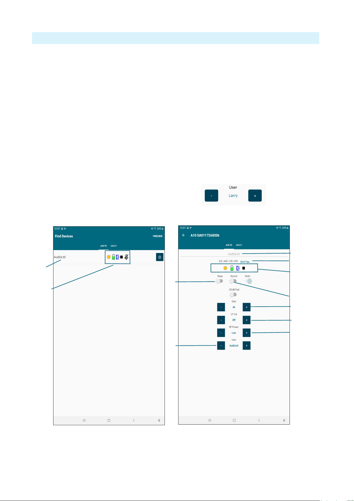
Remote Control
The A10-TX can be remotely controlled from an Android or iOS device running the A10-TX
Remote app. The app is available as a free download from the Google Play store and iOS App
store, respectively.
With the A10-TX Remote app, you can:
1 - Change the transmitter’s name; the serial
number is used at default. When using User
Groups, the user name is displayed.
2 - View timecode and frame rate
3 - Monitor Sleep status, Battery status,
Bluetooth signal strength, Record status,
Mute Status
ªTouch the Circle-I icon to send
identication signal to the transmitter.
4 - Turn Sleep mode On/Off
5 - Mute/Unmute the transmitter
6 - Start/Stop recording at the transmitter
7 - Adjust Gain
8 - Set the low-cut lter
9 - Adjust RF Power
10 - Change TV Ch, Sub Ch and Frequency
ªWhen a user group is loaded, the TV Ch/
Sub Ch/Frequency section changes to
User, displaying the user names between
+ / - Selection buttons as shown below:
1
3
4
10
7
8
6
9
1
2
3
Touch the name (left image) to access more information (right image) about the transmitter.
ªThe Bluetooth operational range is very short. Maintain close proximity to the transmitter
for reliable connection.

- 15 -
A10-TX User Guide
User Groups
The User Groups feature allows for easy, intuitive naming of specic frequencies for each A10
transmitter used on set, and grouped together for faster tuning. The operator of an A10 receiver
may then easily switch between transmitters by choosing alphanumeric names, such as “Jack”
and “Jill”, instead of having to remember and manually tune to different, specic numerical
frequencies.
For instance, a producer or director may want to monitor several different actors’ wireless
transmitters. Rather than having to keep a list of all of their frequencies, each transmitter may be
pre-assigned a frequency and given an actor’s name. Then only those pre-assigned frequencies
that have been named will be available as possible options for tuning.
User Group les are created using SD-Utility—a Windows and Mac application available for
free download from the Sound Devices website.
https://www.sounddevices.com/download/?prod=sd-utility
Once created, the User Group les are uploaded to A10 transmitters and receivers.
To create a new user group:
1. Open SD-Utility on your computer.
2. Do one of the following:
• On a Mac, select User Group File > New.
• On a PC, select File > User Groups > Create a new le.
3. Name the new group.
4. Select a range of frequencies via the Band drop-down list. Options include A, B, C, D and
Any. This will automatically restrict users in the group to the frequencies within that band.
Selecting Any will make frequencies within all bands available for assignment to users in the
group.
ªAll A10-TX will have the available bands listed on the printed label inside the battery
compartment door as well as displaying the frequencies capable of being generated by the
transmitter in Menu > System > Info.
5. Select OK. The User Group Editor screen appears with elds for the rst user (U1) available.
6. Enter a Name and Frequency for U1 in the elds provided. The A10-TX transmitter’s serial
number is optional.
Entry of ineligible frequencies (or characters) will cause the text in the eld to appear red.
SD-Utility automatically lls in .000 as the subchannel variable for frequencies entered
as a whole number. SD-Utility automatically follows the best-practice method of spacing
adjacent transmitters by at least one subchannel, preventing possible interference from other
transmitters.
7. Click Add (on a PC) —or the Plus (+) button on a Mac— to add the user to the group. This
also adds a new line for the next user (U2, U3, etc). Each user in a group can be given a name
and frequency, which after upload, will then be displayed on A10 receivers and transmitters.
Each group can have up to 32 users.

- 16 -
A10-TX User Guide
SD-Utility supports the creation of up to eight user groups, each with a max of 32 users, per
Audio Limited User Group (ALUG) le.
To add additional user groups:
1. In SD-Utility, select Add Group.
2. Name the new group and select the band of frequencies for the group.
3. Add users (dening name and frequencies) to the group.
Audio Limited User Group les (ALUG) may be saved for future use and modication. When
saving the ALUG le, SD-Utility will default the le name to the rst User Group name in the
drop-down list.
To load an ALUG le into SD-Utility:
1. In SD-Utility, select User Group File > Open.
2. Choose an ALUG le on your computer.
To remove a user group:
1. In SD-Utility, select a User Group in the drop-down list.
2. Select Remove Group.
Loading User Groups onto A10 Transmitters
A user group is transferred to the A10-TX via the microSD card inserted into the transmitter.
ªFor instructions on sending a user group to A10 receivers, see the A10-RX User Guide.
To load a user group on an A10-TX:
1. If the microSD card has not been formatted by the transmitter already, do so by inserting it
into the transmitter and select System > Format Card > OK.
2. Remove the microSD card from the transmitter and insert it into your computer.
3. Drag and drop the entire ALUG le to the microSD card.
ªSaving an ALUG le from the SD-Utility application only saves the user group selected from
the drop-down list.
4. Eject the microSD card and insert it back into the transmitter.
5. Press the centre Menu button, then select Settings > User
Groups > User > Load New.

- 17 -
A10-TX User Guide
6. Use the left and right buttons to navigate through the available User Groups. Press the centre
button to select and load the user group.
With a user group loaded, the transmitter’s Frequency control changes between different users in
the group and their pre-assigned frequencies.
To dial in a specic user (and its frequency):
1. Press the center Menu button on the transmitter.
2. Select Frequency.
3. Press the left or right buttons to navigate through available user
names, then press the centre button to select the user names.
The frequency appears along with the name and user number
(1-32).
ªWhile in User mode, only user group frequencies are selectable. To revert back to factory
frequency selection, set Menu > Settings > User Groups to Factory.
Firmware Updates
Periodically Sound Devices issues new rmware for the A10-TX transmitter. Make certain to
register your product at the Sound Devices website to receive rmware update notications.
Firmware is installed on the A10-TX using the A10-TX menu. Download the latest rmware
PRG from the Sound Devices website at:
https://www.sounddevices.com/download/
A Change List of new features for the latest rmware can also be found on this webpage..
To update rmware:
1. Download the new rmware PRG update le from the Sound Devices website and copy the
le onto an approved microSD card that has been formatted in the A10-TX.
2. Insert the microSD card in the unit.
3. Insert fresh AA batteries in the unit.
4. Power on the A10-TX. Then Enter the System menu and choose Update. The unit will
indicate the revision of rmware to update.
5. Conrm that you want to update the unit. The update process begins after conrmation.
6. Do not power down the unit until instructed to do so. When the update process has completed
the following message displays on the screen:
Update Success
Unit will power down.
OK
Press the centre button to select ‘OK’. The A10-TX automatically powers off.
7. Press the red power button to power on the A10-TX. Verify the revision of rmware on the
unit from Menu>System>Info.
- 18 -
A10-TX User Guide
SD-Utility File Conversion
Sound Devices SD-Utility is a companion application for MacOS and Windows. This
application can be used to process MIC les recorded by the A10-TX into standard
Broadcast WAV les. The application offers various export options to suit to the
given workow.
A10-TX MIC les can be renamed, snipped by timecode values, conformed to a CSV Sound
Report, exported as WAV, and more.
SD-Utility is also a companion application for the Audio Ltd A10-RX and the Sound Devices
A20-Mini. For details specic to those products, please refer to their respective user guides.
Installing SD-Utility
1. Download the SD-Utility Installer for MacOS or Windows from:
https://www.sounddevices.com/download/?prod=sd-utility
2. Open the installer and install the application by following the on-screen instructions.
Minimum operating requirements:
MacOS 10.11+, 64-bit
Windows 10+, 64-bit

- 19 -
A10-TX User Guide
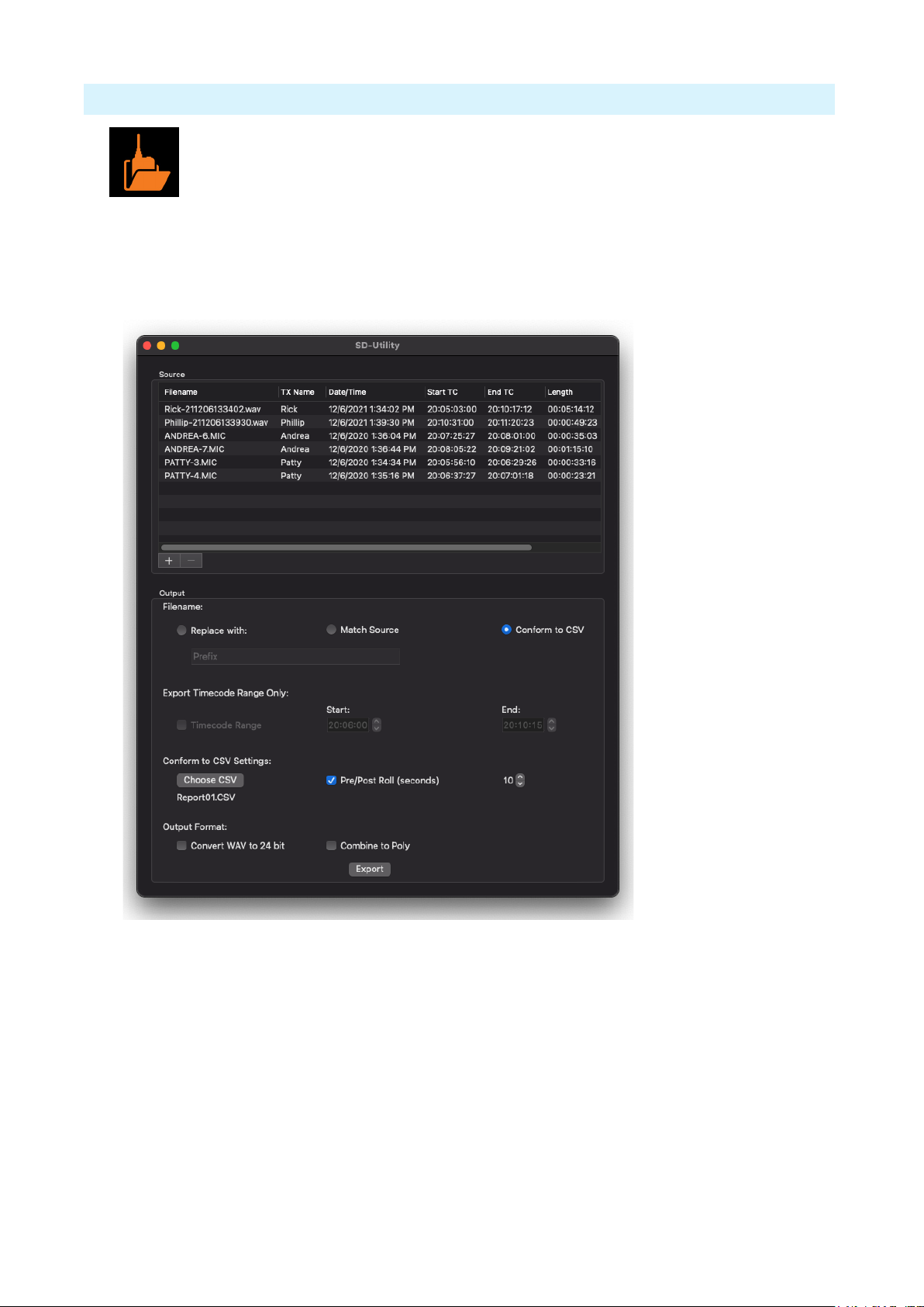
Importing Files into SD-Utility
SD-Utility accepts monophonic WAV and RF64 WAV les recorded by the A20-Mini or MIC
les recorded by the Audio Ltd A10-TX. There are three methods for importing les into SD-
Utility.
• Drag-and-drop WAV or MIC les or volumes/folders containing MIC and/or WAV les into
the Source window.
• Navigate File > Add and select MIC and/or WAV le(s) for import.
• On the bottom left of the Source window, click + in Mac or Add in Windows, then select
le(s) for import.
The Source window displays the following information for all imported les.
• Filename
• Transmitter name
• Date and time of le creation
• Start timecode
• End timecode
• Length of recording
• Frame Rate
Removing les from the Source Window
There are three methods for removing MIC and/or WAV les from the Source window.
• Highlight the le(s) to be removed from the Source window, then click - on Mac or Remove
on Windows.
• Highlight the le(s) to be removed from the Source window, then navigate File > Remove.
• Highlight the le(s) to be removed from the Source window, then press the Delete key.
Organizing Source Files
Click on a Information Header cell to order the list of les in the Source Window by information.
For example, click the Start TC cell to arrange the les by timecode start times from lowest to
highest. Click again to reverse the order from highest to lowest.
To manually order the list of source les, click and hold a le row and drag it into the desired
position.
Selecting Files to Export
Highlight the le(s) to process and export from the Source window. Multiple les can be selected
using keyboard modiers, Apple and Shift in MacOS, Ctrl and Shift in Windows. If no les are
selected, processing is applied to all les in the Source window. Naming of Processed Files
Exported WAV les will be named according to the Filename selection.
Match Source uses the source le’s name in the exported WAV le.
Replace with allows the exported le to be named based on the custom entry.
Conform to CSV uses the take information from a CSV Sound Report to determine the exported
le names. See Conforming A10-TX Files to CSV sound reports.

- 20 -
A10-TX User Guide
Creating Shorter WAV Files Based on Timecode Range
When a shorter WAV le is needed than the original recording, you can use the Timecode Range
feature to create a shorter WAV le. The length and content of the exported le is based on the
entered timecode start and stop times.
1. Highlight the source le(s) from the Source window.
2. Select the Timecode Range check box.
3. Enter valid timecode start and end times. The values must fall within the range of the source
le.
4. Select Export.
Conforming A10-TX MIC Files to CSV Sound Reports
CSV sound report les generated by Sound Devices recorders can be used to extract only
relevant audio from the A20-Mini WAV or A10-TX MIC les. Audio is extracted and a new
WAV le is created based on the timecode in/out values of takes listed within the CSV.
The exported WAV le names and embedded metadata are changed to match the lenames and
metadata of the corresponding takes in the CSV sound report.
Adding Pre- and Post-Roll
Adding Pre- and Post-Roll to conformed les can benet post production with access to audio
just prior to and following head and tail slates.
To add pre- and post-roll to conformed WAV les, select the Pre/Post Roll check box and enter a
value from 0 to 10 seconds in 1 second steps.
If the source le does not contain audio data for the duration of the pre- or post-roll location, the
exported le will begin and end at the closest point to the pre- and post-roll location where audio
data is present.
Combining to Poly
Combine to Poly allows for the export of a single polyphonic WAV le containing audio tracks
from each relevant transmitter for takes of the CSV Sound Report or a select timecode range.
Select the Combine to Poly check box to export a polyphonic WAV le, leave unchecked to
export monophonic WAV les for each transmitter.
Combine to Poly is available with the following setups:
• Conform to CSV is selected
• Replace with: and Timecode Range are selected
The interleave order of the polyphonic WAV tracks are determined by the order of the les in
the Source Window. Silence is written to a track of the exported polyphonic WAV le whenever
audio data is not available from the source les.
This manual suits for next models
1
Table of contents
Other Sound Devices Transmitter manuals


