Southwire 41170S User manual

12/14 Rev. 1
41170S manual
Contents Made in China
Product distributed by Southwire Company, LLC
One Southwire Drive, Carrollton, GA 30119
©2014 Southwire Company, LLC. All rights reserved.
southwiretools.com
1-855-SW-T00LS
Toll Free Technical Help
Línea de Ayuda Técnica Gratuita
Scan for warranty informaon
and to access our mobile site.
Escanea para información de garana
y acceso a nuestro sio móvil.
TESTING EQUIPMENT
E361819
Operating Instructions
41170S Voltage/Continuity Tester
Instrucciones de uso
Comprobador de Voltaje/Continuidad 41170S

Introduction
1
The Southwire 41170S provides a fast and simple method
of testing continuity, AC or DC voltage up to 600V.
It also indicates rotary field direction in three phase circuits.
A built-in flashlight can be used to illuminate the work area.
This instrument is fully tested and calibrated, and with proper
use, will provide many years of reliable service.
WARNINGS
• Read, understand and follow the Safety Rules and Operating
Instructions in this manual before using this instrument.
• The tester’s safety features may not protect the user if not
used in accordance to the manufacturer’s instructions.
• Keep fingers away from the metal probe tips when taking
measurements.
• Comply with all safety codes. Use approved personal
protective equipment when working near live electrical
circuits - particularly with regard to arc-flash potential.
• Use caution on live circuits. Voltages above 30V AC RMS,
42V AC peak, or 60V DC pose a shock hazard.
• Do not use if the instrument or test leads appear damaged.
• Verify tester’s operation by measuring a known voltage.
• Do not use the tester in wet or damp environments or during
electrical storms.
• Do not use the tester near explosive vapors, dust or gasses.
• Do not use the tester if it operates incorrectly.
Protection may be compromised.
• Do not apply voltage that exceeds the tester’s maximum
rated input limits.
2
Input Limits
Function Maximum Input
Voltage DC, Voltage AC
Continuity
Single Pole Voltage Detection
Rotary Field Indication
600V
600V
600V
600V
International Safety Symbols
Potential danger. Indicates the user must refer to the
manual for important safety information
Indicates hazardous voltages may be present
Equipment is protected by double or reinforced insulation
Indicates the terminal(s) so marked must not be connected
to a circuit where the voltage with respect to earth ground
exceeds the maximum safety rating of the meter
Indicates the terminal(s) so marked may be
subjected to hazardous voltages.
MAX
600V
Brief Description Typical Applications
Category
Rating
Single phase receptacles
and connected loads
Three phase circuits and
single phase lighting
circuits in commercial
buildings
- Household appliances, power tools
- Outlets more than 30ft (10m) from a CAT III source
- Outlets more than 60ft (20m) from a CAT IV source
- Equipment in fixed installations such as 3-phase
motors, switchgear and distribution panels
- Lighting circuits in commercial buildings
- Feeder lines in industrial plants
- Any device or branch circuit that is close to a
CAT III source
CAT II
CAT III
Safety Category Ratings
The measurement category (CAT) rating and voltage rating is determined by a combination of the meter,
test probes and any accessories connected to the meter and test probes.
The combination rating is the LOWEST of any individual component.

3
Maintenance
This Tester is designed to provide years of dependable service,
if the following care instructions are performed:
1. KEEP THE TESTER DRY. If it gets wet, wipe it off.
2. USE AND STORE THE TESTER IN NORMAL TEMPERATURES. Temperature
extremes can shorten the life of the electronic parts and distort or melt
plastic parts.
3. HANDLE THE TESTER GENTLY AND CAREFULLY. Dropping it can damage the
electronic parts or the case.
4. KEEP THE TESTER CLEAN. Wipe the case occasionally with a damp cloth.
DO NOT use chemicals, cleaning solvents, or detergents.
5. USE ONLY FRESH BATTERIES OF THE RECOMMENDED SIZE AND TYPE.
Remove old or weak batteries so they do not leak and damage the unit.
6. IF THE TESTER IS TO BE STORED FOR A LONG PERIOD OF TIME, the batteries
should be removed to prevent damage to the unit.
Tester Description
1. Test Probe (
–
) L1
2. Test Probe (
+
) L2
3. Flashlight
4. LED voltage level indicators
5. LED for single-pole test
6. LED for hazardous voltage warning
7. LED for Right rotary field indication
8. LED for Left rotary field indication
9. LED for continuity
10. Self-test switch (AUTO TEST)
11. Flashlight on button
12. Battery case
13. LED for +DC polarity
14. LED for -DC polarity
(NOTE: 13. LED and 14. LED illuminate
for AC voltage indication)
1. 2.
3.
Indicators/Warnings
4.
5.
6.
7.
8.
9.
10.
11.
12.
14.
13.
4
Operation
Function Test/Self-Test
Press the “AUTO TEST” button. The beeper will sound and the continuity LED
and all 8 voltage LEDs will illuminate. Replace the batteries immediately if the
tester is not functioning correctly.
To avoid electric shock, disconnect the test leads from any
voltage source before performing the self-check test function.
WARNING:
NOTE: The “ ” hazardous voltage warning LED will illuminate if the voltage
exceeds 50 volts even if the batteries are low or have been removed.
AC/DC Voltage Measurements
1. Touch the test probes across the
circuit being measured.
2. The tester will turn on automatically
if the voltage exceeds 6 volts.
3. The LEDs will indicate the voltage.
4. For AC voltage, the “+” and “
-
”
polarity LEDs will illuminate.
5. For DC voltage, the “+” polarity
LED will illuminate if the “L2” test
probe is touching the positive side
of the circuit. The “
-
” polarity LED
will illuminate if the “L2” test probe
is touching the negative
side of the circuit.
Observe all safety
precautions when working on live voltages.
WARNING:
Indicators/Warnings
120VAC

6
1. Turn off power to the circuit before testing.
2. Touch the test probes to the wire or device being tested.
3. The CONTINUITY “•)))” LED will illuminate and the
beeper will sound if the resistance is from 0 to <300kΩ.
Operation cont.
Continuity Test
1. Connect Test Probe L1 to the supposed phase L1 and Test Probe L2
to the supposed phase L2.
2. R) signifies the supposed L1 is the actual phase L1 and the supposed L2
is the actual phase L2. (L signifies that the supposed L1 is the actual
phase L2 and the supposed L2 is the actual phase L1.
3. To verify results, reverse connections. The opposite indicator must
illuminate to validate test.
NOTE: The (L or R) rotary field indicator will illuminate
when measuring single phase AC voltage. However,
the indication is only valid when testing a three phase circuit.
Rotary Field Indication
Press and hold the button to turn on the flashlight.
Releasing the button will turn the flashlight off.
Flashlight
Wire
Observe all safety precautions when
working on live voltages.
WARNING:
5
Operation cont.
AC/DC Voltage Measurements cont.
Indicators/Warnings
12VDC
Indicators/Warnings
12VDC
Observe all safety precautions when
working on live voltages.
WARNING:
1. Touch the ( L2) test probe to the device or circuit being
tested. (Does not detect through insulation.)
2. The “ ” live AC voltage indicator will illuminate
when detecting AC voltage from 100 to 480V.
No actual voltage indication will be shown.
NOTE: The single-pole test can fail to detect a live voltage
under certain conditions. Use another method to check
for voltage before performing work on live equipment.
(Refer to AC/DC Voltage Measurements in manual)
Single Pole Voltage Test

7
To avoid electric shock, disconnect the test leads from any
source of voltage before removing the battery cover.
WARNING:
Battery Replacement
To avoid electric shock, do not operate your tester until the
battery cover is in place and fastened securely.
WARNING:
Specifications
LED voltage range
Tolerances
Response time
ACV Frequency range
Operation time
Recovery time
6,12,24,36,48,110,220,400V DC
24,48,120,208,240,277,480,600V AC
-30% to 0% of reading
< 0.1s LED
50/60Hz
30 seconds max.
10 minutes after maximum operation time has been reached
Voltage range
ACV Frequency range
Single-pole Voltage Test
100 to 480V AC
50/60Hz
Resistance range
Test current
Overvoltage protection
Continuity Test
<300kΩ
5µA
600VAC/DC
Power supply
Temperature range
Humidity
Overvoltage class
General Information
2x1.5V “AAA” Batteries
14° to 131°F (-10°C up to 55°C)
max.80% relative humidity
CATIII - 600V
Voltage range (LEDs)
Frequency range
Rotary Field Indication
100 to 400V AC
50/60Hz
1. Remove the one Phillips screw located on the bottom of the tester.
2. Remove the battery cover.
3. Replace batteries: two “AAA” 1.5V batteries.
4. Observe correct polarity as shown on the inside of the battery compartment.
5. Install battery cover and tighten screw.
6. Press the “AUTO TEST” button to check operation.
8
REGISTER YOUR PRODUCT
Register your product purchase at www.southwiretools.com or by scanning
the QR code on this manual. At Southwire, we are dedicated to providing you
with the best customer experience. By following a few quick steps to register,
you can experience quicker service, more efficient support, and receive
information on our future products. Simply provide your model number,
serial number, and just a few pieces of information about yourself –
it is that quick and easy.
LIMITED WARRANTY AND LIMITATION OF LIABILITY ON
SOUTHWIRE METERS & TESTERS
Southwire Company, LLC warrants this product to be free from defects in
material and workmanship for two years from the date of purchase. This
warranty does not cover fuses, disposable batteries, or damage arising from
an accident, neglect, misapplication, contamination, modification, improper
maintenance or repair, operation outside of specifications, or abnormal
handling of the product.
Southwire’s sole liability, and the purchaser’s
exclusive remedy, for any breach of this warranty is expressly limited to
Southwire’s repair or replacement of the product. Whether Southwire repairs
or replaces the product will be a determination that Southwire makes at its
sole discretion.
SOUTHWIRE MAKES NO WARRANTY THAT THE PRODUCT WILL
BE MERCHANTABLE OR FIT FOR ANY PARTICULAR PURPOSE.
SOUTHWIRE MAKES NO OTHER WARRANTY, EXPRESSED OR
IMPLIED, OTHER THAN THE WARRANTY SPECIFICALLY SET FORTH
HEREIN.
SOUTHWIRE WILL NOT BE LIABLE FOR ANY INCIDENTAL,
CONSEQUENTIAL, INDIRECT, SPECIAL, OR PUNITIVE DAMAGES FOR
ANY BREACH OF THIS WARRANTY.
This warranty is void if this product is used for rental purposes. No product
reseller is authorized to extend any other warranty on Southwire’s behalf
relating to this product, and no such reseller warranty will be binding on
Southwire. If you have a warranty claim, or if the product needs to be
serviced during or after the warranty period set forth above, please contact
the Customer Service Department at 855-SWTOOLS (855-798-6657).
The sender is responsible for all shipping, freight, insurance, and packaging
costs associated with sending a product to Southwire. Southwire will not be
responsible for lost or damaged products returned pursuant to this warranty.
All products returned to Southwire under this warranty should be mailed to:
Southwire Company, LLC
Attention: Tool Warranty Return
840 Old Bremen Road
Carrollton, GA 30117

Introducción
12
El Comprobador de Voltaje/Continuidad 41170S de Southwire
provee un método rápido y sencillo de comprobar continuidad y
medir voltaje AC y DC hasta 600 voltios. También indica la dirección
del campo giratorio en circuitos de tres fases. Una linterna incorpo-
rada se puede utilizar para iluminar el área de trabajo. Este instru-
mento está completamente comprobado y bajo el uso apropiado
proveerá muchos años de servicio confiable.
ADVERTENCIA
Límites de Entrada
Función Entrada Máxima
Voltaje DC, Voltaje AC
Continuidad
Detección de Voltaje Unipolar
Indicación de Campo Giratorio
600V
600V
600V
600V
• Lea, entienda y siga todas las Reglas de Seguridad e Instrucc-
iones de Operación en este manual antes de usar este instrumento.
• Las características de seguridad de este probadors no siempre
protegerán al usuario si no se utiliza de acuerdo a las
instrucciones del fabricante.
• Guarde los dedos lejos de las extremidades de la punta de
prueba del metal al tomar medidas.
• Cumpla con todas las normas de seguridad. Use equipo de
protección personal aprobado cuando trabaje cerca de circuitos
eléctricos activos - en particular con respecto al potencial de
arco eléctrico.
• Tenga cuidado con los circuitos activos. Voltajes de más de
30V AC RMS, 42V AC pico, o 60V DC representan un peligro
de electrocución.
• No use el instrumento si parece que está dañado o si las sondas
de hacer pruebas están dañadas.
• Antes de utilizar el metro compruébelo en un voltaje que
ya conoce.
• No utilice el probador en un ambiente mojado o húmedo ni
durante tormentas eléctricas.
• No use el probador alrededor de polvo, vapor o gases explosivos.
• No use el probador si no está funcionando correctamente.
La protección puede estar comprometida.
• No aplique un voltaje o corriente que exceda el límite de
entrada máxima del probador.
MAX
600V
Posible peligro. Indica que el usuario debe consultar el manual
para ver importante información de seguridad
Indica la posibilidad de tensiones o voltajes peligrosos
El equipo está protegido por aislamiento doble o reforzado
Indica que las terminaciones marcadas así no se deben conectar a
un circuito donde el voltaje con respecto a la conexión a tierra exceda
la clasificación de seguridad máxima del metro
Indica que las terminaciones marcadas así pueden estar sometidas
a tensiones o voltajes peligrosos.
Símbolos Internacionales de Seguridad
Descripción Breve Aplicaciones Típicas
Categoría de
Clasificación
Receptáculos monofásicos
y cargas conectadas
Circuitos de iluminación
trifásicos y monofásicos
en edificios comerciales
- Electrodomésticos, herramientas eléctricas
- Tomacorrientes que estén a más de 30 pies (10m)
de una fuente con Categoría III
- Tomacorrientes que estén a más de 60 pies (20m)
de una fuente con Categoría IV
- Equipos en instalaciones fijas como motores trifásicos,
interruptores y paneles de distribución
- Circuitos de iluminación en edificios comerciales
- Líneas de alimentación en plantas industriales
- Cualquier dispositivo o circuito de derivación que esté
cerca de una fuente de Categoría III
CAT II
CAT III
Categoría de Clasificaciones de Seguridad
La clasificación de categoría de medida (CAT) y clasificación del voltaje se determinan por una combinación
del metro, cables de pruebas y cualquier accesorio conectado al metro y cables de pruebas.
La combinación de clasificación es la MÁS BAJA de cualquier componente individual.

3
Este Comprobador está diseñado para proveer años de servicio confiable,
cuando se siguen las siguientes instrucciones de cuidado:
1. MANTENGA EL COMPROBADOR SECO. Si se moja, séquelo.
2. UTILICE Y ALMACENE EL COMPROBADOR BAJO TEMPERATURAS NORMALES.
Las temperaturas extremas pueden acortar la vida de las piezas electrónicas
y pueden distorsionar o derretir las piezas plásticas.
3. MANEJE EL COMPROBADOR SUAVEMENTE Y CUIDADOSAMENTE.
Dejarlo caer puede dañar las piezas electrónicas o su carcasa.
4. MANTENGA EL COMPROBADOR LIMPIO. Límpielo ocasionalmente con un
paño húmedo. NO use químicos, ni detergentes o productos de limpieza.
5. USE BATERÍAS NUEVAS ÚNICAMENTE Y QUE SEAN DEL TAMAÑO Y TIPO RECOMENDADO.
Retire las baterías viejas para que no se sulfaten y dañen el aparato.
6. SI EL COMPROBADOR SERÁ ALMACENADO POR UN LARGO TIEMPO,
retire las baterías para evitar dañar el aparato.
Mantenimiento
Descripción del
Comprobador
1.Sonda de hacer prueba (-) L1
2. Sonda de hacer prueba (+) L2
3. Linterna
4. LED indicador del nivel del voltaje
5. LED para prueba unipolar
6. LED para advertencia de voltaje peligroso
7. LED para indicación de campo giratorio
derecho
8. LED para indicación de campo giratorio
izquierdo
9. LED para continuidad
10. Interruptor para Auto Prueba
11. Botón para encender linterna
12. Estuche de baterías
13. LED para polaridad + DC
14. LED para polaridad – DC
(NOTA: LED 13. y LED 14. se iluminan
para indicar voltaje AC)
1. 2.
3.
Indicadores/Advertencias
4.
5.
6.
7.
8.
9.
10.
11.
12.
14.
13.
4
Operación
Función de Auto Prueba
Presione el botón “AUTO TEST”. El bíper sonará y el LED de continuidad y todos
los LEDs de voltaje se iluminarán. Cambie las baterías inmediatamente si el
comprobador no está funcionando correctamente.
Para evitar la electrocución, desconecte las sondas
de hacer pruebas de cualquier voltaje antes de hacer la función de auto prueba.
ADVERTENCIA:
Medir Voltaje AC/DC
1. Toque las sondas de hacer prueba a lo
largo del circuito que se va a medir.
2. El voltímetro se enciende
automáticamente si el voltaje
excede los 6 voltios.
3. Las luces LEDs indican el voltaje.
4. Para voltaje AC, los LEDs “+” y “
-
”
se iluminarán.
5. Para voltaje DC, el LED de polaridad
“
+
” se iluminará si la sonda del
instrumento “
L2
” está tocando el
lado positivo del circuito. El LED
de
polaridad “
-
” se iluminará si la sonda
del instrumento “L2” está tocando el
lado negativo del circuito.
Indicadores/Advertencias
120VAC
NOTE: El LED “ ” que advierte cuando el voltaje es peligroso se iluminará si el
voltaje excede los 50 voltios aun si las baterías están bajas o se han retirado.
Observe todas las
precauciones de seguridadal trabajar en voltajes activos.
ADVERTENCIA:

5
Medir Voltaje AC/DC cont.
Indicadores/Advertencias
12VDC 12VDC
1. Toque la sonda de prueba (+) al aparato o circuito que
se va a comprobar. (No detecta a través de aislamiento.)
2. El “ ” del indicador de voltaje AC vivo se iluminará
al detectar voltaje AC de 100 480V.
No indicará el voltaje actual.
NOTA: La prueba unipolar puede fallar al detectar voltaje
activo bajo ciertas condiciones. Utilice otro método para
confirmar el voltaje antes de hacer trabajo en equipo con
corriente. (Consulte Medida de Voltaje AC/DC en el manual).
Prueba de Voltaje Unipolar
Operación
Indicadores/Advertencias
Observe todas las
precauciones de seguridad al trabajar en voltajes activos.
ADVERTENCIA:
6
1. Apague la corriente del circuito antes de hacer la prueba.
2. Toque las sondas de hacer prueba al alambre o
aparato que se va a comprobar.
3. El LED de continuidad “•)))” se iluminará y el bíper
sonará si la resistencia está entre 0 a <300kΩ.
Prueba de Continuidad
1. Conecte la sonda de prueba L1 a la supuesta fase L1 y la sonda de prueba
L2 a la supuesta fase L2.
2. R) Significa que la supuesta L1 es concretamente la fase L1 y la supuesta
L2 es concretamente la fase L2. (L significa que la supuesta L1 es
verdaderamente la fase L2 y la supuesta L2 es verdaderamente la fase L1.
3. Para verificar los resultados, invierta las conexiones. El indicador opuesto
se debe iluminar para validar la prueba.
NOTA: El indicador de campo giratorio izquierdo (L) o derecho (R)
se iluminará al medir voltaje AC de una fase. Sin embargo, la indicación
solo es válida al comprobar un circuito de tres fases.
Indicación del Campo Giratorio
Presione y sujete el botón sign para encender la linterna.
Suelte el botón para apagar la linterna.
Linterna
ALAMBRE
Operación
Observe todas las
precauciones de seguridad al trabajar en voltajes activos.
ADVERTENCIA:

7
Cambio de la Batería
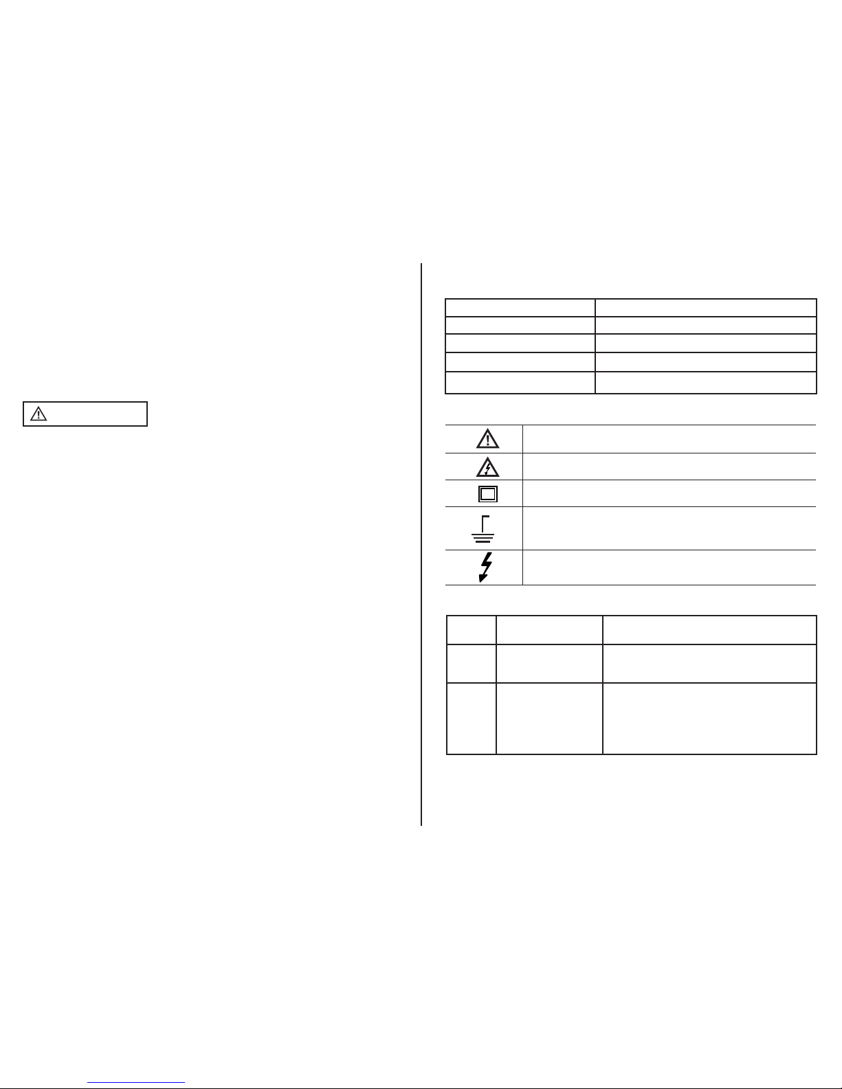
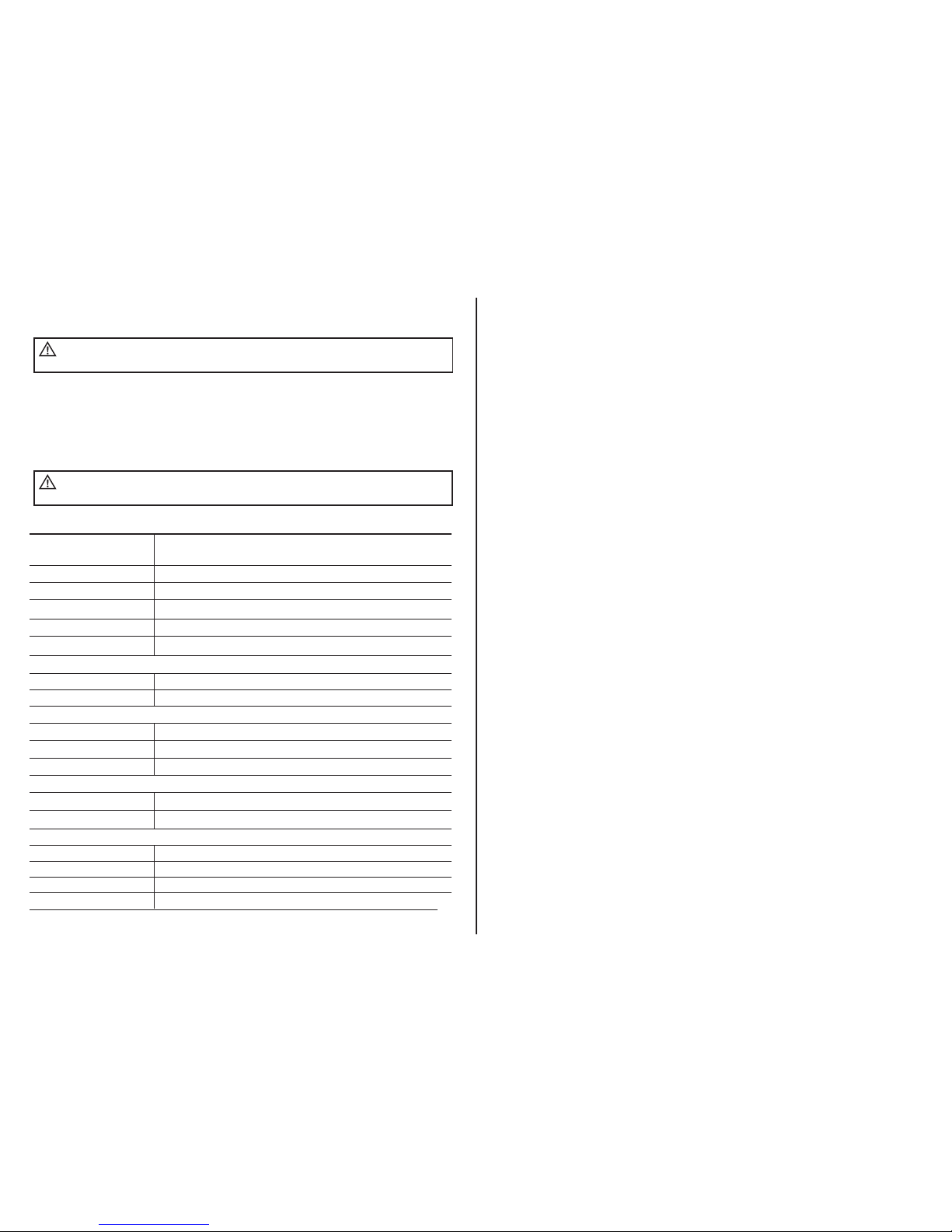
Especificaciones
LED de rango de voltaje
Tolerancias
Tiempo de respuesta
Rango de frecuencia ACV
Tiempo de operación
Tiempo de recuperación
6, 12, 24, 36, 48, 110, 220, 400V DC
24, 48, 120, 208, 240, 277, 480, 600V AC
-30% a 0% de la lectura
< 0.1s LED
50/60Hz
30 segundos máx.
10 minutos después de alcanzar el tiempo de operación máximo
100 a 480V AC
50/60Hz
<300kΩ
5µA
600VAC/DC
100 a 400V AC
50/60Hz
2x1.5V Baterías “AAA”
14°F a 131°F (-10°C hasta 55°C)
max. 80% humedad relativa
CATIII - 600V
Rango de voltaje
Rango de frecuencia ACV
Prueba de voltaje unipolar
Rango de Resistencia
Prueba de corriente
Protección de sobre voltaje
Prueba de Continuidad
Fuente de energía
Rango de temperatura
Humedad
Clase de sobre voltaje
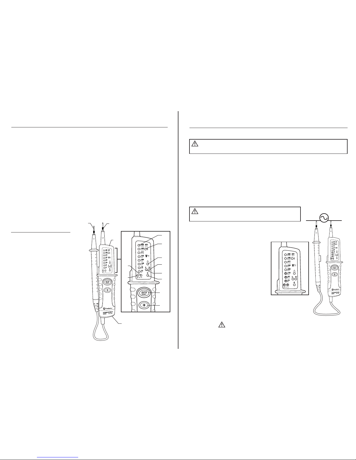
Información General
LEDs de rango de voltaje
Rango de frecuencia
Indicación de campo giratorio
1. Retire el tornillo Phillips ubicado en la parte inferior del comprobador.
2. Retire la tapa de la batería.
3. Cambie las dos baterías AAA de 1.5V.
4. Mantenga la polaridad correcta.
5. Instale la tapa de la batería y apriete el tornillo.
6. Presione el botón de “AUTO TEST” para confirmar la operación.
Para evitar la electrocución, desconecte las sondas
de cualquier fuente de voltaje antes de retirar la cubierta de la batería.
ADVERTENCIA:
Para evitar la electrocución, no utilice su
comprobador hasta que la cubierta de la batería esté bien asegurada.
ADVERTENCIA:
8
REGISTRE SU PRODUCTO
Registre su producto en www.southwiretools.com o al escanear el código QR en
este manual. En Southwire, estamos dedicados a proveer la mejor experiencia al
cliente. Al seguir unos pasos rápidos para registrar su producto, usted puede recibir
un servicio más rápido, ayuda más efectiva, e información acerca de futuros
productos. Simplemente proporcione el número de modelo y serie de su producto,
y alguna información personal – es así de fácil y rápido.
GARANTÍA LIMITADA Y LIMITACIÓN DE RESPONSABILIDAD EN MEDIDORES Y
PROBADORES DE SOUTHWIRE
Southwire Company, LLC garantiza este producto contra defectos en materiales y
mano de obra por dos años desde de la fecha de compra. Esta garantía no cubre
fusibles, baterías desechables, ni daños como resultado de un accidente, negligencia,
mala aplicación, contaminación, modificación, mantenimiento o reparación indebida,
uso fuera de las especificaciones, o manipulación anormal del producto. La única
responsabilidad de Southwire, y el único remedio del comprador, por cualquier
incumplimiento de esta garantía está limitada expresamente a la reparación o
reemplazo del producto por parte de Southwire. La reparación o reemplazo del
producto se hará bajo la determinación de Southwire y a su discreción.
SOUTHWIRE NO GARANTIZA QUE ESTE PRODUCTO SERÁ COMERCIABLE O ADECUADO PARA ALGÚN
PROPÓSITO EN PARTICULAR. SOUTHWIRE NO HACE NINGUNA OTRA GARANTÍA, EXPRESA O IMPLÍCITA,
SALVO QUE LA GARANTÍA ESPECÍFICAMENTE MENCIONADA EN ESTE PÁRRAFO. SOUTHWIRE NO SERÁ
RESPONSABLE DE DAÑOS INCIDENTALES, CONSECUENCIALES, INDIRECTOS, ESPECIALES, O PUNITIVOS
POR CUALQUIER INCUMPLIMIENTO DE ESTA GARANTÍA. Esta garantía no será válida si el
producto se utiliza para propósitos de alquiler. Ningún vendedor de productos está
autorizado para extender la garantía a nombre de Southwire en relación a este
producto, y la garantía de ningún vendedor será vinculante para Southwire. Si necesita
reclamar una garantía, o si el producto necesita servicio durante o después del periodo
de garantía mencionado en este documento, por favor contacte a Servicio al Cliente al
855-SWTOOLS (855-798-6657) o visite www.southwiretools.com para obtener una
autorización para devolver (RA) el producto, en la página web, haga clic en “Service
Department” para pedir un número de RA).
Usted debe obtener un número RA de Southwire antes que Southwire pueda procesar
la reclamación de garantía o pueda hacer cualquier servicio. La persona que haga la
devolución será responsable de los costos de envío y seguro asociados con enviar un
producto a Southwire. Southwire no se responsabiliza por productos dañados o
perdidos durante la devolución relacionada a esta garantía.
Todos los productos que se devuelvan a Southwire bajo esta garantía se deben
enviar a:
Southwire Company, LLC
Attention: Tool Warranty Return
840 Old Bremen Road
Carrollton, GA 30117
Table of contents
Languages:
Other Southwire Measuring Instrument manuals

Southwire
Southwire 41161N User manual

Southwire
Southwire 22070T User manual

Southwire
Southwire 14090T User manual

Southwire
Southwire SURGE GUARD 67030 Manual

Southwire
Southwire MaintenancePRO 23030T User manual

Southwire
Southwire 14060S User manual

Southwire
Southwire 21010N User manual

Southwire
Southwire 23090T MaintenancePRO User manual

Southwire
Southwire 40110N User manual

Southwire
Southwire 21005N User manual