manuals.online logo
Brands
  1. Home
  2. •
  3. Brands
  4. •
  5. Southwire
  6. •
  7. Measuring Instrument
  8. •
  9. Southwire SURGE GUARD 67030 Manual

Southwire SURGE GUARD 67030 Manual

For technical assistance, please call 1-800-780-4324 x 20311
Manufactured by Southwire Company, LLC, 4525 140th Avenue North, Suite 900, Clearwater, Florida 33762
© 2017 Southwire Company, LLC. All rights reserved. * Trademark of Southwire Company, LLC. Registered in the United States.
MODEL 67030
PORTABLE
MODEL 67050
PORTABLE
INPUT POWER CORDS
OVER/UNDER VOLTAGE PROTECTION
Should voltage drop below 102V or rise above 132V for more than 8
seconds, power to watercraft is turned off.
SEE TIME DELAY INDICATOR
The green LED indicates power to Watercraft
when illuminated.
TIME DELAY INDICATOR
When unit is plugged in, the red caution LED is
ashing indicating delay. The LCD at the same
will count up to 128 seconds. When the delay
expires, the red caution LED will stop ashing
and power will be applied to the watercraft.
Time delay will also be applied to reset once
power is restored to a safe range following
the 128 second delay. This allows head
pressure to bleed off the A/C Compressor.
SURGE FAILURE
If the red “SURGE” indicator LED is on,
it means that the built-in surge protection
has been sacriced to protect your
equipment and is no longer functioning
properly. Other features will still function,
but the unit is recommended to be replaced.
OUTPUT POWER CORDS
CAUTION LIGHT POLARITY
PROTECTION
Indicates possible miswiring or current to
ground condition present. (Will prevent
power on 50 amp unit only.) The LCD screen
will also indicate REVERSE POLARITY.
3 MODE SURGE PROTECTION
Protects the watercraft's sensitive electronic
systems and appliances from potentially
damaging power surge events without
power interruptions to the watercraft.
www.rvpower.southwire.com
FOR YOUR RECORDS
MODEL NO: ___________________
DATE PURCHASED: ____________
WHERE PURCHASED: __________
INSTALLATION & OPERATING
INSTRUCTIONS
505-00063C
Display During Fault Conditions
When the device is powered up, the LCD screen will display "Delay" and
the elapsed time in seconds until it reaches 128 seconds. After the delay
is completed, the unit will go to the normal operating screen showing
voltages and currents as described above. If there is a fault condition
during normal operation such as high or low voltage, the unit will display
that L1 or L2 is high or low; and when power comes back within range
(102V-132V) the unit will begin the delay as described above before
returning to the main screen that shows the voltages and currents.
Reverse Polarity Conditions
If the polarity of the voltages coming into the watercraft is reversed, then
the Surge Guard unit will display the REVERSE POLARITY until this
condition is corrected. Also, current or voltages on ground will
REVERSE POLARITY be displayed as reversed polarity.
TECHNICAL SPECIFICATIONS
1. Plug the Surge Guard* model 67030/67050 into an approved
watercraft receptacle and plug the watercraft power cord into the
Surge Guard unit.
2. Verify the delay indicator is ashing, the LCD is counting. The LCD
will read between 102V and 132V.
3. Once caution light stops ashing (this takes 128 seconds), verify
watercraft power is on.
NOTE: USING WITH POWER CORD ADAPTERS
Purchased power cord adapters will work in most cases with Surge
Guard units but Southwire does not recommend using them for full load
applications due to the possibility of over-heating. Be advised that power
cord adapters have been known to cause res when Amps (electrical
current) ratings are exceeded. Should you decide to use an adapter, our
recommendation is to check on the power cord from time to time to make
sure it is not overheating.
OPERATING INSTRUCTIONS
MODELS 67030 67050
TROUBLESHOOTING
Display for Normal Operation
During normal operation, the device's LCD screen alternates between
two displays, a main screen showing voltages and currents for power
lines 1 and 2 coming into the watercraft; and a secondary screen
showing whether power to the watercraft is ON or OFF, with voltage for
line 1 coming into the watercraft.
The main screen for model 67050 (50Amp) will show the voltages and
currents for lines 1 and 2, whereas model 67030 will only show line 1
since there is no line 2 for that model.
There are two rows or text lines on the LCD screen. The top row for
the main screen shows information for line 1 in the following format:
120V 50A. This means that the voltage on power line 1 coming into
the watercraft is at 120 volts and the watercraft is drawing 50 amps of
current on line 1. The bottom row of the main screen for 67050 shows
voltage and current for line 2.
FEATURES MODEL 67030 MODEL 67050
Operating Current 30 Amps 50 Amps
Operating Voltage 120 Volts 120/240 Volts
Maximum Watts 3600 Watts 12000 Watts
3 Mode Surge Protection Yes, L-N, L-G, N-G Yes, L-N, L-N, L-G,
N-G, L-L
Energy Dissipation 2450 Joules 3850 Joules
Clamping Voltage < 300 VAC < 300 VAC
Maximum Spike Current 6500A per MOV 6500A per MOV
Over/Under Voltage Protection Yes Yes
Voltage Range 132/102V 132/102V
Trip Time 8-10 seconds 8-10 seconds
High Neutral Current Trip N/A 130%
Time Delay for A/C 128 seconds 128 seconds
Reverse Polarity Check Yes 128 seconds
Voltage On Ground Check Yes Yes
Power Indicator LCD Voltage &
current reading
LCD Voltage &
current reading
Warranty 1 year 1 year
Corrosion Resistant Yes Yes
Easy Installation Yes Yes
Industrial Contactor Yes Yes
SYMPTOM CAUSE SOLUTION
Caution light is
ashing
There is a fault.
Read LCD for infor-
mation.
For reverse
polarity or voltage
on ground, move
watercraft to new
electrical source.
LCD reads less than
102V on rst line or
L1, L2 low on either
line.
1. Only partial
power at 50
Amp source.
2. No power at
source
1. Move to a new
source
2. Use inverter
or generator
power
When rst plugging
into pedestal power,
caution light ashes
momentarily, then
goes out.
High or low voltage
is present at source.
Change site or use
inverter or generator
power
LCD DISPLAY INDICATORS
REPLACE
SURGE
Surge expended
OPEN
GROUND
Open ground
REVERSE
POLARITY
Any line wired to neutral
L1 High
118V 42A 115V 32A
L2 High
Voltage > 132
L1 High
L2 Low
L1 Low
118V 42A
Voltage < 102
NEUTRIP
CUR=65A
Current > 130%
CUR
HIGH
Current > 125%
The top row of the secondary screen for both models shows ON or OFF,
and the bottom row shows the voltage on power Line 1 as L1=120V.
If the power coming into the watercraft is less than 102 volts on either
line 1 or 2, then the main screen will show L1 Low or L2 Low, in place of
the voltage or current. If the power coming in is greater than 132 volts,
then the main screen will show L1 high or L2 high.
Delay
011 Sec
REVERSE
POLARITY
120V 30A
RV STATUS ON/OFF
L1 120V
RV STATUS ON/OF
L1 120V
F
Model 67050 Model 67030
Main Screen
Secondary Screen
120V 25A
120V 25A
505-00063C
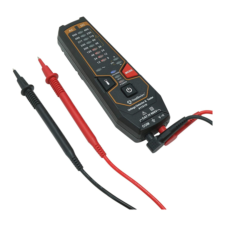
Other Southwire Measuring Instrument manuals

Southwire M555TP User manual

Southwire

Southwire M555TP User manual

Southwire 40110N User manual

Southwire

Southwire 40110N User manual

Southwire 14090T User manual

Southwire

Southwire 14090T User manual

Southwire 21010N User manual

Southwire

Southwire 21010N User manual

Southwire M300P User manual

Southwire

Southwire M300P User manual

Southwire 14060S User manual

Southwire

Southwire 14060S User manual

Southwire 60040S User manual

Southwire

Southwire 60040S User manual

Southwire 23090T MaintenancePRO User manual

Southwire

Southwire 23090T MaintenancePRO User manual

Southwire 40120N User manual

Southwire

Southwire 40120N User manual

Southwire 41161N User manual

Southwire

Southwire 41161N User manual

Southwire MaintenancePRO 23070T User manual

Southwire

Southwire MaintenancePRO 23070T User manual

Southwire MaintenancePRO 23030T User manual

Southwire

Southwire MaintenancePRO 23030T User manual

Southwire 41170S User manual

Southwire

Southwire 41170S User manual

Southwire 40130N User manual

Southwire

Southwire 40130N User manual

Southwire 22070T User manual

Southwire

Southwire 22070T User manual

Southwire 16040T User manual

Southwire

Southwire 16040T User manual

Southwire 21005N User manual

Southwire

Southwire 21005N User manual

Popular Measuring Instrument manuals by other brands

Parametric TCR user manual

Parametric

Parametric TCR user manual

Interacoustics AC40 Service manual

Interacoustics

Interacoustics AC40 Service manual

Gima Simpson 400 Operator's manual

Gima

Gima Simpson 400 Operator's manual

NDT Experts ExScan1000 manual

NDT Experts

NDT Experts ExScan1000 manual

Perel E305EM6 manual

Perel

Perel E305EM6 manual

OfiTE 130-85 instruction manual

OfiTE

OfiTE 130-85 instruction manual

GF JRG Coral force 8000 operating manual

GF

GF JRG Coral force 8000 operating manual

Troxler 4640-B Operation and instruction manual

Troxler

Troxler 4640-B Operation and instruction manual

Clas Ohlson ET-928 manual

Clas Ohlson

Clas Ohlson ET-928 manual

Observator Instruments Diff-Automatic user manual

Observator Instruments

Observator Instruments Diff-Automatic user manual

Cooper Atkins HACCP Manager ENTERPRISE 37200 manual

Cooper Atkins

Cooper Atkins HACCP Manager ENTERPRISE 37200 manual

Perel ECM1 manual

Perel

Perel ECM1 manual

Siemens VDO Pro Cockpit instructions

Siemens VDO

Siemens VDO Pro Cockpit instructions

MICRO-EPSILON eddyNCDT 3010 instruction manual

MICRO-EPSILON

MICRO-EPSILON eddyNCDT 3010 instruction manual

Siemens 546-00303A installation instructions

Siemens

Siemens 546-00303A installation instructions

Insportline Slam Me 1 kg user manual

Insportline

Insportline Slam Me 1 kg user manual

Sifam Tinsley N20ZPLUS user manual

Sifam Tinsley

Sifam Tinsley N20ZPLUS user manual

Quantum Design MPMS Service note

Quantum Design

Quantum Design MPMS Service note

manuals.online logo
manuals.online logoBrands
  • About & Mission
  • Contact us
  • Privacy Policy
  • Terms and Conditions

Copyright 2025 Manuals.Online. All Rights Reserved.